- Chapter 2 Primitive Man In The Indian Subcontinent MCQs
- Chapter 3 Ancient History Of The Indian Subcontinent MCQs
- Chapter 5 Indian Sub Continent In The 6th Century BC MCQs


Alternating Current Direct Current Or DC And Alternating Current Or Ac
Before discussing alternating current thoroughly, it would be helpful to recapitulate on direct current in short.
Direct Current (dc): In an electrochemical cell, the electrical nature of the positive and negative electrodes remains unchanged, i.e., it does not vary with time. The current in a circuit from this cell always remains unidirectional.
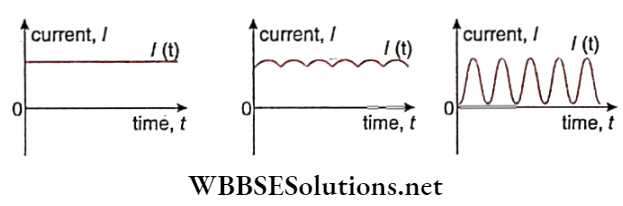
Alternating Current (ac): An electrochemical cell does not provide large amounts of electrical energy. All electric power plants use a machine called a dynamo or generator for this purpose.
Read and Learn More Class 12 Physics Notes
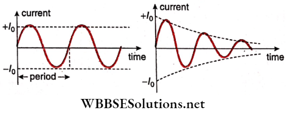
The following characteristics of alternating current are to be noted.
Almost the entire electrical energy requirement of the present-day world is derived from the phenomenon of electromagnetic induction.
The machine employing this phenomenon is called a dynamo or generator. A conducting coil is set to rotate inside a magnetic field, as a result of which a current is induced in the coil. This is the basic mechanism.
Definition: The machine in which the mechanical energy of a rotating conducting coil placed in a magnetic field is converted into electrical energy, is called a dynamo or generator.
Description: The main parts of an alternating current dynamo are shown.
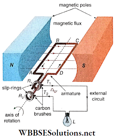
N, S: The poles of a strong horseshoe magnet which produces a uniform magnetic field directed from the north to the south pole in the gap between them. Some lines of force are shown in the figure. This magnet is called the field magnet.
ABCD: A rectangular coil called an armature is placed in a uniform magnetic field, which usually contains several turns.
The coil in this case is made to rotate about the axis normal to the magnetic field; the direction of rotation in this case is as shown in the diagram.
R1, R2: Two smooth brass rings called slip rings. They are connected to the coil at its open ends A and D.
T1, T2: Two carbon brushes fitted to the rings with the help of springs, which keep the brushes pressed against the rings R1 and R2.
L: An electric lamp, to indicate the presence of current.
Observation: The lamp glows as long as the coil rotates. From this, we can infer that an electric current is flowing through the external circuit attached to T1 and T2. As soon as the rotation of the coil ceases, the current stops and the lamp goes out.
WBBSE Class 12 Alternating Current Notes
Working Principle: when the coil ABCD arms AB and CD intersect the magnetic lines of force. As a result, electromagnetic induction takes place.
As a result, current flows in the second half of rotation from T2 to T1 in the external circuit. Thus, the polarities of T1 and T2 get reversed, reversing the direction of the current.
Factors Affecting The Emf And Current: The electromotive force, and hence the current is directly proportional to
So, if any one of them is increased, the emf will also increase. The current however will decrease with an increase in the resistance of the circuit.
Electric motor: The principle of action of an electric motor is just opposite to that of a dynamo.
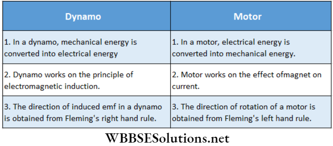
Differences Between Dynamo And Motor:
However, the discussions on both DC and AC motors are beyond our present syllabus.
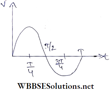
Waveform Of Alternating Current: Let a rectangular. coil ABCD is rotating with uniform angular velocity in a uniform magnetic field. The coil is viewed in a way such that only the AD end of the coil becomes visible. The different positions of this end concerning time are shown.
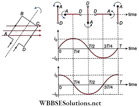
Let the period of the coil be T. If the coil starts rotating from its vertical position, then at \(\frac{T}{2}\) and T, it again comes to its vertical position.
At these moments both AB and CD are moving parallel to the magnetic field. Considering the equation, e = Blvsind with θ = 0° the induced emf and hence the induced current will be zero.
On the other hand, at the times \(\frac{T}{4}\) and \(\frac{3T}{4}\), the coil lies horizontally. At those positions,r. AB and CD are directed normally to the magnetic field (θ = 90°), and the induced current becomes maximum.
However, at the time \(\frac{T}{4}\), the direction of current is along DCBA, while at the time \(\frac{3T}{4}\), it is along ABCD. So, if the current in the first case is taken as positive, then the current in the second case will be negative.
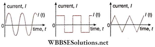
This figure clearly shows a sine-wave; this is the wave nature of current if the coil starts rotating from its vertical position.
On the other hand, if the coil, starts rotating from its horizontal position, the current Will be a cosine-wave. Note that, both sine and cosine waves are called sinusoidal waves.
The current completes a cycle of change in a time equal to the period of rotation of the coil. A complete wave is thus formed in every cycle.
Expression Of Alternating Current: Let a rectangular coil be rotating with uniform angular velocity ω in a uniform. magnetic field B. At any moment t, the angle between the normal to the coil and the direction of the magnetic field is θ, say.
If the area of the plane of the coil is A, the magnetic flux linked with the coil,
Φ = BAcosθ → (1)
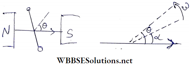
Initially, the angle between the normal to the plane of the coil and the direction of the magnetic field = α (say). After rotation for time t, this angle becomes,
θ = ωt + α
So, from equation (1) we get, magnetic flux,
Φ= BA cos (ωt+α) → (2)
Hence, the magnitude of the induced emf in the coil of a single turn
⇒ \(e=\frac{d \phi}{d t}=\omega B A \sin (\omega t+\alpha)\)
For N turns,
⇒ \(e=\omega B A N \sin (\omega t+\alpha)=e_0 \sin (\omega t+\alpha)\) → (3)
[here, e0 = ωBAN]
If the total resistance of the coil and the external circuit is R, the induced current,
⇒ \(i=\frac{e}{R}=\frac{\omega B A N}{R} \sin (\omega t+\alpha)=\frac{e_0}{R} \sin (\omega t+\alpha)\)
⇒ i0sin(ωt + α) → (4)
Phase: The state of alternating current at any moment is expressed by its phase. In equations (3) and (4), (ωt + α) is the phase of the alternating current.
Phase Difference: If the phases of two alternating currents are δ1 and δ2, then(δ1-δ2) is the phase difference of those two currents.
If co is the same for the two currents, the phase difference
becomes (α1– α2)
Peak Value: As -1 ≤ sinθ ≤ 1, it can be concluded that
These magnitudes, e0 and i0 are called the peak values of electromotive force and current.
Dependence Of Peak Value On Different Factors: it is obvious from equations (3) and (4) that the peak values of emf as well as current depend directly on each of the quantities involved, viz., co, B, A, N. Moreover, the peak value of current also varies inversely with the resistance (R) of the circuit.
Period And Frequency: The definite time interval in which a complete cycle repeats itself, is called the period (T) of an alternating current.
If the angular velocity, of the coil, is co, then
∴ \(T=\frac{2 \pi}{\omega}\) → (5)
The number of complete waves produced in unit time is called the frequency (n) of an alternating current.
So, \(n=\frac{1}{T}=\frac{\omega}{2 \pi}\) → (6)
Frequency is the most important quantity in the expression of an ac. It is noted that the frequency of domestic electric supply in India is 50 Hz or 50 cycles per second(cps). It indicates that the direction of the current is reversed (50 x 2) or 100 times per second.
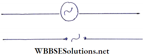
It represents the symbols of an AC source used in a circuit. Any of these symbols may be used for the purpose.
Average Values Of Alternating Voltage And Current
Alternating voltage (V) or Current (I) always increases, decreases, and changes periodically following the functions since or cos ωt. But the average values of these quantities, do riot change with time.
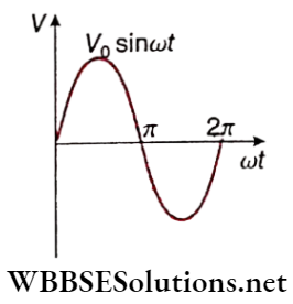
Calculation: Let an expression for sinusoidal alternating voltage,
V = V0 Sin ωt
Average value of it in a full cycle (i.e., for t = T)
= \(\frac{1}{T} \int_0^T V d t=\frac{1}{T} \int_0^T V_0 \sin \omega t d t=0\)
This is because the voltage in a half cycle is positive and in the next half it is of the same magnitude, but negative.
Short Notes on AC Circuits
For convenience, the average value in a half-cycle, instead of in a full-cycle, in ac is considered as the average value \((\bar{V})\) of an alternating voltage.
∴ \(\bar{V}=\frac{1}{T / 2} \int_0^{T / 2} V_0 \sin \omega t d t=\frac{2 V_0}{\omega T}[-\cos \omega t]_0^{T / 2}\)
= \(\frac{2 V_0}{\pi}=0.637 V_0\)
Similarly, the average value of alternating current,
∴ \(\bar{I}=\frac{2 I_0}{\pi}=0.637 I_0\)
Class 12 Physics Alternating Current notes RMS Values Of Alternating Voltage And Current
Alternating voltage or current cannot be measured directly with instruments like galvanometers. They can only be measured indirectly following the thermal effect of current.
We know that heat generated in a current-carrying conductor is directly proportional to V2 or l2, i.e., heat thus generated does not depend on the direction of the current.
The effective value, being the root of the average (or mean) of the square of the currents, is known as the root mean square (in short, rms) value.
Calculation: Let an expression for sinusoidal alternating voltage,
v = v0 sinωt
So, the mean square of V,
∴ \(\vec{V}^2=\frac{1}{T} \int_0^T V^2 d t=\frac{1}{T} \int_0^T \cdot V_0^2 \sin ^2 \omega t d t\)
= \(\frac{V_0^2}{2 T} \int_0^T(1-\cos 2 \omega t) d t=\frac{V_0^2}{2 T}\left[t-\frac{\sin 2 \omega t}{2 \dot{\omega}}\right]_0^T\)
= \(\frac{V_0^2}{2 T}\left(T-\frac{\sin 4 \pi}{2 \omega}+\frac{\sin 0}{2 \omega}\right)\) [∵ ωt = 2π]
= \(\frac{v_0^2}{2}\)
∴ rms value of V,
⇒ \(V_{\mathrm{rms}}=\sqrt{\bar{V}^2}=\sqrt{\frac{V_0^2}{2}}=\frac{V_0}{\sqrt{2}}=0.707 V_0\)
Similarly, rms value of I,
⇒ \(I_{\mathrm{rms}}=\frac{I_0}{\sqrt{2}}=0.707 I_0\)
i.e., rms voltage = 70.7% of peak voltage
and rms current = 70.7% of peak current
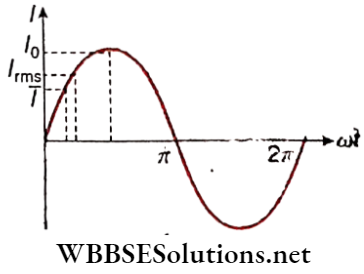
Relation between peak value, average value, and rms value of alternating voltage and current: From the above discussion we have,
⇒ \(\bar{V}=\frac{2 V_0}{\pi}=0.637 V_0\)
and \(V_{\mathrm{rms}}=\frac{V_0}{\sqrt{2}}=0.707 V_0\)
where V0 is the peak value of alternating voltage.
∴ \(V_{\mathrm{rms}}: \bar{V}=\frac{V_0}{\sqrt{2}}: \frac{2 V_0}{\pi}=\frac{\pi}{2 \sqrt{2}}\)
or, \(V_{\mathrm{rms}}=\frac{\pi}{2 \sqrt{2}} \bar{V}=1.11 \bar{V}\)
∴ \(V_{\text {rms }}>\bar{V}\)
Similarly, \(I_{\mathrm{rms}}>\bar{I}\)
This relation is shown graphically.
We know that the heating effect of electric current is directly proportional to I2. Hence ac ammeters and ac voltmeters, are designed based on the heating effect of current. They directly measure rms values of alternating current and voltage respectively.
Form Factor: The ratio of the rms value and the average value of alternating voltage or current is known as the form factor.
Thus form factor, \(f=\frac{V_{\mathrm{rms}}}{\bar{V}}=\frac{\frac{V_0}{\sqrt{2}}}{\frac{2 V_0}{\pi}}=\frac{\pi}{2 \sqrt{2}}=1.11\).
Note that, the above value of form factor applies only to sinusoidal voltage arid current. For different waveforms, the values of the form factor are different. For example, for a square wave
∴ \(V_{\mathrm{rms}}=V_0 \text { and } \bar{V}=V_0\)
∴ Form factor, \(f=\frac{V_{\mathrm{rms}}}{\bar{V}}=1\)
From the form factor of an alternating voltage or current an effective idea about the waveform can be obtained.
Effects Of Oil An Ac Or DC Currents On The Human Body: the three main factors that determine what kind of shock one experiences are the amplitude, frequency, and duration of the current passing through the body.
Direct current has zero frequency i.e., it has a constant amplitude. On the other hand, the peak value of an ac voltage (V0) is √2. times its rms value (Vrms), for example., a 220V ac supply is going 220√2 or 311 V (approx.) before coming down to zero.
So, one can get a 311V shock from a 220V-50Hz ac supply line for (50 x 2) hor 100 times per second. The calculation indicates the severity of electrocution from ac compared to that from the decision of average for the same duration of time.
Class 12 Physics Alternating Current notes
Example 1. Equation of an ac is \(I=, 10 \sin \left(200 \pi t-\frac{\pi}{15}\right)\) ampere. Determine the frequency and peak value of the current.
Solution:
Comparing with the general equation of ac, I = I0 sin(ωt + α) we get,
the peak value of current, I0 = 10 A
and angular frequency, ω = 200 π Hz
∴ Frequency, \(I=\frac{\omega}{2 \pi}=\frac{200 \pi}{2 \pi}=100 \mathrm{~Hz}\)
Example 2. If an ac is represented by I = 100 sin 200 πt ampere, determine the peak value of the current and period.
Solution:
Comparing with the general equation of ac, I = I0 sin(ωt+α) we get,
the peak value of current, I0 = 100 A
and angular frequency, ω = 200π HZ
∴ Time period, T = \(T=\frac{2 \pi}{\omega}=\frac{2 \pi}{200 \pi}=0.01 \mathrm{~s}\)
Example 3. An alternating current having a peak value of 141 A Is used to heat a metal wire. To produce the same rate of heating effect, another constant current IA is used. What is the value of I?
Solution:
∴ \(I_{\mathrm{rms}}=\frac{I_0}{\sqrt{2}}=\frac{141 \mathrm{~A}}{\sqrt{2}}=100 \mathrm{~A}\)
If a steady DC I produces the same rate of heating, then I = Irms = 100A.
Example 4. The peak value of an alternating magnetic field B is 0.01 T and the frequency is 100 Hz. If a conducting ring of radius 1 m is held normal to the field, what emf will be induced in the ring?
Solution:
n = 100 Hz
∴ Time period, \(T=\frac{1}{n}=\frac{1}{100} \mathrm{~s}\)
The time taken by the field to increase from 0T to, 0.01 T is \(\frac{T}{4}=\frac{1}{400} \mathrm{~s}\).
Now the area, A = π. m2 = π m2
Hence induced emf,
∴ \(|e|=\frac{d \phi}{d t}=\frac{d}{d t}(B A)=A \frac{d B}{d t}\)
or, \(|e|=\pi\left(\frac{0.01-0}{\frac{1}{400}}\right)=4 \pi \mathrm{V}=12.57 \mathrm{~V}\)
Power consumed In ac circuits: In any dc circuit, the potential difference (voltage) and the current are always in phase. But this is not so for ac circuits—in general, a phase difference is evolved between the voltage and the current Mathematically the voltage V and the current I are expressed as,
V = V0 sinωt and I = I0 sin(ωt-θ)
where, θ = phase difference between the voltage and the current. θ always lies between -90° and +90°, i.e., -90° ≤ θ ≤ 90°. Then, power consumed (or power dissipated) in the circuit is,
∴ \(P=V I=V_0 I_0 \sin \omega t \sin (\omega t-\theta)\)
= \(V_0 I_0 \sin \omega t[\sin \omega t \cos \theta-\cos \omega t \sin \theta]\)
=\(V_0 I_0\left[\sin ^2 \omega t \cos \theta-\sin \omega t \cos \omega t \sin \theta\right]\)
= \(V_0 I_0\left[\sin ^2 \omega t \cos \theta-\frac{1}{2} \sin 2 \omega t \sin \theta\right]\)
Over a complete cycle, the average of \(\sin ^2 \omega t=\frac{1}{2}\) and that of sin2ωt = 0. So the average power of the circuit is,
∴ \(\bar{P}=\frac{1}{2} V_0 I_0 \cos \theta=\frac{V_0}{\sqrt{2}} \frac{I_0}{\sqrt{2}} \cos \theta=V_{\mathrm{rms}} I_{\mathrm{rms}} \cos \theta\)
No experiment can measure the instantaneous power P; every measurement leads to the average power \(\bar{P}\). This \(\bar{P}\) is referred to as the effective power, and is usually denoted by the simple symbol P. So the effective power (or true power) of an ac circuit is,
∴ \(P=\frac{1}{2} V_0 I_0 \cos \theta=V_{\mathrm{rms}} I_{\mathrm{rms}} \cos \theta\) → (1)
Common Questions on Alternating Current
Power Factor: The factor cosθ in equation (1) is vitally important; this factor arises, clearly, due to the voltage-current phase difference θ. This cosθ is called the power factor of an ac circuit.
true power = apparent power x power factor.
If voltage and current are in the same phase, then θ = 0 and cos θ = 1. In this condition, an ac circuit consumes the maximum power.
If the voltage and the current are either -90° or +90° out of phase, then cos θ = 0 and P = 0. An ac circuit of this type consumes no power. The corresponding current is referred to as wattless current.
Time Interval Between The Peak Values Of Voltage And Current:
v = v0 sinωt, I = I0sin(ωt-θ)
So, \(V=V_0, \text { when } \omega t=\frac{\pi}{2}, \text { i.e., } t=\frac{\pi}{2 \omega}\)
Similarly, \(I=I_0 \text {, when }\left(\omega t^{\prime}-\theta\right)=\frac{\pi}{2} \text {, i.e., } t^{\prime}=\frac{\pi}{2 \omega} 4 \frac{\theta}{\omega}\)
Thus, the minimum time interval between the peak values of ac voltage and current is,
∴ \(t_0=t^{\prime}-t=\frac{\theta}{\omega}\)
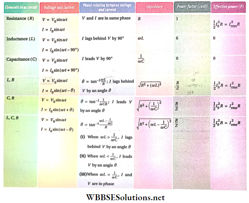
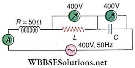
WBCHSE Physics Alternating Current study material Purely Resistive Circuit
shows the circuit. Alternating voltage applied in the circuit,
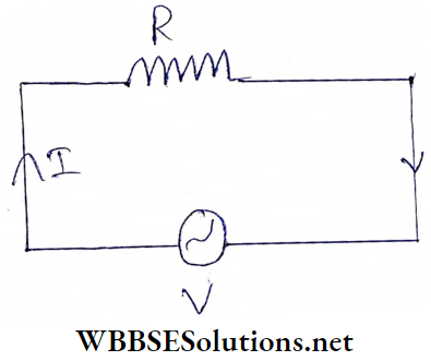
V = V0sinω t → (1)
Here, the peak value of alternating voltage = v0
rms value, vrms = \(\frac{V_0}{\sqrt{2}} ; \text { frequency, } f=\frac{\omega}{2 \pi}\).
According to Ohm’s law,
⇒ \(I=\frac{V}{R}=\frac{V_0}{R} \sin \omega t\)
Or, \(I=I_0 \sin \omega t\)
So, the peak value of ac, \(I_0=\frac{V_0}{R}\)
⇒ rms value, \(I_{\mathrm{rms}}=\frac{I_0}{\sqrt{2}}=\frac{V_0}{\sqrt{2} R}=\frac{V_{\mathrm{rms}}}{R}\);
⇒ frequency, \(f=\frac{\omega}{2 \pi}\)
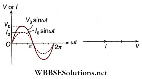
The factor sinωt in equations (1) and (2) indicates that
Practice Problems on Alternating Current
Power in the circuit: Phase difference between voltage and current, θ = 0; so, power factor, cosθ = 1. For this, maximum power is consumed in a purely resistive circuit, which is
∴ \(P=\frac{1}{2} V_0 I_0 \cos \theta=\frac{1}{2}\left(I_0 R\right) I_0 \cdot 1=\frac{1}{2} I_0^2 R=\left(\frac{I_0}{\sqrt{2}}\right)^2 R\)
i.e., P = Irms2.R → (3)
Purely Inductive Circuit
shows this circuit. Let the alternating voltage applied in the circuit be,
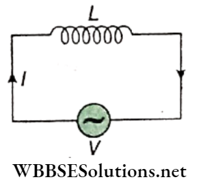
V = V0sin ωt → (1)
If the instantaneous change of current in the circuit is dl, the emf induced in the two ends of the inductor = \(-L \frac{d I}{d t}\)
This emf reduces the main voltage in the circuit. For this the effective voltage of the circuit = \(V_0 \sin \omega t-L \frac{d I}{d t}\).
A purely inductive circuit has no resistance i.e., R = 0. So according to Ohm’s law,
⇒ \(V_0 \sin \omega t-L \frac{d I}{d t}=0 \quad \text { or, } \frac{d I}{d t}=\frac{V_0}{L} \sin \omega t\)
or, \(\int d I=\int \frac{V_0}{L} \sin \omega t d t\)
or, \(I=-\frac{V_0}{\omega L} \cos \omega t+k\) [k = integration constant] → (2)
Dimensionally k is the same as I. Also, fc is a time-independent quantity. As the source voltage oscillates symmetrically about zero, the current also oscillates symmetrically about zero. For this, no constant or time-independent current can flow through the circuit, i.e., k = 0.
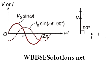
∴ \(I=-\frac{V_0}{\omega L} \cos \omega t=+\frac{V_0}{\omega L} \sin \left(\omega t-90^{\circ}\right)\)
or, I = I0sin(ωt-90°) →(3)
where \(I_0=\frac{V_0}{\omega L}\) = peak value of current.
From the equations (1) and (3) we come to the conclusions
current lags behind the voltage by 90°.
The quantity coL plays the same role in an inductive circuit as the resistance R in a resistive circuit. This quantity (i.e., ωL) is known as the inductive reactance of an ac circuit. Inductive reactance is the opposition offered by an inductor to the flow of alternating current through it. It is denoted by the symbol XL.
Hence for the above circuit,
XL = ωL = inductive reactance
Similar to that of R its unit is also ohm (Ω).
Power In The Circuit: Phase difference between voltage and current, θ = 90°, so, power factor, cosθ = 0.
Therefore, power consumption, \(P=\frac{1}{2} V_0 I_0 \cos \theta=0\)
The current I in this circuit is wattless.
WBCHSE Physics Alternating Current study material Purely Capacitive Circuit
shows the circuit. Alternating voltage applied in the circuit,
V = V0sin ωt →(1)
At any moment, if Q is the charge stored in the capacitor C, then its terminal potential difference is \(\frac{Q}{C}\)
This potential difference opposes the applied instantaneous voltage in the circuit.
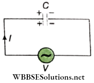
So, the effective voltage of the circuit, \(V_e=V_0 \sin \omega t-\frac{Q}{C}\)
As there is no resistance in the circuit, according to Ohm’s law, Ve = IR = 0
and hence, \(V_e=V_0 \sin \omega t-\frac{Q}{C}=0\)
or, Q = CV0sinωt → (2)
Therefore alternating current,
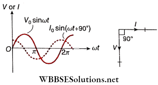
∴ \(I=\frac{d Q}{d t}=\omega C V_0 \cos \omega t=\omega C V_0 \sin \left(\omega t+90^{\circ}\right)\)
= I0sin(ωt+90°) → (3)
Where, \(I_0=\omega C V_0=\frac{V_0}{1 / \omega C}=\frac{V_0}{X_C}\) = peak value of current From the equations (1) and (3) we come to the conclusions
Current leads the applied voltage by 90°;
The quantity \(\frac{1}{\omega C}\)plays the same role in a capacitive circuit as the resistance R in a resistive circuit. This quantity (i.e., \(\frac{1}{\omega C}\) is known as capacitive reactance (XC).
Capacitive reactance is the opposition offered by a capacitor to the flow of alternating current through it. Hence for the above circuit.
∴ \(x_C=\frac{1}{\omega C}\) = capacity reactance
Similar to that of R or XL, its unit is also ohm (Ω).
Power In The Circuit: Phase’ difference between voltage and current, θ = -90°; so, power factor, cosθ = 0. Therefore, power consumption \(P=\frac{1}{2} V_0 I_0 \cos \theta=0\).
Here again, this current is wathers.
Wattless or Idle current: Power consumed in an ac circuit, \(P=\frac{1}{2} V_0 I_0 \cos \theta\). Now the phase difference between voltage and current in a pure inductive circuit, θ = 90°.
So power in the circuit is zero. On the other hand phase difference between voltage and current in a pure capacitive circuit, θ = -90°.
So, again power is equal to zero, which means, a purely inductive or capacitive circuit does not dissipate any power; current through the inductor or capacitor is hence called wattless or idle current.
LR Circuit
shows the circuit
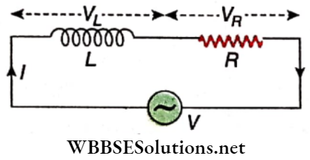
The applied alternating voltage,
V = V0sinωt → (1)
If the instantaneous change in current in of the circuit is dl, then the induced emf in the inductor \(L=-L \frac{d I}{d t}\);
i.e., the effective voltage in the circuit,
⇒ \(V_e=V_0 \sin \omega t-L \frac{d I}{d t}\)
According to Ohm’s law, Ve = IR, where the resistance, if any, of the inductor L is included in R.
∴ \(V_0 \sin \omega t-L \frac{d I}{d t}=I R\)
or, \(L \frac{d I}{d t}+R I=V_0 \sin \omega t\) → (2)
Let I = I0sin(ωt+ α)
or, \(\frac{d I}{d t}=\omega I_0 \cos (\omega t+\alpha)\)
So, putting the values of I and \(\frac{d I}{d t}\) in identity (2) we get
ωLI0 cos(ωt+α) + RI0 sin(ωt+α) = V0 sinωt
or, I0{R sin((ωt+ α) + L cos(ωt+α)} = V0 sinωt
or, \(I_0 \sqrt{R^2+(\omega L)^2}\{\frac{R}{\sqrt{R^2+(\omega L)^2}} \sin (\omega t+\alpha)+\frac{\omega L}{\sqrt{R^2+(\omega L)^2}} \cos (\omega t+\alpha)\}=V_0 \sin \omega t\)
or, \(I_0 Z\left\{\frac{R}{Z} \sin (\omega t+\alpha)+\frac{\omega L}{Z} \cos (\omega t+\alpha)\right\}=V_0 \sin \omega t \text { [where } Z=\sqrt{R^2+(\omega L)^2} \text { ] }\)
or, \(I_0 Z\{\sin (\omega t+\alpha) \cos \theta+\cos (\omega t+\alpha) \sin \theta\}=V_0 \sin \omega t \text { [where } \cos \theta=\frac{R}{Z} \text { and } \sin \theta=\frac{\omega L}{Z} \text { ] } \)
or, I0Zsin(ωt+ α + θ) = V0sin ωt
From this identity, comparing both sides we get,
⇒ \(I_0 Z=V_0 \quad \text { or, } I_0=\frac{V_0}{Z}=\frac{V_0}{\sqrt{R^2+(\omega L)^2}}\)
and α + θ = 0 or, α = -θ
So, the ac in the circuit,
∴ \(I=I_0 \sin (\omega t-\theta)=\frac{V_0}{Z} \sin (\omega t-\theta)\) → (3)
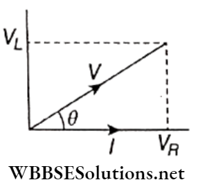
From equations (1) and (3) we conclude,
The current lags behind the applied voltage by a phase angle θ given by \(\tan \theta=\frac{\sin \theta}{\cos \theta}=\frac{\omega L}{Z} \times \frac{Z}{R}=\frac{\omega L}{R}\)
i.e., \(\theta=\tan ^{-1}\left(\frac{\omega L}{R}\right)\)
This phase relation is shown. We know that in a purely resistive circuit V and I are in the same phase i.e., phase difference, θ = 0. On the other hand, in a pure inductive circuit, I always lag behind V by θ = 90°. So in an LR circuit, I should lag behind V by 0 < θ < 90°.
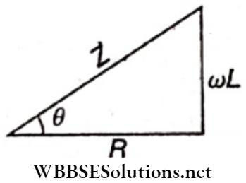
In this circuit, Z plays the same role as R in a pure resistive circuit. Z is known as the impedance of an ac circuit.
Impedance, \(Z=\sqrt{R^2+(\omega L)^2}=\sqrt{R^2+\left(X_L\right)^2}\) → (4)
where, XL = ωL = inductive reactance
Impedance in an LR circuit is the effective resistance of the circuit arising from the combined effects of ohmic resistance and inductive reactance.
We can express the relation among R, XL, and Z with a suitable right-angled triangle. This triangle is called the impedance triangle.
Note that, R, ωL, and Z have, the same unit ohm(Ω).
Power In The Circuit:
Here, the power factor of the circuit, \(\cos \theta=\frac{R}{Z}\)
∴ \(P=\frac{1}{2} V_0 I_o \cos \theta=\frac{1}{2}\left(I_0 Z\right) I_0 \cdot \frac{R}{Z}=\frac{1}{2} I_0^2 R=\left(\frac{I_0}{\sqrt{2}}\right)^2 R\)
i.e., \(P=I_{\mathrm{rms}}^2 R\)
This means that the power is dissipated only in the resistance R. Current through the inductor is wattless.
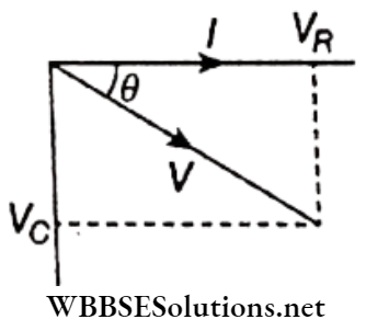
CR Circuit
It shows the circuit. Alternating voltage applied to the circuit,
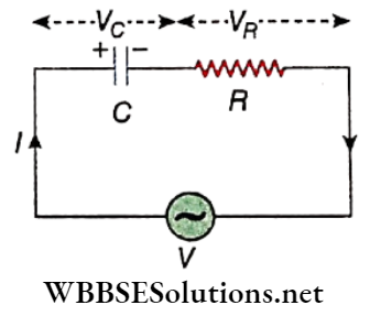
V = V0sin ωt → (1)
At any moment if Q is the charge stored in the capacitor C, then, the effective voltage in the circuit,
∴ \(V_e=V_0 \sin \omega t-\frac{Q}{C}\)
According to Ohm’s law
∴ \(V_0 \sin \omega t-\frac{Q}{C}=I R\)
or, \(R I+\frac{1}{C} Q=V_0 \sin \omega t\)
Now let us assume that Q = Q0 sin(ωt+ α)
∴ \(I=\frac{d Q}{d t}=\omega Q_0 \cos (\omega t+\alpha)\)
So, from the equation (2) we get,
∴ \(\omega R Q_0 \cos (\omega t+\alpha)+\frac{1}{C} Q_0 \sin (\omega t+\alpha)=V_0 \sin \omega t\)
or, \(\omega Q_0\left[R \cos (\omega t+\alpha)+\frac{1}{\omega C} \sin (\omega t+\alpha)\right]=V_0 \sin \omega t\)
or, \(\omega Q_0 Z\left[\frac{R}{Z} \cos (\omega t+\alpha)+\frac{1 /(\omega C)}{Z} \sin (\omega t+\alpha)\right]=V_0 \sin \omega t\)
[where \(Z=\sqrt{R^2+\left(\frac{1}{\omega C}\right)^2}\)(say)]
or, \(\omega Q_0 Z\{\cos (\omega t+\alpha) \cdot \cos \theta+\sin (\omega t+\alpha) \cdot \sin \theta\}=V_0 \sin \omega t\)
[where \(\frac{R}{Z}=\cos \theta \text { and } \frac{1 / \omega C}{Z}=\sin \theta\)(say)]
or, \(\omega Q_0 Z \cos (\omega t+\alpha-\theta)=V_0 \sin \omega t\)
or, \(\omega Q_0 Z \sin \left(\omega t+\alpha-\theta+90^{\circ}\right)=V_0 \sin \omega t\)
Comparing both sides we get,
∴ \(\omega Q_0 Z=V_0 \quad \text { or, } Q_0=\frac{V_0}{\omega Z}\)
and α – θ + 90° = 0 or, α = θ – 90°
So, alternating current in the circuit,
I = ωQ0cos(ωt+ α)
= \(\omega \frac{V_0}{\omega Z} \cos \left(\omega t+\theta-90^{\circ}\right)=\frac{V_0}{Z} \sin (\omega t+\theta)\)
i.e., \(I=I_0 \sin (\omega t+\theta)=\frac{V_0}{Z} \sin (\omega t+\theta)\) → (3)
Here, \(I_0=\frac{V_0}{Z}=\frac{V_0}{\sqrt{R^2+\left(\frac{1}{\omega C}\right)^2}}\)
From equations (1) and (3) we conclude the following.
1. The current I leads the voltage V by a phase angle θ, where \(\tan \theta=\frac{\sin \theta}{\cos \theta}=\frac{1 / \omega C}{Z} \times \frac{Z}{R}=\frac{1}{\omega C R}\),
i.e., \(\theta=\tan ^{-1}\left(\frac{1}{\omega C R}\right)\)
This phase relation is shown. We know that in a purely resistive circuit, V and I are in the same phase, i.e., phase difference, θ = 0. On the other hand, in a pure capacitive circuit, I always lead V by θ = 90°. So, in a CR circuit, I should lead V by 0 < θ < 90°.
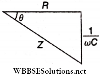
2. Z plays the same role as R in a pure resistive circuit. This Z is known as the impedance of the circuit.
Impendance, \(Z=\sqrt{R^2+\left(\frac{1}{\omega C}\right)^2}=\sqrt{R^2+X_C^2}\) → (4)
where \(X_C=\frac{1}{\omega C}\) = capacitive reactance.
Impedance in a CR circuit is the effective resistance of the circuit arising from the combined effects of ohmic resistance and capacitive reactance.
shows the impedance triangle for the circuit.
Power In The Circuit: Here, the power factor of the circuit, \(\cos \theta=\frac{R}{Z}\)
so, \(P=\frac{1}{2} V_0 I_0 \cos \theta=\frac{1}{2}\left(I_0 Z\right) I_0 \cdot \frac{R}{Z}=\frac{1}{2} I_0^2 R=\left(\frac{I_0}{\sqrt{2}}\right)^2 R\)
∴ P = I2rms.R2
Hence, power is dissipated only in the resistance R . Current through the capacitor C is wattless.
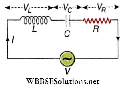
Series LCR Circuit
shows the circuit. Alternating voltage applied in the circuit,
V = V0sin ωt → (1)
If the instantaneous change in current in the circuit is dI, then the emf induced in the inductor
= \(-L \frac{d I}{d t}\).
On the other hand, if Q is the instantaneous charge stored in the capacitor, the opposite emf thus developed in the circuit = \(-\frac{Q}{C}\).
So, the effective voltage in the circuit,
∴ \(V_e=V_0 \sin \omega t-L \frac{d I}{d t}-\frac{Q}{C}\)
According to Ohm’s law,
∴ \(V_0 \sin \omega t-L \frac{d I}{d t}-\frac{Q}{C}=I R\)
or, \(L \frac{d I}{d t}+R I+\frac{Q}{C}=V_0 \sin \omega t\)
Now, let us assume, Q = Q0sin(ωt+ α)
So, current, \(I=\frac{d Q}{d t}=\omega Q_0 \cos (\omega t+\alpha)\)
or, \(\frac{d I}{d t}=-\omega^2 Q_0 \sin (\omega t+\alpha)\)
Putting these values in equation (2) we get,
= \(-\omega^2 L Q_0 \sin (\omega t+\alpha)+\omega R Q_0 \cos (\omega t+\alpha)+\frac{Q_0}{C} \sin (\omega t+\alpha)=V_0 \sin \omega t\)
or, \(\omega Q_0\left\{R \cos (\omega t+\alpha)-\left(\omega L-\frac{1}{\omega C}\right) \sin (\omega t+\alpha)\right\}=V_0 \sin \omega t\)
or, \(\omega Q_0 Z\left\{\frac{R}{Z} \cos (\omega t+\alpha)-\frac{\omega L-1 / \omega C}{Z} \sin (\omega t+\alpha)\right\}=V_0 \sin \omega t\)
[Where \(Z=\sqrt{R^2+\left(\omega L-\frac{1}{\omega C}\right)^2}\)]
or, \(\omega Q_0 Z\{\cos (\omega t+\alpha) \cos \theta-\sin (\omega t+\alpha) \sin \theta\}=V_0 \sin \omega t=\)
[Where \(\frac{R}{Z}=\cos \theta \text { and } \frac{\omega L-1 / \omega C}{Z}=\sin \theta\)]
or, \(\omega Q_0 Z \cos (\omega t+\alpha+\theta)=V_0 \sin \omega t\)
or, \(\omega Q_0 Z \sin \left(\omega t+\alpha+\theta+90^{\circ}\right)=V_0 \sin \omega t\)
Comparing both sides we get,
⇒ \(\omega Q_0 Z=V_0 \quad \text { or, } Q_0=\frac{V_0}{\omega Z}\)
and α + θ + 90° = 0 or, α = -θ-90°
Then, cos(ωt+α) = cos(ωt- θ – 90°) = sin(ωt – θ)
So, alternating current in the circuit,
⇒ \(I=\omega Q_0 \cos (\omega t+\theta)\)
= \(\frac{V_0}{Z} \sin (\omega t-\theta)=I_0 \sin (\omega t-\theta)\) → (3)
Here \(I_0=\frac{V_0}{Z}=\frac{V_0}{\sqrt{R^2+\left(\omega L-\frac{1}{\omega C}\right)^2}}\) → (4)
From equations (1) and (3) we conclude,
Current lags behind voltage by a phase angle θ where \(\tan \theta=\frac{\sin \theta}{\cos \theta}=\frac{\frac{(\omega L-1 / \omega C)}{Z}}{\frac{R}{\bar{Z}}}=\frac{\omega L-\frac{1}{\omega C}}{R}\)
i.e., \(\theta=\tan ^{-1}\left(\frac{\omega L-\frac{1}{\omega C}}{R}\right)\) → (5)
This phase relation is shown. Now if VL < VC i.e., \(\omega L<\frac{1}{\omega C}\) will be negative. In such case, current I leads voltage V by angle θ. The voltage across the resistance R i.e., VR and current I are in the same phase. On the other hand, the current I lags behind VL by 90° but leads VC by a 90° phase angle.
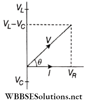
It is clear that M VL< VC i.e., if \(\omega L<\frac{1}{\omega C}\), I leads V by an angle θ.
2. In an LCR circuit, Z plays the same role as R in a pure resistive circuit. So, Z is the impedance of the circuit.
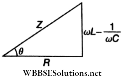
Impedance, \(Z=\sqrt{R^2+\left(\omega L-\frac{1}{\omega C}\right)^2}=\sqrt{R^2+X^2}\)
where \(X=\omega L-\frac{1}{\omega C}=X_L-X_C\) = reactance of the circuit.
Impedance in an LCR circuit is the effective resistance of the circuit arising from the combined effect of ohmic resistance and reactance of the circuit.
shows the impedance triangle for the circuit.
| Class 11 Physics | Class 12 Maths | Class 11 Chemistry |
| NEET Foundation | Class 12 Physics | NEET Physics |
Power In Series LCR Circuit:
Here, the power factor of the circuit, \(\cos \theta=\frac{R}{Z}\)
Therefore power consumed in the circuit
∴ \(P=\frac{1}{2} V_0 I_0 \cos \theta=\frac{1}{2}\left(I_0 Z\right) I_0 \cdot \frac{R}{Z}=\frac{1}{2} I_0^2 R=\left(\frac{I_0}{\sqrt{2}}\right)^2 R\)
i.e., P = I2rms R
This indicates that in this circuit power is dissipated neither in the inductor nor in the capacitor, but in the resistor only.
Hence currents through L or C are wattless.
The effective resistance of an LCR alternating current circuit is essentially the impedance of that circuit.
The inverse of impedance is known as admittance, i.e., admittance = \(\frac{1}{Z}\). Its unit is ohm” 1 or Siemens.
A pure resistance R opposes the current in any circuit and electrical energy is dissipated through it.
An inductive reactance XL and a capacitive reactance XC also oppose this current in a circuit, but no energy is dissipated through a pure inductor or a pure capacitor.
Both XL = coL and XC = depend on the frequency \(X_C=\frac{1}{\omega C}\) a) of the applied voltage. Clearly, for a dc voltage, (o = 0 . so that XL = 0, but XC = ∞. This means that dc passes freely through a pure inductor, but is blocked by a pure capacitor, which acts like an open switch.
Units of impedance and reactance: Both quantities have the same unit ohm (Ω).
Important Definitions in Alternating Current
Advantages Of The Capacitor Dependent Regulator Over A Resistor Dependent Regulator: In a resistor-dependent regulator the resistance also dissipates some energy which heats the regulator.
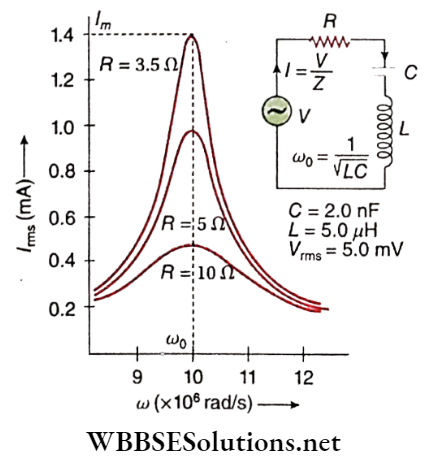
Series resonance: It is observed from equation (4) that for \(\omega L=\frac{1}{\omega C}\), the denominator becomes minimum, and hence the current I will be maximum. This phenomenon is called the series resonance of the LCR circuit. If f0 is the frequency for which the circuit reaches the above state, the condition for resonance, then
\(\omega_0 L=\frac{1}{\omega_0 C} \quad\left[\omega_0=2 \pi f_0\right]\) → (6)
i.e., \(\omega_0=\frac{1}{\sqrt{L C}}\)
or, \(f_0=\frac{\omega_0}{2 \pi}=\frac{1}{2 \pi \sqrt{L C}}\) → (7)
This frequency f0 is called resonant frequency. The particular frequency of current In an LCR series circuit for which inductive reactance (XL) and capacitive reactance (XC) become equal to each other is called resonant frequency.
Under this condition, the circuit is termed a resonant circuit. Thus, whatever the value of frequency other than f0, current I i.e., Irms is always less than its maximum value I.
The change of ac with angular frequency in an LCR circuit is shown graphically. It is known as the resonance curve. As \(I_m=\frac{V_0}{R}, I_m\) increases with the decrease of R.
Properties:
∴ \(\omega_0 L=\frac{1}{\omega_0 C} \text { or, } X_L=X_C\)
which indicates that the inductive and capacitive reactance balance each other. Hence the circuit becomes equivalent to a pure resistive circuit.
2. According to equation (5), for resonance,
∴ \(\tan \theta=\frac{0}{R}=0 \text { or, } \theta=0\)
i.e., in a resonance circuit, alternating voltage V and alternating current I are in equal phases. In this condition, according to equation (4) the maximum value of I0 i.e., Im = V0/R, which is equivalent to a pure resistive circuit.
3. LCR series circuit finds use in the receiver of a radio set. The resonant frequency of this LCR circuit is tuned with the frequency of the signal transmitted from a radio station.
Hence resonance occurs. As a result, the magnitude of the current increases a lot and the transmitted signal can easily be received. LCR series circuit is also known as acceptor circuit.
Sharpness Of Resonance And Q-Factor: Power consumed at LCR series circuit,
∴ \(P=\frac{1}{2} V_0 I_0 \cos \theta\)
where cosθ = power factor = \(\frac{R}{Z}\)
∴ \(P=\frac{1}{2} V_0 I_0 \cdot \frac{R}{Z}=\frac{1}{2} V_0 \cdot \frac{V_0}{Z} \cdot \frac{R}{Z}\)
= \(\frac{1}{2} V_0^2 \frac{R}{R^2+\left(\omega L-\frac{1}{\omega C}\right)^2}\) → (8)
At resonance, \(\omega=\omega_0 \text { and } \omega_0 L=\frac{1}{\omega_0 C}\) and as a result power dissipation becomes maximum. From equation (8) we come to the value of maximum power dissipation, i.e.,
∴ \(P_m=\frac{V_0^2 R}{2 R^2}=\frac{V_0^2}{2 R}\) → (9)
From (8) and (9) we get,
∴ \(P=P_m \cdot \frac{R^2}{R^2+\left(\omega L-\frac{L}{\omega C}\right)^2}\) → (10)
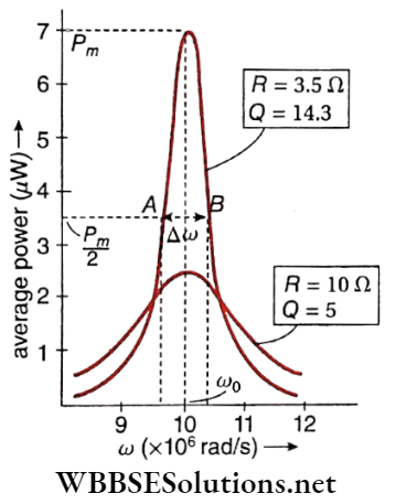
This shows the average power (P) versus frequency (ω) curve using the same circuit parameters.
The points A and B have some special importance. Each of these points denotes half maximum power \(\left(\frac{P_m}{2}\right)\).
The rapidity with which resonance phenomena arise and then disappear is a measurement of the sharpness of resonance. Resonance will be sharp if the value of bandwidth (Δω) is small.
This is of course possible only when the resonance curve falls steeply around ω = ω0.
Putting \(P=\frac{P_m}{2}\) in equation (10) we get,
= \(\frac{1}{2}=\frac{R^2}{R^2+\left(\omega L-\frac{1}{\omega C}\right)^2} \quad \text { or, }\left(\omega L-\frac{1}{\omega C}\right)= \pm R\)
or, \(\omega^2-\frac{1}{L C}= \pm \frac{R}{L} \omega\) → (11)
But we have \(\omega_0^2=\frac{1}{L C}\) (from series resonance condition)
Therefore from equation (11),
= \(\omega^2-\omega_0^2= \pm \frac{R}{L} \omega\)
i.e., \(\omega^2-\frac{R}{L} \omega-\omega_0^2=0 \quad \text { and } \omega^2+\frac{R}{L} \omega-\omega_0^2=0\)
Solving these quadratic equations neglecting the negative values of ω we get,
∴ \(\omega_1=\frac{R}{2 L}+\left(\omega_0^2+\frac{R^2}{4 L^2}\right)^{1 / 2}\)
and \(\omega_2=-\frac{R}{2 L}+\left(\omega_0^2+\frac{R^2}{4 L^2}\right)^{1 / 2}\)
Hence, bandwidth \((\Delta \omega)=\omega_1-\omega_2=\frac{R}{L}\) → (12)
and Q-factor = \(\frac{\omega_0}{\Delta \omega}=\frac{\omega_0 L}{R}=\frac{1}{\sqrt{L C}} \cdot \frac{L}{R}=\frac{1}{R} \sqrt{\frac{L}{C}}\) → (13)
Q-factor measures the sharpness of resonance in an LCR circuit. Inevitably, as Acy goes lesser, the Q-factor becomes greater and so resonance becomes sharper.
From equation (13), \(Q=\frac{\omega_0 L}{R}=\frac{X_L}{R}=\frac{I X_L}{I R}=\frac{V_L}{V_R}\)
where VL = voltage difference across inductor
and VR = voltage difference across the resistor
At resonance, VR = applied voltage ( V)
and VL = VC [VC = voltage difference across capacitor]
∴ \(Q=\frac{V_L}{V}=\frac{V_C}{V}\)
i.e., voltage difference (also called voltage drop) across inductor or capacitor concerning applied voltage in LCR series circuit is termed as Q-factor of the circuit.
The Q-factor is often much greater than 1. This means that in a series resonant circuit, VL and VC are much greater than the applied voltage V. This signifies a prominent voltage amplification across the inductor L and capacitor C.
Q-factor is a dimensionless parameter, which denotes the degree of damping of a resonator or oscillator. The more the value of Q, the less the rate of dissipation of energy concerning die energy stored, and the less the damping of the oscillator.
Example 1. In an LCR series ac circuit R = 10Ω, L = 50mH, and C = 5μV. Find out the resonant frequency and Q-factor. Find also the bandwidth and half-power frequencies.
Solution:
Here, L = 50mH = 5 x 10⁻²H;
C = 5μF = 5 X 10⁻⁶F
∴ Resonant frequency,
⇒ \(f_0=\frac{1}{2 \pi \sqrt{L C}}=\frac{1}{2 \times 3.14 \times \sqrt{\left(5 \times 10^{-2}\right) \times\left(5 \times 10^{-6}\right)}}\)
⇒ \(\frac{10^4}{2 \times 3.14 \times 5}=318.5 \mathrm{~Hz}\)
and Q-factor = \(\frac{1}{R} \sqrt{\frac{L}{C}}=\frac{1}{10} \sqrt{\frac{5 \times 10^{-2}}{5 \times 10^{-6}}}=\frac{1}{10} \times 100=10\)
Now, \(Q=\frac{\omega_e}{\Delta \omega}=\frac{f_0}{\Delta f}\)
∴ Bandwidth, \(\Delta f=\frac{f_0}{Q}=\frac{318.5}{10}=31.85 \mathrm{~Hz}\)
Half-power frequencies are,
⇒ \(f_1=f_0-\frac{\Delta f}{2}=318.5-\frac{31.85}{2}=302.6 \mathrm{~Hz}\)
and \(f_2=f_1+\frac{\Delta f}{2}=302.6+15.92=318.52 \mathrm{~Hz}\)
Example 2. In an LCR series combination, R = 400Ω, L = JOOmH, and C = 1 μF. This combination is connected to a 25 sin 2000t volt source. Find
Solution:
Applied ac voltage V = 25 sin 2000 t volt
Peak value of voltage, V0 = 25V;
angular frequency, ω = 2000 Hz
and L = 100 mH = 0.1H
So, ωL = 2000 x 0.1 =200Ω
Here, \(C=1 \mu \mathrm{F}=10^{-6} \mathrm{~F} \quad \text { So, } \frac{1}{\omega C}=\frac{10^6}{2000}=500 \Omega\)
1. Impedance of the circuit,
∴ \(Z=\sqrt{R^2+\left(\omega L-\frac{1}{\omega C}\right)^2}\)
= \(\sqrt{(400)^2+(200-500)^2}=500 \Omega\)
2. Peak value of current, \(I_0=\frac{V_0}{Z}=\frac{25}{500}=0.05 \mathrm{~A}\)
3. If the phase difference between voltage and current is θ then,
∴ \(\tan \theta=\frac{\omega L-\frac{1}{\omega C}}{R}=\frac{200-500}{400}=-\frac{3}{4}=\tan \left(-36.9^{\circ}\right)\)
i.e., current leads voltage by a phase angle of 36.9°.
4. Power factor of the circuit,
∴ \(\cos \theta=\frac{R}{Z}=\frac{400}{500}=0.8\)
5. Power dissipated,
∴ \(P=\frac{1}{2} V_0 I_0 \cos \theta=\frac{1}{2} \times 25 \times 0.05 \times 0.8=0.5 \mathrm{~W}\)
Conceptual Questions on AC Waveforms
Example 3. The power factor of an LR circuit is \(\frac{1}{\sqrt{2}}\). If the frequency of ac is doubled, what will be the power factor?
Solution:
Power factor, \(\cos \theta=\frac{R}{Z}=\frac{1}{\sqrt{2}}\)
∴ Z2 = 2R2 or, R2 + (ωL)2 = 2R2 or, (ωL)2 = R2
Now if the angular frequency co is doubled,
(ω’L)2 = (2ωL)2 = 4(ωL)2 = 4R2
So, impendance, \(Z^{\prime}=\sqrt{R^2+\left(\omega^{\prime} L\right)^2}=\sqrt{R^2+4 R^2}=R \sqrt{5}\)
Hence, power factro, \(\frac{R}{Z^{\prime}}=\frac{R}{R \sqrt{5}}=\frac{1}{\sqrt{5}}\)
Example 4. f the value of inductor L is 1 mH and the applied ac source frequency is 50 Hz, find the inductive reactance in the above case.
Solution:
Here,1 = 1 mH = 10-3 H
and ω = 2πf= 2 x 3.14 x 50 = 314 Hz
∴ XL = ωL = 314 x 10-3 = 0.314 Ω
Example 5. A series LC circuit has L = 0.405-H and C = 25 μF. The resistance R is zero. Find the frequency of resonance.
Solution:
Here, L = 0.405 H, C = 25 μF = 25 x 10-6 F
∴ \(f_r=\frac{1}{2 \pi \sqrt{L C}}=\frac{1}{2 \times 3.14 \times \sqrt{0.405 \times 25 \times 10^{-6}}}=50 \mathrm{~Hz}\)
Example 6. An inductor and a capacitor of reactances 25Ω and 75Ω, respectively, are connected across a 250 V ac source in series. Find the potential difference between the inductor and the capacitor. Establish their relationship with the main voltage.
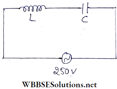
Solution:
The impedance of the series circuit having capacitor and inductor,
Z = XC-XL = (75-25) Ω = 50Ω
So, current, \(I=\frac{250}{50}=5 \mathrm{~A}\)
∴ Potential differences across the inductor,
VL = 5 x 25V = 125V
and potential differences across the capacitor,
VC = 5 x 75 V = 375 V
Now, main voltage,
V = 250 V
Hence, the relationship between V, VL and VC is
V = VC – VL
Example 7. A capacitor, a resistor of 5Ω, and an inductor of 50 mH are in series with an ac source marked 100 V, 50Hz. It is found that the voltage is in phase with the current. Calculate the capacitance of the capacitor and the impedance of the circuit.
Solution:
Since both the voltage and current of the circuit are in the same phase, the circuit is purely resistive. So impedance of the circuit, Z = R = 5 Ω
Frequency of the resonant circuit,
∴ \(f=\frac{1}{2 \pi \sqrt{L C}}\)
∴ \(C=\frac{1}{4 \pi^2 L f^2}=\frac{49}{4 \times 484 \times 50 \times 10^{-3} \times 50 \times 50}\)
= 2.03 x 10⁻⁴ F
Hence, the capacitance is 2.03 x 10⁻⁴ F and the impedance is 5Ω.
Example 8. A capacitor and a resistor are connected in series with an ac source. If the potential differences across C, R are 120 V, 90 V respectively and If the rms current of the circuit; is 3 A, calculate
Solution:
Alternating voltage in the circuit,
∴ \(V=\sqrt{V_R^2+V_C^2}=\sqrt{90^2+120^2}=150 \mathrm{~V}\)
Now, current through the circuit, I = 3 A
Example 9. A 200μF capacitor in series with a 50 Ω resistor is connected to a 220 V, 50 Hz ac source.
Solution:
Angular frequency of the source,
ω = 2πf=2 x 3.14 x 50Hz
C = 200μF = 2 x l0-4 F
Maximum current passing through the circuit
∴ \(I_0=\frac{V_0}{\sqrt{R^2+\frac{1}{C^2 \omega^2}}}\)
= \(\frac{\sqrt{2} \times 220}{\sqrt{(50)^2+\frac{1}{\left(2 \times 10^{-4}\right)^2 \times 4 \times(3.14)^2 \times(50)^2}}}\)
= 5.93 A
Now, if θ is the phase angle, then
= \(\tan \theta=\frac{1}{\omega C R}=\frac{1}{2 \pi f C R}=\frac{1}{2 \times 3.14 \times 50 \times 2 \times 10^{-4} \times 50}\)
= 0. 3185
or, \(\theta=\tan ^{-1}(0.3185)=17.67^{\circ}=\frac{17.67 \times \pi}{180} \mathrm{rad}\)
If the voltage and the current attain maximum value at a time different from t, then
θ = ωt
or, \(t=\frac{\theta}{\omega}=\frac{17.67 \times \pi}{180 \times 2 \pi \times 50}=9.82 \times 10^{-4} \mathrm{~s}\)
Example 10. A resistor, R = 300 Ω, and a capacitor, C = 25 μF are connected in series with an ac source. The peak value of voltage ( V0) and the frequency (f) of the source is 150 V and \(\frac{50}{\pi}\) Hz respectively. Find the peak value of the current and the power dissipated in the circuit.
Solution:
If ω is the angular frequency of the ac source; then
⇒ \(\frac{1}{\omega C}=\frac{1}{2 \pi \times \frac{50}{\pi} \times 25 \times 10^{-6}}=400 \Omega\)
Thus peak value of the current,
⇒ \(I_0=\frac{V_0}{\sqrt{R^2+\frac{1}{\omega^2 C^2}}}=\frac{150}{\sqrt{300^2+400^2}}=0.3 \mathrm{~A}\)
Hence, the power dissipated in the circuit
⇒ \(\frac{1}{2} I_0^2 R=\frac{1}{2} \times(0.3)^2 \times 300=13.5 \mathrm{~W}\)
WBCHSE Class 12 Physics Chapter 7 solutions
Example 11. A series LCR circuit containing a resistance of 120 Ω has an angular resonance frequency of 4 x 10⁵ rad/s. At resonance, the voltages across resistance and inductance are 60 V and 40 V, respectively. Find the values of L and C. At what frequency, does the current in the circuit lag behind the voltage by 45°?
Solution:
At resonance, XL = XC
∴ \(I=\frac{V_R}{R}\)
= \(\frac{60}{120}\) [voltage across the resistance, VR = 60 v]
= 0.5 A
Now, voltage across the inductor,
VL = IXL = IωL
∴ or, \(L=\frac{V_L}{I \omega}=\frac{40}{0.5 \times 4 \times 10^5}\) [∵ angular frequency, w = 4 x 10⁵ rad/s] [angular frequency, = 4 x 10⁵ rad/s]
= 2 x 10⁻⁴ H
We know that at resonance,
⇒ \(X_L=X_C \quad \text { or, } \omega L=\frac{1}{\omega C}\)
or, \(C=\frac{1}{\omega^2 L}=\frac{1}{\left(4 \times 10^5\right)^2 \times 0.2 \times 10^{-3}}=3.125 \times 10^{-8} \mathrm{~F}\)
Let the angular frequencyÿ ω1 when the current lags behind the voltage by 45°.
∴ \(\tan 45^{\circ}=\frac{\omega_1 L-\frac{1}{\omega_1 C}}{R}\) \(C=3.125 \times 10^{-8} \mathrm{~F}=\frac{1}{32} \times 10^{-6} \mathrm{~F}\)
or, \(1 \times 120=\omega_1 \times 2 \times 10^{-4}-\frac{1}{\omega_1\left(\frac{1}{32}\right) \times 10^{-6}}\)
or, \(\omega_1^2-6 \times 10^5 \omega_1-16 \times 10^{10}=0\)
The physically meaningful solution of the above equation is,
∴ \(\omega_1=\frac{6 \times 10^5+10 \times 10^5}{2}=8 \times 10^5 \mathrm{rad} / \mathrm{s}\)
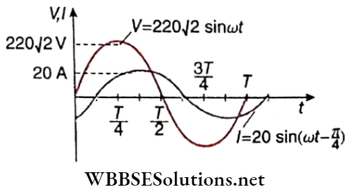
Example 12. In an LR series circuit, a sinusoidal voltage V = V0Sin ωt is applied. It is given that L = 35 mH, R = 11Ω, Vrms = 220V, \(\frac{\omega}{2 \pi}=50 \mathrm{~Hz} \text { and } \pi=\frac{22}{7}\). Find the amplitude of the current in the steady state and obtain the phase difference between the current and the voltage. Also, plot the variation of current for one cycle on the given graph.
Solution:
Inductive reactance,
∴ \(X_L=\omega L=(2 \pi)(50)\left(35 \times 10^{-3}\right) \approx 11 \Omega\)
Impedance, Z = \(\sqrt{R^2+X_L^2}=\sqrt{11^2+11^2}=11 \sqrt{2} \Omega\)
Given Vrms = 220V
Hence, amplitude of voltage, V0 = 2 Vrms = 22072 V
∴ Amplitude of current, \(I_0=\frac{V_0}{Z}=\frac{220 \sqrt{2}}{11 \sqrt{2}}=20 \mathrm{~A}\)
The phase difference between the current and the voltage in the circuit,
∴ \(\theta=\tan ^{-1}\left(\frac{X_L}{R}\right)=\tan ^{-1}\left(\frac{11}{11}\right)=\frac{\pi}{4}\)
In the LR circuit, voltage leads the current by phase angle θ. Thus current in the current circuit,
∴ \(I=I_0 \sin (\omega t-\theta)=20 \sin \left(\omega t-\frac{\pi}{4}\right)\)
In the circuit shown, S1S2S3 is a two-way switch. To charge the capacitor C first, one has to connect the switch S1S2. If S1S3 is connected, the charged capacitor and the inductance L constitute an LC circuit.
It means that the electrical energy in the capacitor has been transferred fully into the magnetic energy in the inductor.
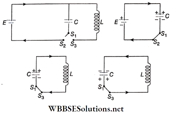
Again, due to the flow of current in the LC circuit, the capacitor is being charged in the reverse direction i.e., the capacitor is now charged with a polarity opposite to its initial state.
The energy of the capacitor is converted to the energy of the inductor and back again. This phenomenon is called LC oscillations.
In the above discussion, one half-cycle of this oscillation has been discussed. At the end of the next half-cycle, the circuit comes back to its initial condition.
Oscillators convert direct current (dc) from a power supply to an alternating current signal. LC circuits are used in many cases as an important component of an oscillator.
Example 1. A 220 V, 50 Hz ac source is connected to an inductance of 0.2H and a resistance of 20 Ω in series. What is the current in the circuit?
Solution:
rms value of current, \(I_{\mathrm{rms}}=\frac{E_{\mathrm{rms}}}{\sqrt{R^2+(\omega L)^2}}\)
Here, = 220 V,
ω = 2πf = 2 x 3.14 x 50 = 314 Hz
∴ \(\sqrt{R^2+(\omega L)^2}=\sqrt{(20)^2+(314 \times 0.2)^2}\)
∴ \(I_{\mathrm{rms}}=\frac{220}{\sqrt{(20)^2+(314 \times 0.2)^2}}=3.34 \mathrm{~A}\).
Example 2. An ac source of frequency 50 Hz is connected with a resistance (R = 36Ω) and L of 0.12 H in series. What is the phase difference between current and voltage?
Solution:
If θ is the phase difference, then
∴ \(\tan \theta=\frac{\omega L}{R}\)
or, \(\theta=\tan ^{-1} \frac{\omega L}{R}=\tan ^{-1} \frac{314 \times 0.12}{36}=\tan ^{-1}(1.047)=46.3^{\circ}\)
[here ω = 2π x 50 = 2 x 3.14 x 50 = 314 Hz]
So, phase difference = 46.3°.
Example 3. A current of 1 A flows in a coil when connected to a 100 V dc source. If the same coil is connected to a 100 V, 50 Hz ac source, a current of 0.5 A flows in the coil. Calculate the inductance of the coil.
Solution:
If R is the resistance of the coil, in dc circuit \(\frac{E}{I}=R\)
or, \(R=\frac{100}{1}=100 \Omega\)
In ac circuit, \(I_{\mathrm{rms}}=\frac{E_{\mathrm{rms}}}{\sqrt{R^2+(\omega L)^2}}\)
or, \(\sqrt{R^2+(\omega L)^2}=\frac{E_{\mathrm{rms}}}{I_{\mathrm{rms}}}=\frac{100}{0.5}=200 \Omega\)
∴ R2 + (ωL)2 = (200)2
or, \(\omega L=\sqrt{(200)^2-(100)^2}=100 \sqrt{3} \Omega\)
or, \(L=\frac{100 \sqrt{3}}{\omega}=\frac{100 \times 1.732}{2 \times 3.14 \times 50}=0.55 \mathrm{H}\)
Real-Life Scenarios in AC Circuits
Example 4. A lamp in which 10 A current can flow at 15 V is connected with an alternating source of potential 220 V and frequency 50 Hz. What should be the inductance of the choke coil required to light the bulb?
Solution:
Resistance of the lamp, \(R=\frac{15}{10}=1.5 \Omega\)
To send 10 A current through the lamp, the required impedance of the ac circuit, \(Z=\frac{220}{10}=22 \Omega\)
Now if L is the inductance of the choke coil and its resistance is negligible, then
∴ \(Z=\sqrt{R^2+(\omega L)^2} \text { or, } \omega L=\sqrt{Z^2-R^2}\)
∴ \(L=\frac{1}{\omega} \sqrt{Z^2-R^2} ;[\omega=2 \pi f=2 \times 3.14 \times 50=314 \mathrm{~Hz}]\)
= \(\frac{1}{314} \sqrt{(22)^2-(1.5)^2}=0.07 \mathrm{H}\)
Example 5. What will be the peak value of alternating current when a condenser of 1 μF is connected to an alternating voltage of 200 V, 60 Hz?
Solution:
c = 1μF = 10-6F; ω = 2πf = 2 x 3.14 x 60 Hz
Peak value of current,
\(I_0=I_{\mathrm{rms}} \times \sqrt{2}=\frac{E_{\mathrm{rms}}}{\frac{1}{\omega C}} \cdot \sqrt{2}=E_{\mathrm{rms}} \cdot \omega C \sqrt{2}\)= 200 x (2 x 3.14 x 60) x 10-6 x 1.414
= 0.106 A (approx.)
Class 12 WBCHSE Physics Alternating Current concepts
The electrical appliance used to increase or decrease alternating voltage is called a transformer.
The transformer, which increases the voltage is called a step-up transformer, and the transformer used to decrease the voltage is called a step-down transformer.
Transformer works on the principle of mutual induction between a pair of colls.
Description: The core of a transformer is constructed by several thin laminated sheets of soft iron placed one Over the other. It is known as a laminated core.
A core of a special shape is so chosen that no part of the magnetic flux is wasted and hence the density of lines of induction inside the core becomes maximum. Two insulated wires are wound in many turns on the middle arm of the core very close to each other.
Open coil acts as the primary (P) and the other as the secondary (S).
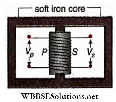
Working Principle: An alternating voltage (Vp) is applied to the primary coil from an alternating current source.
The alternating current in coil P generates induced emf in the secondary coil S, i.e., an alternating voltage Vs is generated between the ends of S.
If the dissipation of magnetic flux and loss of energy due to heating is neglected in this transformer (called an ideal transformer), it can be proved that,
∴ \(\frac{V_s}{V_p}=\frac{N_s}{N_p}=k\)
where Np and Ns are the total numbers of turps of the primary and secondary coils, respectively, and k is called the turns ratio or transformer ratio.
If Ns > Np, i.e., k > 1, Vs > Vp we get a step-up transformer.
If Ns < Np, i.e., k < 1, Vf < Vp we get a step-down transformer.
Uses: Transformers are widely used in our daily lives. With its help, a high voltage can be converted into a low voltage and vice versa, whenever necessary. For example,
Energy Loss In Transformer: In an ideal transformer, the power dissipated in the primary coil (IpVp) = power dissipated in the secondary coil (IsVs).
But no transformer, in practice, is ideal. Generally, Some input energy is wasted in any transformer and hence VsIs < VpIp .The term VsIs / VpIp is called the efficiency of a transformer.
The main causes of energy loss and their remedies are given below.
Classification Of Transformer: The two most common designs of the transformer are given below:
Core-Type Transformer: In this type, primary and secondary coils are wound around the core ring. Here every limb is occupied with both primary and secondary winding placed successively around them.
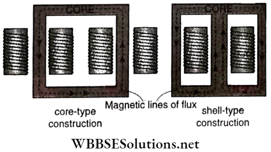
Shell-Type Transformer: Here the primary and secondary windings pass inside the steel magnetic circuit (core) which forms a shell around the windings, The main frame is constructed with three limbs. Both the primary and secondary windings are wound around the central limb.
Besides these, transformers can be classified based on their and these are audio frequency transformers, radio frequency transformers, etc.
Class 12 WBCHSE Physics Alternating Current concepts
Example 1. The number of turns in the primary aid secondary coils of an ideal transformer is 140 and 280, respectively. If the current through the primary coil is 4 A, what will be the current in the secondary coil?
Solution:
In an ideal transformer, the secondary and primary coils are equal,
i.e. VsIs ± VpIp
∴ \(I_s=I_p \cdot \frac{V_p}{V_s}=I_p \cdot \frac{N_p}{N_s}=4 \times \frac{140}{280}=2 \mathrm{~A}\)
Example 2. The initial voltage and Input power of a transformer of efficiency 80% are 100 V and 4 kW, respectively. If the voltage of the secondary coil Is 200 V, determine the currents flowing through the primary and the secondary coil.
Solution:
Power of the primary coil i.e., input power
Pp = VpIp
or, \(I_p=\frac{P_p}{V_p}=\frac{4 \times 1000}{100}=40 \mathrm{~A}\)
Power of the secondary coil, \(P_s=P_p \times \frac{80}{100}\)
Again, Ps = VsIs
So, \(I_s=\frac{P_s}{V_s}=\frac{80}{100} \times \frac{P_p}{V_s}=\frac{80}{100} \times \frac{4 \times 1000}{200}=16 \mathrm{~A}\)
Properties Of Alternating Voltage And Current
Question 1. If the frequency of an alternating emf is 50 Hz, how many times the direction of emf will be reversed per second?
Answer: 100
Question 2. What percentage of its peak value is the rms value of an ac?
Answer: 70.7
Question 3. What is the peak value of the voltage of a 220 V ac line?
Answer: 311 V
Question 4. If an alternating current is represented by I = sin l00 π mA, what is its peak value?
Answer: 1 mA
Question 5. If an alternating current is represented by, I = sin 100 πt mA, then what is the frequency of that current?
Answer: 50 Hz
Question 6. After what time will the direction of current in an electric supply of frequency 50 Hz be reversed?
Answer: 0.01 s
Question 7. An alternating source of emf E = E0 sinwt and negligible resistance is connected directly to an ac voltmeter. What reading will it show?
Answer: \(\left[\frac{E_0}{\sqrt{2}}\right]\)
Question 8. What changes are observed in the rms value of an ac with changes in the frequency
Answer: No change
Question 9. What is the rms value of an alternating current, I = I0 sin ωt?
Answer: \(\left[\frac{I_0}{\sqrt{2}}\right]\)
Question 10. What is the ratio between the peak value and the average value of a sinusoidal emf?
Answer: \(\left[\frac{\pi}{2}\right]\)
Question 11. The instantaneous i current in an ac circuit is I = 6 sin 314t A. What is the rms value of current?
Answer: 4.24 A
Question 12. An alternating current is I = cos 100 πt A. Find out its frequency, peak value, and rms value.
Answer: 50 Hz, 1 A, 0.707 A
Examples of Applications of Alternating Current
Question 13. Why a dc voltmeter and dc ammeter cannot read ac?
Answer: The average is zero in a cycle
Question 14. What will be the phase difference between current and emf when 220 V, 50 Hz ac source is connected to a circuit containing pure resistor?
Answer: Zero
Series AC Circuits With R, L, C
Question 15. What is the unit of impedance?
Answer: ohm
Question 16. What is the reactance of pressure resistances in an ac circuit?
Answer: Zero
Question 17. If an LCR circuit is connected to a dc source, what will be the current through the circuit?
Answer: zero
Question 18. What will be the reactance if a current of frequency f flows through an inductor of self-inductance L?
Answer: 2 π fL.
Question 19. What will be the reactance if a current of frequency f flows through a capacitor of capacitance C?
Answer: \(\left[\frac{1}{2 \pi f C}\right]\)
Question 20. If the frequency of an ac circuit is increased, how would the reactance of an inductor change?
Answer: Increase
Question 21. If the frequency of an ac circuit is increased, how would the reactance of a capacitor change?
Answer: Decrease
Question 22. In an LR circuit, the alternating current ________ the alternating emf by a phase current the alter angle.
Answer: Lags behind
Question 23. In a CR circuit, the alternating current ________ the alternating emf by a certain phase angle.
Answer: Lead
Question 24. In an alternating series LCR circuit, what is the phase difference between the voltage drops across L and C?
Answer: 180
Question 25. When does the LCR series circuit have minimum impedance?
Answer: At resonance
Question 26. What is the reactance of a capacitor of capacitance C at f Hz?
Answer: \(\left[-\frac{1}{2 \pi f C}\right]\)
Power In Ac Circuits
Question 27. What is the power factor of a circuit having pure resistance only?
Answer: Zero
Question 28. What is the power dissipated in an ac circuitin which voltage and current are given by \(V=230 \sin \left(\omega t+\frac{\pi}{2}\right)\) and I = I0 sinωt?
Answer: Zero
LC Oscillations
Question 29. What is the natural frequency of an LC oscillator?
Answer: \(\left[\frac{1}{2 \pi \sqrt{L C}}\right]\)
Ac Generator And Transformer
Question 30. Indicate the change in emf produced by an ac dynamo in the following cases:
Answer: Will be doubled, will decrease
Question 31. If the area of the coil of an ac dynamo is halved, how would the emf generated change?
Answer: Halved
Question 32. If the angular velocity of the coil of an ac dynamo is doubled, how would the emfproduced change?
Answer: doubled
Question 33. By what factor would the output voltage of an ac generator change, if the number of turns in its coil is doubled?
Answer: 2
Question 34. The turns ratio of an ideal transformer is 4: 1. What will be the current in the secondary if that in the primary is 1.2A?
Answer: 4.8 A
In a dynamo, mechanical energy is converted into electrical energy.
In an electric motor, electric energy is converted into mechanical energy.
The effective resistance against current in an ac circuit due to a combination of pure resistance, inductive reactance, and capacitive reactance is known as the impedance of the circuit. The magnitude of this impedance depends on the ac voltage and current.
The emf induced in a coil rotating with uniform angular velocity ω in a uniform magnetic field intensity B, about an axis perpendicular to the field is,
e = NABω sin(ωt+ α) = e0sin (ωt+α)
[The coil is of cross-sectional area A having N turns]
If the total resistance of the coil and the external circuit is R, the induced current
∴ \(i=\frac{e}{R}=\frac{\omega B A N}{R} \sin (\omega t+\alpha)=\frac{e_0}{R} \sin (\omega t+\alpha)\)
= i0sin(ωt+ α)
Equation of an alternating emf,
V = V0sin(ωt+ α) where V0 = ωABN
Equation of an alternating current,
∴ \(I=\frac{V}{R}=\frac{V_0}{R} \sin (\omega t+\alpha)=I_0 \sin (\omega t+\alpha)\)
The average values of alternating voltage and current are respectively,
∴ \(\bar{V}=\frac{2 V_0}{\pi} \text { and } \bar{I}=\frac{2 I_0}{\pi}\)
rms values of the alternating voltage and current are respectively,
∴ \(V_{\mathrm{rms}}=\frac{V_0}{\sqrt{2}} \text { and } I_{\mathrm{rms}}=\frac{I_0}{\sqrt{2}}\)
Form factor for a sinusoidal wave, \(f=\frac{V_{\mathrm{rms}}}{\bar{V}}=\frac{\pi}{2 \sqrt{2}}=1.11\)
If the number of turns in the primary coil of a transformer = Np, the number of turns in its secondary coil = Ns, and the ratio of the number of turns = k, then in the case of an ideal transformer,
∴ \(\frac{I_p}{I_s}=\frac{V_s}{V_p}=\frac{N_s}{N_p}=k\)
In an ideal transformer, input power (VpIp) = Output power ( VsIs ).
The efficiency of a transformer = \(\frac{V_s I_s}{V_p I_p}\); the efficiency of an ideal transformer = 1 or 100%.
Inductive reactance, XL = ωL.
Capacitive reactance, \(X_C=\frac{1}{\omega C}\)
The impedance of an LCR series circuit,
∴ \(Z=\sqrt{R^2+\left(\omega L-\frac{1}{\omega C}\right)^2}\)
In an LCR series circuit, if ac voltage V = V0 sin ωt then alternating current, I = I0 sin(ωt- θ),
Where \(\dot{I}_0=\frac{V_0}{Z} \text { and } \tan \theta=\frac{\omega L-\frac{1}{\omega C}}{R}\)
Condition for resonance in an LCR series circuit,
∴ \(\omega L=\frac{1}{\omega C}\)
Resonant frequency, \(f_0=\frac{1}{2 \pi \sqrt{L C}}\)
Effective voltage magnification for series resonance,
∴ \(Q=\frac{V_L}{V_R}=\frac{V_C}{V_R}=\frac{\omega_0 L}{R}=\frac{1}{\omega_0 C R}=\frac{1}{R} \sqrt{\frac{L}{C}}\)
The natural frequency of an LC oscillator,
∴ \(f=\frac{1}{2 \pi \sqrt{L C}}\)
Power dissipation in an ac circuit
= \(V_{\mathrm{rms}} I_{\mathrm{rms}} \cos \theta\)
where cos θ = power factor.
Direction: These questions have Statement 1 and Statement 2. Of the four choices given below, choose the one that best describes the two statements.
Question 1. Statement 1: The peak values by alternating voltage and alternating current in a circuit are V0 andd0 respectively.
The phase difference between voltage and current is θ. Then the power consumed is V0 I0 cosθ.
Statement 2: The consumed power in an alternating circuit depends on the phase difference between the emf and current.
Answer: 4. Statement 1 is false Statement 2 is true.
Question 2. Statement I: Q-factor of a series LCR circuit is \(\frac{1}{R} \sqrt{\frac{L}{C}}\).
Statement 2: The resonant frequency of an LCR circuit does not depend on the resistance of the circuit.
Answer: 2. Statement 1 is true, statement 2 is true; statement 2 is not a correct explanation for Statement 1.
Question 3. Statement 1: If the total energy in an LC oscillator is equally distributed between the magnetic and electric fields then the charge stored in the capacitor is \(\frac{1}{\sqrt{2}}\) fraction of the maximum charge stored in the capacitor during oscillation.
Statement 2: The charge stored in the capacitor becomes maximum at a time when the total energy of the LC circuit is stored in the electric field.
Answer: 1. Statement 1 is true, statement 2 is true; statement 2 is a correct explanation, for Statement 1.
Question 4. Statement 1: Form factor becomes different for different waveforms of alternating voltage and current
Statement 2: The mean value of alternating voltage or current = \(\frac{2}{\pi}\) x peak value and rms value = \(\frac{1}{\sqrt{2}}\) x peak value for any waveform.
Answer: 3. Statement 1 is true, Statement 2 is false.
Question 5. Statement 1: A series LCR circuit when connected to an ac source gives the terminal potential difference 50 V across each of resistor R, inductor L and capacitor C. Then the terminal potential difference across LC is zero.
Statement 2: The terminal alternating voltages across the inductor and capacitor in a series LCR Circuit in an opposite phase.
Answer: 1. Statement 1 is true, statement 2 is true; statement 2 is a correct explanation, for Statement 1.
Question 6. Statement 1: If the value of the output voltage of an ideal transformer is half the value of the input voltage, then the output current will become twice.
Statement 2: No energy is dissipated in an ideal transformer
Answer: 1. Statement 1 is true, statement 2 is true; statement 2 is a correct explanation, for Statement 1.
Question 7. Statement 1: The alternating current lags behind the voltage by a phase angle \(\frac{\pi}{2}\) when ac flows through an inductor.
Statement 2: The inductive reactance increases as the frequency of ac source decreases.
Answer: 3. Statement 1 is true, Statement 2 is false.
Question 8. Statement 1: An inductor acts as a perfect conductor for dc.
Statement 2: dc remains constant in magnitude and direction.
Answer: 2. Statement 1 is true, statement 2 is true; statement 2 is not a correct explanation for Statement 1.
Question 1. Match the columns for a series LCR circuit.
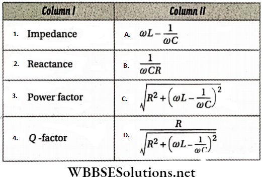
Answer: 1-C, 2-A, 3-D, 4-B
Question 2. An LCR circuit (R = 40 Ω, L = 100mH, C = 0.242 μF) is connected with an ac voltage source of peak voltage 200 V and frequency 1000 Hz.
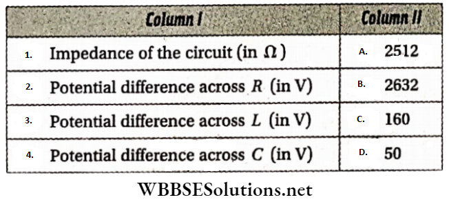
Answer: 1-D, 2-C, 3-A, 4-B
Question 3. Column I describes some action and column 2 the required device.
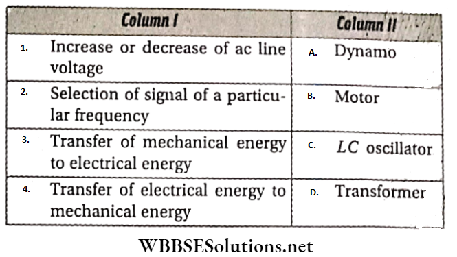
Answer: 1-D, 2-C, 3-A, 4-B
Question 4. In an LR circuit instantaneous voltage and instantaneous current are V = 100 sin100t and i = I0 sin(100t – \(\frac{\pi}{4}\) respectively.
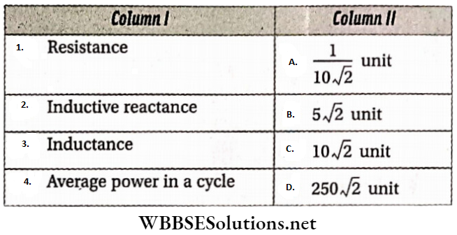
Answer: 1-B, 2-C, 3-A, 4-D
Question 5. Referring to the given circuit, match the following.
image
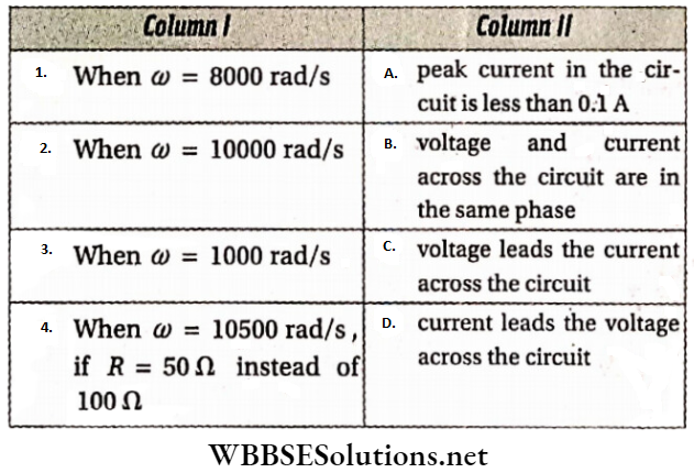
Answer: 1-A and D, 2-B, 3-A and D, 4-C
Alternating Current derivations for Class 12 WBCHSE
Read the following passage carefully and answer the questions at the end of It.
Question 1. A series combination of an inductor of self-inductance L, capacitor of capacitance C, and resistor of resistance R is connected to an alternating voltage source of V=V0 sin ωt. The current through the circuit is I = I0 sin(t-0), where \(I_0=\frac{V_0}{\sqrt{R^2+\left(\omega L-\frac{1}{\omega C}\right)^2}}\) and \(\theta=\tan ^{-1} \frac{1}{R}\left(\omega L-\frac{1}{\omega C}\right)\).
Note that, the frequency of both voltage and, current is \(f=\frac{\omega}{2 \pi}\). The rms value of these parameters during one complete cycle are \(V_{\mathrm{rms}}=\frac{V_0}{\sqrt{2}} \text { and } I_{\mathrm{rms}}=\frac{I_0}{\sqrt{2}}\) respectively. These values are shown in alternating voltmeter and ammeter.
The power consumed by the circuit P = VI. The mean value i.e., the effective power of the circuit in a complete cycle is \(\bar{P}=V_{\mathrm{rms}} I_{\mathrm{rms}} \cos \theta\). This cos θ is termed the power factor.
1. V = V0 sin ωt electromotive force is applied to an alternating circuit consisting of resistance R’ and an inductor of self-inductance L. The phase difference between the voltage and current is
Answer: 2. \(\tan ^{-1} \frac{\omega L}{R^{\prime}}\)
2. The power factor of the circuit in question (1) is
Answer: 3. \(\frac{R^{\prime}}{\sqrt{R^{\prime 2}+\omega^2 L^2}}\)
3. In the circuit in question (1) the inductor is replaced by a pure capacitor; the phase difference between the current and terminal voltage of the capacitor is
Answer: 1. -90°
4. The power factor of the circuit in question (3) is
Answer: 3. Between zero and 1
5. The voltage applied in an LCR circuit having R = 10Ω, L = 10 mH and C = 1 μF is V = 20 sin ωt volt. For what frequency of the applied voltage will the current reach Its peak value?
Answer: 2. 1592 Hz
6. The phase difference between the voltage and peak current in question (v) is
Answer: 1. Zero
7. Which element is responsible for the power consumption in an alternating current circuit?
Answer: 2. Only Inductor
8. The frequency of the applied alternating voltage In an. ac circuit is 50 Hz. The resistance and self-inductance of the circuit are 37.6 fL and 120 mH. The phase difference between the voltage and current is
Answer: 2. 45°
Question 2. A transformer is a device used to increase or decrease the voltage in the transmission line according to requirements. Generally, the input line voltage is fed into a primary coil and the output line voltage is obtained from the terminals of another coil. In an ideal transformer, the primary and secondary coils are linked in such a way that there is no loss of magnetic flux and electrical energy.
In an ideal transformer, if the number of turns and input voltage across the terminals of the primary coil are N1 and V1, then the output voltage at the two terminals of the secondary coil \(V_2=V_1 \cdot \frac{N_2}{N_1}\), where N2 is. the number of turns in the secondary coil.
1. The ratio of the number of turns of the primary and secondary coils of an ideal transformer is 2: 1. If the input voltage is 440 V, then the output voltage is
Answer: 1. 220 V
2. In question (1) if the input power of the transformer is 44 W, then the output power is
Answer: 2. 44 W
3. In the above-mentioned transformer the input and output currents are respectively,
Answer: 3. 100 mA, 100 mA
In this type, the answer to each of the questions is a single-digit integer ranging from 0 to 9.
Question 1. A resistance and a capacitor are connected in series with an alternating voltage of rms value 13 V. The terminal voltage of the resistor is 12 V and that across the capacitor is (n + 0.38) V. What is the value of n?
Answer: 6
Question 2. The current and voltage in an ac circuit are \(I=\sin \left(100 t+\frac{\pi}{3}\right) \mathrm{A}\) and V = 20 sin 100 tV. Calculate the power of the circuit in W.
Answer: 5
Question 3. In a series LCR circuit, the capacitance C is replaced by 2C. To keep the resonance frequency unchanged, the inductance has to be replaced by an inductance of L’. Find the ratio of L and L’.
Answer: 2
Question 4. An alternating voltage of 5 V of frequency 50 Hz is connected to a series LCR circuit. The potential difference across the inductor and resistor is 6 V and 4 V respectively. What is the voltage across the capacitor (in V)?
Answer: 3
Question 5. In a series LCR circuit R = 1 kΩ, C = 2μF, and the potential difference across R is 2 V. At resonance ω = 200 rad.s-1. What is the potential difference (in V) across L at resonance? across
Answer: 5
Question 6. In a series LCR circuit R = 25Ω, L = 10 mH, and C = 1μF. The circuit is connected to an AC source of variable frequency. What is the Q-factor of the circuit?
Answer: 4
Question 7. A current of 50 mA flows through a 4 μF capacitor connected to a 500 Hz ac source. The terminal potential difference (in V) across the capacitor is (η + 0.98). What is the value of η? (π = 3.14)
Answer: 3
Question 8. In the figure, an LCR series circuit is shown. What would be the ammeter reading ampere?
Answer: 8
In 1865, James Clerk Maxwell analyzed the nature of light. According to him, light is a progressive wave of an electric and a magnetic field. In other words, light is an electromagnetic wave. At this time, except for visible light, infrared, and ultraviolet, the existence of other electromagnetic waves was unknown.
As per Ampere’s circuital law (See chapter ‘Electromagnetism; section 1.5),
⇒ \(\oint \vec{B} \cdot d \vec{l}=\mu_0 I\) → (1)
But the law has a limitation. What would be the form of the above equation for a varying current I, i.e., for a varying electric field inside a conductor, is not mentioned.
For example, during the charging of a capacitor, varying current flows through the circuit though no current flows in between the plates of the capacitor. Equation (1) is not applicable in such cases.
Maxwell corrected this error by adding another term to the right side of equation (1). This additional term is,
⇒ \(\mu_0 I_d=\mu_0 \epsilon_0 \frac{d \phi_E}{d t}\) → (2)
Maxwell mentioned the quantity Jd as displacement current. Note that there is no valid reason for using the word ‘displacement’ in this context But, the word is entrenched in the language of physics.
\(\epsilon_0 \text { and } \phi_E\left(=\int \vec{E} \cdot d \vec{A}\right)\) in equation (2) is the permittivity of free space and electrical flux through a Gaussian surface respectively.
⇒ \(\oint \vec{B} \cdot d \vec{l}=\mu_0 I+\mu_0 \epsilon_0 \frac{d \phi_E}{d t}\) → (3)
which is also known as Ampere-Maxwell law.
The meaning of this expression can be understood with help. The electric flux through surface s2 is \(\phi_E=\int \vec{E} \cdot d \vec{A}=E A\), where A is the area of the capacitor plates and E is the magnitude of the uniform electric field between the plates.
If Q is the charge on the plates at any instant, then \(E=\frac{Q}{\epsilon_0 A}\).
Therefore, \(\phi_E=E A=\frac{Q}{\epsilon_0}\)
Hence, the displacement current through S2 is
∴ \(I_d=\epsilon_0 \frac{d \phi_E}{d t}=\frac{d Q}{d t}\)
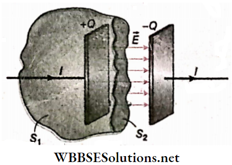
The displacement current through S2 is exactly equal to the conduction current through S1.
The displacement current can be identified as the source of the magnetic field on the surface S2. The displacement current has its physical origin in the time-varying electric field. The central point of this formalism is that a magnetic field can be produced in two ways—if
∴ The general form of Faraday’s law of induction is, \(\oint \vec{E} \cdot d \vec{l}=-\frac{d \phi_B}{d t}\).
Definition: When varying electric and magnetic fields exist in a place then these varying fields spread out in all directions like a wave which is called an electromagnetic wave.
WBBSE Class 12 Electromagnetic Waves Notes
Different types of electromagnetic waves, their wavelengths, sources, and uses are given in the following table.
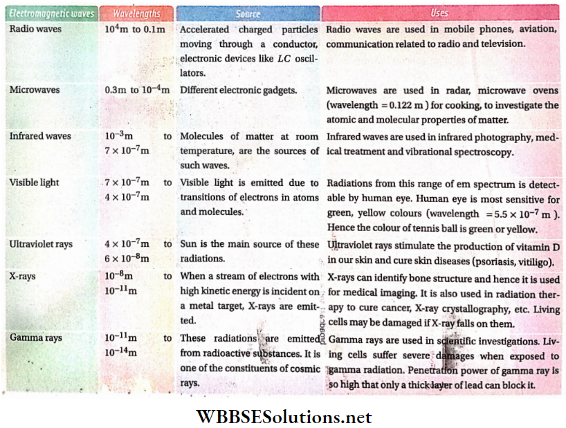
Today we know about the existence of the electromagnetic spectrum. The whole world is immersed in electromagnetic waves of different wavelengths. The sun is the main source of most of these waves.
All electromagnetic waves are generated due to the motion of accelerated charges. German physicist Heinrich Hertz, in 1888, first generated electromagnetic waves in the range of radio waves on an experimental basis.
And also made arrangements for the identification of the wave, ye took the help of an oscillating electric dipole. An oscillating electric dipole of this type is known as a Hertzian oscillator or Hertzian dipole.
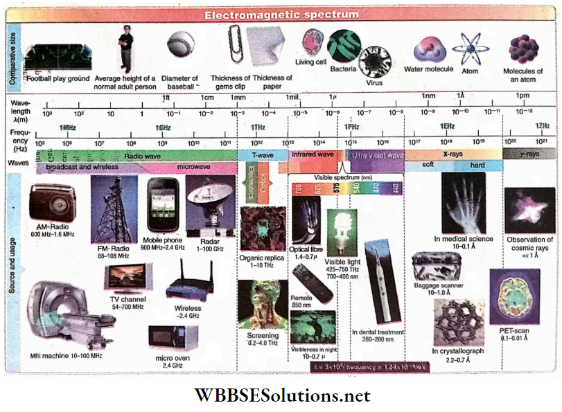
Short Notes on Electromagnetic Spectrum
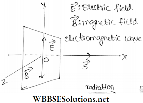
1. Electric field \(\vec(E)\) and magnetic field \(\vec(B)\) are perpendicular to the direction of propagation of the wave. Hence electromagnetic waves are transverse.
2. Magnetic field being a varying field, an electric field is induced (following Faraday’s laws of electromagnetic induction) perpendicular to it.
At the same time, varying electric fields induce a magnetic field (following Maxwell’s law of displacement current).
3. Let an electromagnetic wave propagate along the positive x direction. In that case, \(\vec{E}\) field and \(\vec{B}\) field oscillate parallel to the y and z-axes. Expressions for \(\vec{E}\) and \(\vec{B}\) fields at a distance x from the origin O are given in scalar form, by
E = E0 sin(ωt – kx) → (1)
and B = B0 sin (ωt – kx) → (2)
where E0, and B0, are the amplitudes of the electric field and magnetic field, while ω and k are the angular frequency and the magnitude of the propagation vector, respectively.
It is to be noted that none of the two fields exists independently of the other. A time-varying magnetic field induces an electric field.
Simultaneously, a time-varying electric field induces a magnetic field. Thus, self-sustaining electromagnetic waves travel through space.
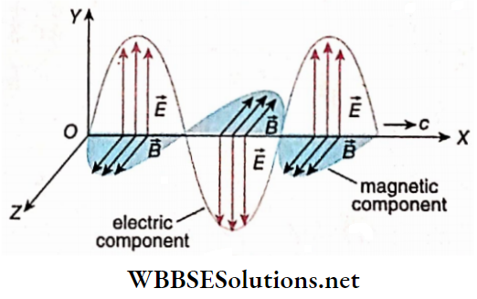
This depicts an em wave with its components along the y and z-axes oscillating in the xy-plane and zx-plane and representing equations (1) and (2) respectively. They represent the field vectors in magnitude and direction at different distances from the origin at any time t.
Equations (1) and (2) show that the frequencies of the electric and magnetic fields are equal and these two fields are always in the same phase.
Speed of electromagnetic wave in free space,
⇒ \(c=\frac{1}{\sqrt{\mu_0 \epsilon_0}}\) → (3)
where μ0 and ε0 are respectively permeability and permittivity of free space.
Here, = μ0 x 10-7 N. s2.C-2
ε0 = 8.854 X 10⁻² C2. N-2. m-2
Substituting the values in equation (3) we get,
⇒ \(c=\frac{1}{\sqrt{4 \pi \times 10^{-7} \times 8.854 \times 10^{-12}}}=2.998 \times 10^8\)
≈ 3.0 x 10² m. s-1
In addition, the velocity of an electromagnetic wave can also be obtained from the amplitudes of electric and magnetic fields as,
⇒ \(\frac{E_0}{B_0}=c\) → (4)
From equations (1) and (2) we get,
∴ \(\frac{E}{B}=\frac{E_0}{B_0}=c\)
If the frequency and the wavelength of an electromagnetic wave in a medium are respectively f and λ, then in that medium the velocity of the wave will be fλ. If the medium changes, the wavelength as well as the velocity will change, but the frequency will remain the same because frequency is a characteristic of the source.
| Class 11 Physics | Class 12 Maths | Class 11 Chemistry |
| NEET Foundation | Class 12 Physics | NEET Physics |
Some Quantities Related To EM Waves
Energy density: We have seen that the electric field, E = E0sin(ωt – kx), and magnetic field, B = B0 sin (ωt – kx).
Consider a volume element dV of the medium in which an electromagnetic wave is propagating. At a certain moment, the energy carried by the volume is U. As the energy stored is due to both electric and magnetic fields, we have
U= UE+UM
Here, UE = stored energy due to the electric field in the volume element dV
= \(\frac{1}{2} \epsilon_0 E^2 \cdot d V\)
UM = stored energy due to magnetic field in the volume element dV
= \(\frac{1}{2} \frac{B^2}{\mu_0} \cdot d V\)
So, at any position x of the electromagnetic wave at time t, the energy density of the electric field,
∴ \(u_E=\frac{U_E}{d V}=\frac{1}{2} \epsilon_0 E^2=\frac{1}{2} \epsilon_0 E_0^2 \sin ^2(\omega t-k x)\)
The energy stored in a unit volume of the space between two plates of a charged air capacitor, \( u_=\frac {1}{2} c_0 E^2[/atex].
We can prove that the total stored energy of the charged capacitor = uE x volume of the space between two plates of capacitor = [latex]\frac{1}{2} C V_{P d}^2\), where, C = capacitance of the capacitor and VP(t = potential difference between the plates of the capacitor.
and the energy density of the magnetic field,
∴ \(u_M=\frac{U_M}{d V}=\frac{1}{2 \mu_0} B^2=\frac{1}{2 \mu_0} B_0^2 \sin ^2(\omega t-k x)\)
The above equation is used to calculate the energy, stored in an inductor.
Average value of sin2# or cos2# in a complete cycle = \(\frac{1}{2}\)
Here, \(\left\langle\sin ^2(\omega t-k x)\right\rangle=\frac{1}{2}\)
Therefore, the average energy density,
⇒ \(\bar{u}_E=\frac{1}{2} \epsilon_0 E_0^2 \times \frac{1}{2}=\frac{1}{4} \epsilon_0 E_0^2\)
and \(\bar{u}_M=\frac{1}{2 \mu_0} B_0^2 \times \frac{1}{2}=\frac{1}{4 \mu_0} B^2=\frac{1}{4} c^2 \epsilon_0\left(\frac{E_0}{c}\right)^2\)
= \(\frac{1}{4} \epsilon_0 E_0^2\) [∵\(c=\frac{1}{\sqrt{\epsilon_0 \mu_0}} \text { or } \frac{1}{\mu_0}=c^2 \epsilon_0\)]
so \(\bar{u}_E=\bar{u}_M\)
It implies that the energy is equally distributed between electric and magnetic fields during the propagation of electromagnetic waves.
The average energy density of electromagnetic waves,
∴ \(\bar{u}=\bar{u}_E+\bar{u}_M=\frac{1}{4} \epsilon_0 E_0^2+\frac{1}{4} \epsilon_0 E_0^2=\frac{1}{2} \epsilon_0 E^2\)
For a complete cycle, the average value can be written as u instead of \(\bar{u}\).
Hence energy density,
⇒ \(u=\frac{1}{2} \epsilon_0 E^2=\frac{1}{2 \mu_0} B_0^2\) → (1)
In general, for an isotropic medium of permittivity ε, the energy density,\(u=\frac{1}{2} \epsilon E_0^2\), where ε = Kε0, K is the dielectric constant of the medium.
Practice Problems on Wave Equations
Intensity: In an electromagnetic field, if we consider a unit area around a point, perpendicular to the direction of radiation, then the electromagnetic energy incident on that area per second is called the intensity of electromagnetic radiation at that point.
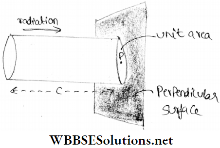
Let P is a point in an electromagnetic field. The wave propagates toward the point P with velocity c. A unit area is considered around P, which is perpendicular to the direction of propagation of radiation.
In time dt, the wave travels a distance equal to cdt in the direction of propagation. Imagine a cylinder of length cdt and unit cross-sectional area on the path of the wave such that it crosses the cylinder normally.
The energy of the electromagnetic wave incident at point P is equal to the energy stored in the volume of the imaginary cylinder (cdt X 1 = cdt).
The intensity of radiation at P is equal to the energy incident per second i.e., the energy stored in the volume, c x 1 = c.
So, the energy contained in that cylinder =cu, where u = energy density.
Therefore, the intensity of electromagnetic wave at the point P, by definition
I = cu
By using the equation (l), we get,
⇒ \(I=c u=\frac{1}{2} c \epsilon_0 E_0^2=\frac{1}{2 \mu_0} c B_0^2\) → (2)
Incidentally, unlike in mechanical waves, this energy flow per unit area, per unit time, called energy flux is denoted by S, not I.
Hence, \(S=\frac{d u}{A d t}=c u\)
Average value S is given by \(\bar{S}=\frac{1}{2 \mu_0} E_0 B_0=\frac{1}{2} \epsilon_0 c E_0^2\)
\(\vec{S}\) called Poynting vector, is given by \(\vec{S}=\frac{1}{\mu_0}(\vec{E} \times \vec{B})=\vec{E} \times \vec{H}\)
The direction of \(\vec{S}\) is given by the direction of propagation of the wave, as shown.
If the point P is considered in an isotropic medium of electric permittivity ε and permeability μ instead of free space, then the equation (2) will be
∴ \(I=v u=\frac{1}{2} v \epsilon E_0^2=\frac{1}{2 \mu} v B_0^2\)
Where, \(v=\frac{1}{\sqrt{\epsilon \mu}}\) = velocity of the electromagnetic radiation in tha medium.
Unit of the intensity of electromagnetic radiation
= J.m-2.s-1 = W.m-2
Its dimension = \(\frac{M L^2 T^{-2}}{L^2 T}=M T^{-3}\)
Radiation Pressure: EM wave has linear momentum as well as energy. This means that radiation can exert force and hence pressure on any surface on which it is incident during Its propagation through a medium.
The force exerted on a unit area of the surface, perpendicular to the direction of propagation is called radiation pressure.
From thermodynamical analysis, we can show that (this analysis is beyond our syllabus),
Radiation pressure,\(p=\frac{1}{3} u\). where u = energy density of electromagnetic radiation [see the equation (1)].
The unit of pressure (p) = N.m-2; the unit of energy density
(u) = J.m-3.
Generally, both the units are the same as N.m = J.
The dimension of both p and u = ML-1T-2.
The force due to the radiation pressure is too small to detect under everyday circumstances. In subjects, like astronomy or astrodynamics-related works, its importance cannot be ignored.
For example, if the radiation pressure of the sun had been ignored, the space crafts, Viking-1 and Viking-2 (sent by NASA to Mars’s orbit to collect information about Mars) would have missed Mars’s orbit by about 15000 km.
Example 1. If the velocity of the em wave in a vacuum is 3 x 10⁸ m.s-1 and the -magnetic permeability of the vacuum is 4π x 10-7 N.C-2. s2, find the electric permittivity of the vacuum.
Solution:
If permittivity and permeability of free space are ε0 and μ0, respectively,
∴ \(c=\frac{1}{\sqrt{\epsilon_0 \mu_0}} \quad \text { or, } c^2=\frac{1}{\epsilon_0 \mu_0}\)
∴ \(\epsilon_0=\frac{1}{\mu_0 c^2}=\frac{1}{4 \pi \times 10^{-7} \times 9 \times 10^{16}}\)
[∵ μ0 = 4π x 10-7 N.C-2. s2 and c = 3 x 10⁸ m.s-1]
= 8.842 x 10⁻¹² C2.N-1 m-2
Example 2. The amplitude of the electric field of a plane electromagnetic wave is 48 V.m-1. What is the amplitude of the magnetic field of the wave?
Solution:
In this case, the amplitude of the electric field
E0 = 48 V.m-1
As \(\frac{E_0}{B_0}=c\) amplitude of magnetic field, \(B_0=\frac{E_0}{c}\)
∴ \(B_0=\frac{48}{3 \times 10^8}\) [∵ c = 3 x 10⁸ m.s-1]
= 16 x 10-8 Wb.m-2
Important Definitions in Electromagnetic Theory
Example 3. The electric field of an electromagnetic wave is, E = 10-5 sin(12 x 1015 t-4 x 10⁷x). Find the frequency, velocity, and wavelength of the wave. Write the equation of the magnetic field corresponding to this wave. Assume all quantities in SI unit.
Solution:
The electric field of the given electromagnetic wave,
E = 10-5 sin(12 x 1015 t – 4 x 10⁷x)
Compared with the expression for the electric field,
E = E0sin(ωt – kx) we get,
ω = 12 x 1015 rad.s-1
∴ 2πf = 12 x 1015
or \(f=\frac{12 \times 10^{15}}{2 \pi}=1.9 \times 10^{15} \mathrm{~Hz}\)
Hence, the frequency of the wave, f = 1.9 x 10¹⁵ Hz.
The velocity of the wave,
⇒ \(v=\frac{\omega}{k}=\frac{12 \times 10^{15}}{4 \times 10^7}=3 \times 10^8 \mathrm{~m} \cdot \mathrm{s}^{-1}\)
Wavelength \(\lambda=\frac{c}{f}=\frac{3 \times 10^8}{1.9 \times 10^{15}}=1.58 \times 10^{-7} \mathrm{~m}\)
Equation of the corresponding magnetic field,
⇒ \(B=B_0 \sin (\omega t-k x)=\frac{E_0}{c} \sin (\omega t-k x)\) [∵\(\frac{E_0}{B_0}=c\)]
⇒ \(\frac{10^{-5}}{3 \times 10^8} \sin \left(12 \times 10^5 t-4 \times 10^7 x\right)\)
∴ 3.33 x 10⁻¹⁴ sin(12 x 1015 t-4 x 10⁷x)T
Example 4. In an electromagnetic Held, the amplitude of the electric field at a point is 3 V m-1. Calculate the energy density and Intensity of the wave at that point. Given μ0 = 4π x 10-7H. m-1
Solution:
The amplitude of the electric field, E0 = 3 V. m-1
⇒ \(B_0=\frac{E_0}{c}=\frac{3}{3 \times 10^8}=10^{-8} \mathrm{~Wb} \cdot \mathrm{m}^{-2}\)
So, the energy density,
⇒ \(u=\frac{1}{2 \mu_0} B_0^2=\frac{1}{2 \times 4 \pi \times 10^{-7}} \times\left(10^{-8}\right)^2\)
⇒ 3.98 x 10⁻¹¹J . m-3
Intensity, I = cu = (3 x 108) x (3.98 x 10-11)
= 0.012 W. m-2
Examples of Applications of Electromagnetic Waves
Example 5. A rectangular parallel plate capacitor of dimension 5 cm x 4 cm is charged in such a way that the rate of change of electric field between the two plates is 5.65 x 10¹¹V. m-1 . s-1. Calculate the displacement current for this capacitor.
Given ε0 = 8.85 x 10⁻¹² F. m-1
Solution:
Area of a rectangular plate,
A = (5 x 4) cm2 = 20 cm2 = 0.002 m2
If E is the electric field between two plates, then the electric flux,
⇒ \(\phi_E=E A ; \frac{d \phi_E}{d t}=A \frac{d E}{d t}\)
Therefore, the displacement current,
⇒ \(I_d=\epsilon_0 \frac{d \phi_E}{d t}=\epsilon_0 A \frac{d E}{d t}\)
= (8.85 x 10-12) x 0.002 x (5.65 x 1011)
= 0.01 A = 10 mA
Example 6. Calculate the intensity and the rms value of an electric field of an electromagnetic wave at a distance of 10 m from a 100 W electric bulb.
Given ε0 = 8.85 x 10⁻¹² F. m-1
Solution:
Area of a spherical surface of radius 10 m
A = 4π (10)2 = 400 m2
∴ Intensity, I, \(\frac{100 \mathrm{~W}}{400 \pi \mathrm{m}^2}=\frac{1}{4 \pi} \mathrm{W} \cdot \mathrm{m}^{-2}=0.08 \mathrm{~W} \cdot \mathrm{m}^{-2}\)
Here, \(I=\frac{1}{2} c \epsilon_0 E_0^2=c \epsilon_0 E_{\mathrm{rms}}^2\) [latex]E_{\mathrm{rms}}=\frac{E_0}{\sqrt{2}}[/latex]
∴ \(E_{\mathrm{rms}}=\sqrt{\frac{I}{c \epsilon_0}}=\sqrt{\frac{0.08}{\left(3 \times 10^8\right) \times\left(8.85 \times 10^{-12}\right)}}\)
= 5.5 V. m-1
Conceptual Questions on Maxwell’s Equations
Displacement Current
Question 1. The current which comes into play in a region where the electric flux is changing with time is called___________.
Answer: Displacement Current
Question 2. Write down the mathematical form of Ampere-Maxwell’s law.
Answers: \(\oint \overrightarrow{B \cdot} \cdot d \vec{l}=\mu_0 I+\mu_0 \epsilon_0 \frac{d \phi_E}{d t}\)
Electromagnetic Spectrum
Question 3. The wavelength of a radio wave is 10 m. Is this statement true or false?
Answer: True
Question 4. Wavelengths of visible light, X-rays, and infrared rays are λ1, λ2, and λ3, respectively. Arrange them in ascending order of their magnitudes.
Answer: λ2, λ1, λ3
Question 5. Of X-rays, γ-rays, and ultraviolet rays, which one has the maximum frequency?
Answer: γ – ray
Question 6. Which part of the electromagnetic spectrum has the largest penetrating power?
Answer: Gamma rays
Question 7. Name the electromagnetic waves that have frequencies greater than those of ultraviolet light but less than those of gamma rays.
Answer: x-rays
Question 8. Find the wavelength, in angstrom unit, of electromagnetic waves of frequency 5 x 10¹⁹Hz in free space.
Answer: 0.06 A
Production And Propagation Of Electromagnetic Waves
Question 9. An electromagnetic wave is propagating along the positive z-axis. At any moment, if the direction of the magnetic field at a point is along the positive x-axis, what will be the direction of the electric field at that point?
Answer: Along the negative y-axis
Question 10. What is the velocity of a radio wave in a vacuum?
Answer: 3 x 10⁸ m. s-1
Question 11. Light is a progressive wave of _______ and _______ fields.
Answer: Electric, magnetic
Question 12. An electromagnetic wave is a _______ progressive wave
Answer: Transverse
Question 13. Write down the relation among the velocity of electromagnetic waves, the magnetic permeability of vacuum, and the electric permittivity of vacuum.
Answer: \(c=\frac{1}{\sqrt{\mu_0 \epsilon_0}}\)
Question 14. A Physical quantity is expressed by the ratio of the amplitudes of electric and magnetic fields for an electromagnetic wave.
Answer: velocity of the wave
Question 15. What is the ratio of velocities of light rays of wavelengths 4000A and 8000A in a vacuum?
Answer: 1:1
Question 16. What is the ratio of speeds of infrared rays and ultraviolet rays in a vacuum?
Answer: 1:1
Question 17. Which physical quantity, if any, has the same value waves belonging to the different parts of the electromagnetic spectrum?
Answer: Speed in vacuum
Electromagnetic waves exhibit wave wave-like nature as they travel through space.
Electromagnetic wave has both oscillating electric and magnetic field components.
An LC circuit connected with an AC source is known as an LC oscillator. With the help of an LC Oscillator, electromagnetic waves can be created.
The energy is equally distributed between electric and magnetic fields at the time of propagation of electromagnetic waves in a medium.
Real-Life Scenarios in Electromagnetic Wave Experiments
The velocity of electromagnetic waves in free space,
⇒ \(c=\frac{1}{\sqrt{\mu_0 \epsilon_0}}\)
where μ0 and ε0 are permeability and permittivity of free space respectively.
If μ0 = 4π x 10-7N.C-2. s2;
and ε0 = 8.854 x 10⁻¹² C2.N-1.m-2 then, c = 3.0 x 10⁸m.s-1
If the amplitudes of electric and magnetic fields are E0 and B0 respectively, then
⇒ \(\frac{E}{B}=\frac{E_0}{B_0}=c\)
The energy density of an electromagnetic field,
⇒ \(u=\frac{1}{2} \epsilon_0 E_0^2=\frac{1}{2 \mu_0} B_0^2\)
The intensity of radiation at an OOOpoint in an electromagnetic field,
I = cu
and radiation pressure,
∴ \(p=\frac{1}{3} u\)
Direction: These questions have statement 1 and statement 2. Of the four choices given below, choose the one that best describes the two statements.
Question 1. Statement 1: The electric field 1 and the magnetic field 3 are mutually perpendicular at a point in the electromagnetic wave.
Statement 2: Electromagnetic waves are transverse waves.
Answer: 2. Statement 1 is true, and statement 2 is true; statement 1 is not a correct explanation for statement 1.
Question 2. Statement 1: Electromagnetic waves are transverse waves.
Statement 2: Electromagnetic waves have the property of polarisation.
Answer: 1. Statement 1 is true, statement 2 is true; statement 2 is a correct explanation for statement 1.
Question 3. Statement 1: The ratio of the amplitudes of electric and magnetic fields at a point in the electromagnetic wave is the same as the velocity of the wave.
Statement 2: If a medium, μ, and ε are the magnetic permeability and the electric permittivity respectively, then 1/ √με is the velocity of an electromagnetic wave in that medium.
Answer: 4. Statement 1 is false, statement 2 is true.
Question 4. Statement 1: During the propagation of visible light and X-rays as electromagnetic waves, X-rays carry more energy than visible light despite both of them having the same amplitudes of electric fields at a point.
Statement 1: The frequency of X-rays is much higher than that of visible light.
Answer: 2. Statement 1 is true, and statement 2 is true; statement 2 is not a correct explanation for statement 1.
Question 5. Statement 1: During the propagation of electromagnetic wave along the z-axis, if the electric field \(\vec{E}\) at a point is along the x-axis, then the magnetic field B at that point will be along the y-axis.
Statement 2: In the direction of propagation of the electromagnetic wave, the electric field \(\vec{E}\) and the magnetic field \(\vec{B}\) both form a right-handed cartesian coordinate system.
Answer: 3. Statement 1 is true, and statement 2 is false.
Question 1. Some types of electromagnetic waves and their corresponding frequencies are given in column 1 and column 2 respectively.
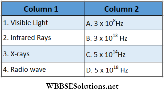
Answer: 1-C, 2-B, 3-D, 4-A
Question 2. Some quantities and their corresponding dimensions are given in Column 1 and Column 2 respectively.
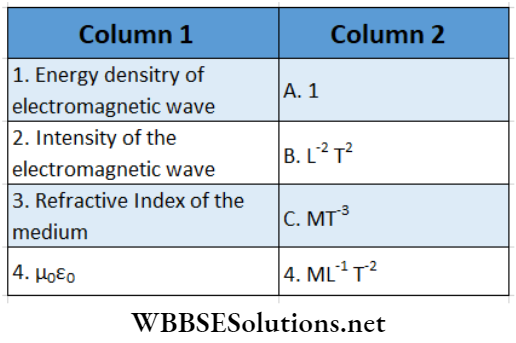
Answer: 1-D, 2-C, 3-A, 4-B
Question 1. Electromagnetic waves propagate through free space or a medium as transverse waves. The electric and magnetic fields are perpendicular to each other as well as perpendicular to the direction of propagation of waves at each point. In the direction of wave propagation, electric field \(\vec{E}\) and magnetic field \(\vec{B}\) form a right-handed cartesian coordinate system. During the propagation of electromagnetic waves, the total energy of electromagnetic waves is distributed equally between electric and magnetic fields. Since e0 and are permittivity and permeability of free space, the velocity of electromagnetic wave, c = (ε0μ0)-1/2. Energy density i.e., energy volume due to electric field at any point, \(u_E=\frac{1}{2} \epsilon_0 E^2\); Similarly, energy density due to magnetic field, \(u_M=\frac{1}{2 \mu_0} B^2\). If the electromagnetic wave propagates along x -direction, then the equations of electric and magnetic field are respectively,
E = E0sin(ωt- kx) and B = B0sin(ωt-kx)
Here, the frequency and the wavelength of oscillating electric and magnetic fields are \(f=\frac{\omega}{2 \pi}\) and \(\lambda=\frac{2 \pi}{k}\) respectively. Thus \(E_{\mathrm{rms}}=\frac{E_0}{\sqrt{2}}\) and \(B_{\mathrm{rms}}=\frac{B_0}{\sqrt{2}}\), where \(\frac{E_0}{B_0}=c\). Therefore, average energy density, \(\bar{u}_E=\frac{1}{2} \epsilon_0 E_{\mathrm{rms}}^2\) and \(\bar{u}_M=\frac{1}{2 \mu_0} B_{\mathrm{rms}}^2\). The intensity of the electromagnetic wave at a point, \(I=c \bar{u}=c\left(\bar{u}_E+\bar{u}_B\right)\).
To answer the following questions, we assume that in the case of propagation of an electromagnetic wave through free space, c = 3 x 10⁸ m. s-1 and μ0 = 4 π x 10-7 H. m-1
Question 1. If the electromagnetic wave propagates along the x-axis, then the electric field \(\vec{E}\) will be
Answer: 4. Along y-axis
Question 2. If the peak value of the electric field at a point in an electromagnetic wave is 15 V.m-1, then the average electrical energy density (in J.m-3)
Answer: 3. 4.98 x 10⁻¹⁰
Question 3. The peak value of the magnetic field (in Wb.m-2) at that point
Answer: 1. 5 x 10⁻⁸
Question 4. The average energy density (in J.m-3 )of the electromagnetic wave at that point
Answer: 4. 9.95 x 10⁻¹⁰
Question 5. The intensity (in W.m-2) of the electromagnetic wave at that point is almost
Answer: 2. 0.3
Question 6. If the wavelength is 1000A, then the frequency (in Hz)
Answer: 4. 3 x 10¹⁵
Question 7. Relation between ω and k
Answer: 1. \(\omega=c k\)
In this type, the answer to each of the equations is a single-digit integer ranging from 0 to 9.
Question 1. If the dielectric constant and relative magnetic permeability of a medium are 4 and 2.25 receptively, then the velocity of an electromagnetic wave in that medium is n x 108m.s-1. Find the value of n.
Answer: 1.
Question 2. When the frequency of an electromagnetic wave and the amplitude of its associated magnetic field at a point are 108HZ and 10-10 T respectively, then the amplitude of the electric field is n x 10-2 V . m-1. Find the value of n.
Answer: 3.
Question 3. Due to the sunlight, if the amplitude of the electric field at the earth’s surface is 900 V m-1, then the amplitude of the magnetic field is n x 10-6 T. Find the value of n.
Answer: 3.
Question 4. What is the wavelength (in meters) of a radio wave of frequency 1.5 x 10⁸ HZ?
Answer: 2.
Question 5. If the intensity of an electromagnetic wave at a point is 0.085 W m-2, then find the average amplitude (in V.m-1) of the electric field at that point.
Answer: 8.
When a current-carrying wire is placed in a magnetic field, it is deflected, i.e., a motion is generated. An opposite phenomenon was first observed by Michael Faraday.
He saw that if a closed wire loop is moved in a magnetic field, an electric current is generated in that loop as long as the motion continues.
Definition: If there is a relative motion between a magnetic field and a conductor, an electromotive force is generated in the conductor. It is called induced electromotive force.
It should be noted carefully that, to get electric current from this induced emf, the conductor should be in the form of a closed circuit.
This is because, the resistance of an open circuit is infinite and hence, despite the presence of induced emf, no current passes through the conductor.
Definition: If there is a relative motion between a magnetic field and a closed circuit conductor, the current flowing through that conductor is known as induced current.
Electromagnetic induction: The phenomenon involving the generation of electrical energy due to relative motion between a magnetic field and a conductor is called electromagnetic induction.

Induced current with the help of a magnet: In Fig. 1.1, C is a circular coil having one or more turns. M is a permanent magnet kept along the axis of C. G is a galvanometer connected to C.
By observing the deflection of the pointer in G towards left or right, the direction of current in the coil C (i.e., anticlockwise or clockwise) can be determined.
Again, noting the extent of deflection of the pointer (i.e.,
low or high), the magnitude of the current, low or high, can be ascertained.
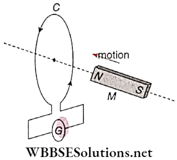
For different motions of the magnet along the axis of the coil, the directions of induced current through the coil are given in the following table.
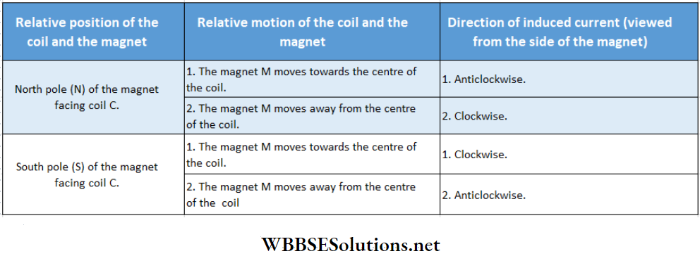
WBBSE Class 12 Electromagnetic Induction Notes
Note that, no induced current is noticed in the coil when
Direction Of The Induced Electromotive Force:
This direction depends on
Magnitude Of The Induced Electromotive Force:
Magnitude And Direction Of The Induced Current:
Note that, induced electromotive force does not depend on the resistance of the circuit. In an open circuit, the resistance is infinite, hence no current passes but the induced emf associated with the circuit does exist.
Current Induced With The Help Of Current Carrying Conducting Coil Or Current Carrying Solenoid:
A current-carrying circular coil or a current-carrying solenoid is equivalent to a permanent magnet. The rule for determination of their poles are
So, if a circular current-carrying coil or a current-carrying solenoid is used instead of the magnet M shown, the same experimental result will be obtained. Two more important facts should be noted:
Current Induced With The Help Of Static Electrical Circuits:
In S is a circular coil with one or more turns. A galvanometer G is connected to it. From this galvanometer, the magnitude and direction of the induced current can be determined.
P is another co-axial circular coil connected with an electrical circuit. B is a battery and a key K is used to switch on or off the circuit. Again, with the help of the rheostat, current through the circuit can be increased or decreased.
Now, if the circuit P be switched ‘on’ or if the current in the circuit is increased rapidly, the magnetic field also increases considerably.
It is similar to the situation when a magnet is moved towards the coil S swiftly. So, the results of two phenomena: ‘increase of current in the circuit P’ and ‘relative motion between the coil S and the magnetic field’ are identical.
Naturally, if the circuit P is switched ‘off’ suddenly or if the current in the circuit is decreased rapidly, the effective relative velocity becomes just opposite to the former case.
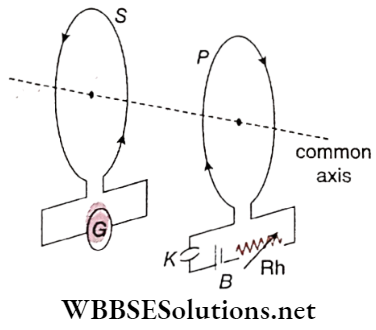
Observation:
the current through coil P be increased or decreased in different ways using the key K and the rheostat Rh, the induced current found the coil S will be as described below:
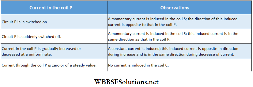
Short Notes on Faraday’s Law of Induction
Primary And Secondary Coils:
In the experiment shown, the current through coil P is the cause of electromagnetic induction and this coil is called the primary coil.
On the other hand, the current in coil S is the result of electromagnetic induction and this coil is called the secondary coil.
From the discussion of magnetism we know that, if a magnetic material is placed in an external magnetic field, it gets magnetically induced.
This magnetic induction is a vector quantity, and the most convenient way to specify its magnitude and direction is to draw lines of induction through that substance.
If the magnetic induction is greater at a place, lines of induction get crowded there. Moreover, the direction of lines of induction is to be represented.
According to the direction of magnetic induction at every point. From this we can define magnetic induction as follows:
Definition: The number of lines of induction passing normally through a unit area surrounding a point inside a substance is called magnetic induction at that point.
Magnetic induction is a vector quantity, its symbol is \(\vec{B}\). This vector is identical to the magnetic field \(\vec{B}\) described in the chapter ‘Electromagnetism.
Usually, the lines of induction passing through any medium are called lines of force. These continuous lines of force passing through a medium can be imagined as a kind of stream.
This stream is comparable to the flow of water. We know that, in the case of water flow, the rate of flow of water can be obtained from the mass of water passing through any cross-section. Magnetic flux can be defined from this analogy.
Definition: The number of lines of induction passing normally through any surface placed in a magnetic field is called the magnetic flux linked with that surface.
Magnetic flux is a scalar quantity, and its symbol is Φ.
Let the area of a surface placed in a uniform magnetic field be A. If the magnetic induction \(\vec{B}\) is inclined at an angle θ with the normal to the surface, the component of \(\vec{B}\) in the direction of that normal is Bcosθ (magnitude of \(\vec{B}\) is B).
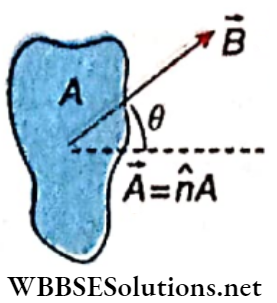
Hence according to the definition, of magnetic flux,
⇒ \(\phi=B A \cos \theta=\vec{B} \cdot \vec{A}=\vec{B} \cdot \hat{n} A\)
where \(\hat{n}\) is a unit vector normal to the surface.
For a finite surface, we first consider the magnetic flux through an infinitesimal area \(d \vec{A}\). The magnetic flux across this area, \(d \phi=\vec{B} \cdot d \vec{A}\)
A finite surface A can be assumed as the summation of such infinitesimal elements and the magnetic flux through the total surface area,
∴ \(\phi=\int_S \vec{B} \cdot d \vec{A}\)
Special Cases:
If the lines of induction are along the surface, then θ = 90° and hence Φ = 0.
If the lines of induction are perpendicular to the surface, θ = 0° and hence Φ = BA. In this case, \(B=\frac{\phi}{A}\) = magnetic flux linked with unit area.
Thus, magnetic induction \(\vec{B}\) is also called magnetic flux density. According to this flux is positive.
If θ = 180°, Φ = -BA i.e., flux is negative.
The phenomenon of electromagnetic induction is completely described by three laws. The exact information obtained from these laws is as follows:
Faraday’S Laws
First law: Whenever the magnetic flux linked with a coil changes with time, an electromotive force is induced in the coil. Induced EMF lasts as long as the magnetic flux linked with the coil continues to change.
Second law: The magnitude of the induced is directly proportional to the time rate of change of magnetic flux linked with the coil.
If the change in magnetic flux linked with a coil in time dt be dtb, according to Faraday’s second law,
induced emf \(e \propto \frac{d \phi}{d t}\) → (1)
Explanation Of Faraday’s Two Laws: The magnetic lines of force or lines of. induction adjacent to the north pole (IV) of a bar magnet M is shown.
Explanation Of The First Law:
If a closed coil is moved from A to A’ or from A’ to A, the number of lines of force through that coil, i.e., magnetic flux linked with it decreases or increases, respectively.
According to Faraday’s first law, during the motion of the coil in both cases an emf will be induced in the coil: On the other hand, if the coil is at rest, no change in the magnetic flux will occur, and hence induction will not take place.
From the experiment of electromagnetic induction, the same result is obtained. So, from the first law, the cause of the electromagnetic induction and the time of existence of the induced emf can be ascertained.
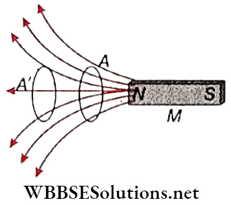
Explanation Of The Second Law: If the relative velocity between the coil and the magnet is increased, the strength of induced emf also increases. This phenomenon is by Faraday’s second law, because if the coil is moved quickly the rate of change of the number of lines of force, i.e., the rate of change of magnetic flux also increases. So, the second law determines the magnitude of the induced emf.
Lenz’s Law
From Faraday’s laws, the direction of the induced emf cannot be ascertained. The necessary law for the determination of this direction is Lenz’s law. This may be called the third law of electromagnetic induction.
Statement: In the case of electromagnetic induction, the direction of the induced emf is such that, it always opposes the cause of induction in the circuit.
Important Definitions in Electromagnetic Induction
Explanation of Lenz’s law:
Relative motion between a magnet and a closed coil:
Let C be a circular conducting coil. Along its axis, the north pole (AO of a bar magnet M is moved towards the coil.
According to Lenz’s law, the induced current in C will oppose the motion of the magnet M, i.e., it will repel the magnet. For this, a north pole would be generated on the front face of the coil.
So, if viewed from the side of the magnet, the induced current will be anticlockwise. Similarly, if the magnet is moved in the opposite direction the current in the coil C will be clockwise.
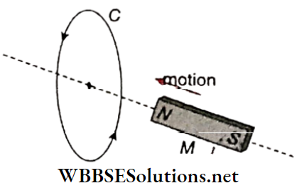
If magnet M is moved forward beyond the surface of coil C, the induced current in the coil will attract the south poles of the magnet.
Hence, a north pole should be generated on the back face of the coil and a south pole on the front face. So, if Viewed from the front face, the induced current is clockwise.
Primary And Secondary Coils:
let a current be passed through the primary coil P by switching on the circuit. At that moment.
The instantaneous effect on the secondary coil becomes similar to the effect due to a sudden rapid movement of a current-carrying coil towards the secondary coil.
So, according to Lenz’s law, the induced current in the secondary coil S will repel the primary coil. Since two unlike parallel currents repel each other.
We can conclude that the induced current in the secondary coil is opposite in direction concerning the primary coil.
On the other hand, if the primary circuit is switched off; just at that moment, a like current will be induced in the secondary coil.
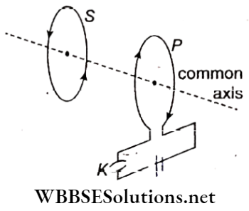
Falling Of A Magnet Through A Coil: when a body is allowed to fall freely in the gravitational field of the earth, it falls with „ acceleration due to gravity (g).
Let us consider a closed circular coil C kept horizontally and along its axis, a bar magnet M is released. Due to the downward motion of the magnet, an induced current is set up in coil C.
According to Lenz’s law, the direction of this induced current will be such that, the downward motion of the magnet will be opposed. As a result, the magnet will fall with a smaller acceleration than that due to gravity (g).
If the coil is replaced by a long cylindrical conductor (say, a copper pipe), the slower motion of the magnet becomes more dearly noticeable.
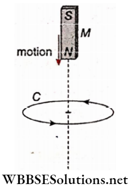
Lenz’s Law From The Law Of Conservation Of Energy:
Let a bar magnet M be moving towards a closed coil C along its axis. Its north pole faces the coil. As a result, a current is induced in the coll, i.e., electrical energy is developed.
According to the law of conservation of energy, this electrical energy can only be obtained at the cost of other forms of energy and hence some external positive work is to be done against an opposing force.
The current induced in the coil is the source of this opposing force. Naturally, the direction of the induced current has to be anticlockwise to develop.
An N pole in its front face will oppose the motion of the bar magnet. So, Lenz’s law is a natural consequence of the law of conservation of energy.
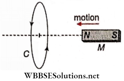
Law Of Conservation Of Energy From Lenz’s Law:
According to Lenz’s law, the direction of the induced emf is such that, this induced emf can oppose the cause of the generation of electric current in the circuit.
It means that if we gradually bring a magnet near the coil, the induced EMF will oppose the forward motion, and when the magnet is taken away from the coil, it opposes that receding motion.
As a result, to generate relative motion between the magnet and the coil, some work must be done against this opposing force and this work will induce electromotive force to obey the principle of conservation of energy.
Hence, the principle of conservation of energy can be obtained from Lenz’s law.
Expression For Induced Electromotive Force
From Faraday’s second law we know that, if the change in magnetic flux linked with a closed conductor be dtp in time dt, induced emf, \(e \propto \frac{d \phi}{d t}\)
So, according to Lenz’s law, we can write,
\(e=-k \frac{d \phi}{d t}\) → (1)
Here, k is a positive constant. Since the induced emf e opposes the change in magnetic flux dΦ, a negative sign is used in the equation.
Note that, equation (1) expresses the three laws of electromagnetic induction simultaneously.
Units Of Magnetic Flux And Magnetic Induction:
The unit of magnetic flux is so defined that the magnitude of the
constant k in equation (1) becomes 1
For \(e=1, \text { if } \frac{d \phi}{d t}=1, \text { then } k=1\)
In that case \(e=-\frac{d \phi}{d t}\) → (2)
So, the unit of magnetic flux is defined as the change in unit time of magnetic flux linked with a conducting coil, for which 1 unit emf is induced in that coil.
Again, since the magnetic flux linked with the unit area is called magnetic induction or magnetic flux density, the unit of magnetic induction or magnetic flux density = \(\frac{\text { unit of magnetic flux }}{\text { unit of area }}\)
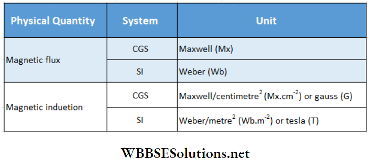
1 Wb: The change of magnetic flux linked with a coil in 1 s, for which 1 V emf is induced in the coil, is called 1 Wb.
In other words, 1 Weber is the magnetic flux which, linking a circuit of one turn, would produce in it an electromotive force of 1 volt if it were reduced to zero at a uniform rate in 1 second.
1 Mx: The change of magnetic flux linked with a coil in 1 s, for which 1 abvolt (1 abvolt = 10~8 V) emfis induced in the coil, is called 1 Mx.
In other words, 1 maxwell is the magnetic flux which, linking a circuit of one turn, would produce in it an electromotive force of 1 aibvolt if it were reduced to zero at a uniform rate in 1 second.
Relation Between Different Units:
As l volt = 108 abvolt
so, 1 Wb = 108 Mx .
Again, 1 T = \(\frac{1 \mathrm{~Wb}}{1 \mathrm{~m}^2}=\frac{10^8 \mathrm{Mx}}{10^4 \mathrm{~cm}^2}\)
= 104 Mx.cm-2 = 104 G
Relation between web and V: According to the relation,
⇒ \(e=\frac{d \phi}{d t}\),
∴ \(\mathrm{V}=\frac{\mathrm{Wb}}{\mathrm{s}}\) or, Wb = V.s
Amount Of Change Flowing Through A Closed Circuit For Induced Electromotive Force:
Let the number of turns of any closed coil be n, the emf induced in the coil be e and the rate of change of magnetic flux linked with the coil be \(\frac{d \phi}{d t}\). Now, if the resistance of the circuit is R, the current induced in it (taking the magnitude only),
∴ \(i=\frac{e}{R}=\frac{n}{R} \cdot \frac{d \phi}{d t}\) [∵ e = \(n \frac{d \phi}{d t}\)]
Or, \(i d t=\frac{n}{R} \cdot d \phi\) → (3)
If the initial magnetic flux linked with the coil be and the final magnetic flux linked be <p2, then integrating equation (3) we get,
⇒ \(\int_0^t i d t=\frac{n}{R} \int_{\phi_1}^{\phi_2} d \phi=\frac{n}{R}\left(\phi_2-\phi_1\right)\)
So, the amount of charge flowing through the circuit,
∴ \(q=\int_0^t i d t=\frac{n}{R}\left(\phi_2-\phi_1\right)\) → (4)
Example 1: A coil of resistance 100 Ω having 100 turns is placed in a magnetic field. A galvanometer of resistance 400 Ω is connected in series with it If the coil is brought from the present magnetic field to another magnetic field in \(\frac{1}{10}\)s, determine the average emf and the current. Given, the initial and final magnetic flux linked with each turn of the coil are 1 mWb and 0.2 mWb respectively.
Solution:
Change in magnetic flux for each turn
= 0.2-1 = -0.8 mWb
So, a change in magnetic flux for 100 turns
= 100 X (+0.8) mWb = -0.08 Wb
Hence, the magnitude of average emf-induced
= the negative of the rate of change of magnetic flux
= \(-\left(-\frac{0.08 \mathrm{~Wb}}{\frac{1}{10} \mathrm{~s}}\right)=0.8 \mathrm{~V}\).
The equivalent resistance of the circuit = 100 + 400 = 500 Ω
Hence, the average induced current = \(\frac{0.8 \mathrm{~V}}{500 \Omega}\) = 0.0016 A = 1.6mA.
Practice Problems on Electromagnetic Induction
Example 2. A conducting wire is wound around the great circle of a spherical Balloon. This Circular Loop Can Contract with The Balloon. A hemispherical cross-section of the balloon is shown in the figure. The initial radius of the balloon is 0.60m. A uniform magnetic field B = 0.25T exists along the perpendicular to the plane of the circular loop., in +y – direction. After 5.0 x 10⁻², the balloon is deflated to a radius of 0.30m. What will be the average EMF induced in the loop during this time?
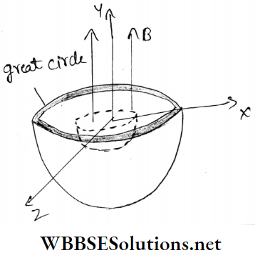
Solution: Initially the flux linked with the conducting loop along the y-axis,
⇒ \(\phi_i=\vec{B} \cdot \overrightarrow{A_i}=B A_i \cos 0^{\circ}=0.25 \pi \times 0.60^2\)
= 0.28 Wb
After deflation of the balloon, the flux linked with the conducting loop of radius 0.30m,
⇒ \(\phi_f=\vec{B} \cdot \vec{A}_f=B A_f \cos 0^{\circ}=0.25 \pi \times 0.30^2\)
= 0.070 Wb
∴ change of flux,
∴ \(\Delta \phi=\phi_f \phi_i=(0.070-0.28) \mathrm{Wb}=-0.21 \mathrm{~Wb}\)
∴ Induced emf, e = \(e=-\frac{\Delta \phi}{\Delta t}=\frac{+0.21}{5 \times 10^{-2}}=4.2 \mathrm{~V}\).
| Class 11 Physics | Class 12 Maths | Class 11 Chemistry |
| NEET Foundation | Class 12 Physics | NEET Physics |
Example 3. A copper wire of diameter 0.04 in. and length 50 cm is bent in the form of a circular loop. The plane of the loop is normal to a uniform magnetic field which is increasing with time at a constant rate of 100 G.s-1. What is the rate of Joule heating in the loop? [Resistivity of copper = 1.7 X l0-8 Ω . m, 1 in. = 2.54 cm]
Solution:
The radius of the wire
= 0.02 in. = 0.02 x 2.54 x 10-2m = 5.08 x 10⁻⁴ m
Area of cross-section of the wire,
⇒ \(A_1=\pi r^2=\pi\left(5.08 \times 10^{-4}\right)^2=81 \times 10^{-8} \mathrm{~m}^2\)
Resistance of the wire,
⇒ \(R_0=\frac{\rho l}{A_1}=\frac{1.7 \times 10^{-8} \times 0.5}{81 \times 10^{-8}} \Omega\) [l =length of the wire = 0.5 m ]
= 1.05 x 10⁻² Ω
The radius of the loop,
⇒ \(R=\frac{l}{2 \pi}=\frac{0.5}{2 \pi}=7.96 \times 10^{-2} \mathrm{~m}\)
Area of the loop,
⇒ \(A=\pi R^2=3.14 \times\left(7.96 \times 10^{-2}\right)^2\)
= 0.02 m2
Here \(\frac{d B}{d t}=100 \mathrm{G} / \mathrm{s}=10^{-2} \mathrm{~Wb} \cdot \mathrm{m}^{-2} \cdot \mathrm{s}^{-1}\)
∴ Induced emf,
⇒ \(e=A \cdot \frac{d B}{d t}=(0.02) \times 10^{-2}=2 \times 10^{-4} \mathrm{~V}\)
∴ From Joule’s law, the rate of Joule heating,
⇒ \(H=I^2 R_0=\frac{e^2}{R_0}=\frac{\left(2 \times 10^{-4}\right)^2}{1.05 \times 10^{-2}}=3.8 \times 10^{-6} \mathrm{~W}\)
Let us assume a uniform magnetic field \(\vec{B}\) directed along the axis which is vertically downwards.
A rod PQ parallel to the z -z-axis, is moving at a constant velocity \(\vec{v}\) along the x -x-axis through this field.
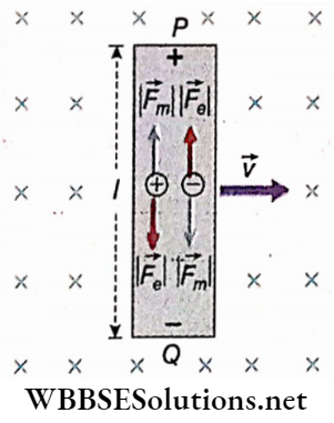
In this condition, a free charge q in the rod experiences a magnetic force, \(\vec{F}_m=q \vec{v} \times \vec{B}\). If q is a positive charge then this force is directed from Q to P (i.e., along +ve z-axis).
On the other hand, if q is negative then this force is directed from P to Q (i.e., along the -ve z-axis). Hence the free charges continue to accumulate at the ends of the rod creating a gradually increasing potential difference between P and Q.
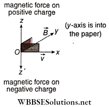
This, in turn, creates an increasing electric field \(\vec{E}\) within the rod, in the direction from P to Q (opposite to the magnetic force). Due to this growing electric field, the electric force exerted on the charge q at any moment, Fe = qE.
As the magnitude of electric force comes to be equal with that of magnetic force, no net force anymore acts on the charge q, i.e., at equilibrium condition,
⇒ \(\left|\vec{F}_e\right|=\left|\vec{F}_m\right|\)
i.e., \(q|\vec{E}|=q|\vec{v} \times \vec{B}| \quad \text { or, }|\vec{E}|=|\vec{v} \times \vec{B}|\)
∴ \(E=v B \quad\) [∵ \(\vec{v} \perp \vec{B}]\)→ (1)
Let the potential difference between the ends P and Q be V. If the length of the rod is l then,
V = El = vBl [putting the value of E from (1) ] → (2)
Now, if the ends of the rod are connected with a conductive wire, a current is set up in the circuit. Hence the moving rod can be considered as a source of emf (e), i.e., as a cell. Just like in a cell, this emf directs from the negative end Q to the positive end p inside the road.
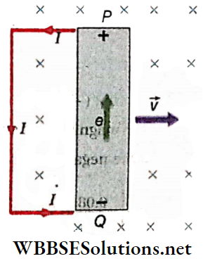
For an open circuit, equation (2) can be written as,
V = e = vBl → (3)
This induced EMF in the moving rod is called motional electromotive force.
In general, if θ is the angle between \(\vec{v}\) and \(\vec{B}\) then, equation (3) becomes,
e = vBlsinθ → (4)
Discussions:
Dependence Of Induced Motional Emf On Different Factors:
From the above equation (4), the emf e induced across the straight conductor moving in a magnetic field is
For θ = 90°, the emf induced is maximum.
Emf Induced Between The Two Extremities Of The Wings Of An Aeroplane:
At different places on the earth, the geomagnetic field is not horizontal; from the values of the angle of dip, the actual direction of the geomagnetic field is known.
When an aeroplane flies in a horizontal plane above the earth’s surface, the length of its two wings repeatedly intercepts the lines of force of the geomagnetic field.
As a result, electromagnetic induction takes place, i.e., a potential difference is set up between the two extremities of its wings.
The magnitude of this potential difference depends on
The value of the angle of dip at the geomagnetic equator is zero. In this position, a horizontally moving aeroplane does not cut the geomagnetic lines of force, and hence no potential difference is set up between the extremities of the wings.
Emf Induced Between The Two Ends Of A Conductor Rotating With Uniform Angular Velocity In A Uniform Magnetic Field:
Let a conductor of length L be rotating about the point O with uniform angular speed ω in the plane of the paper. The magnetic field B is normally upwards relative to the plane of the paper.
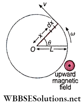
Let us consider a small element dx of the conductor at a distance x from the point 0, which is moving with velocity v perpendicular to the direction of the magnetic field. The emf induced in this element of the conductor,
de = B(dx)v [using the relation, e = Blv]
= Bωxdx [∵ v = ωx]
So, the emf induced between the two ends of the entire conductor,
∴ \(e=\int_0^L B \omega x d x=B \omega\left[\frac{x^2}{2}\right]_0^L=\frac{1}{2} B \omega L^2\)
Induced Current In A Moving Straight Conductor:
In the discussion of motional electromotive force, if R be the total resistance of the circuit then, V = IR. So, from (3) we get,
⇒ \(I R=v B l \quad \text { or, } I=\frac{v B l}{R}\) → (5)
The direction of the induced current can be determined with the help of the following simple rule.
Fleming’s right-hand rule:
The thumb, the forefinger and the middle finger of the right hand are stretched perpendicular to each other.
If the magnetic field forefinger points in the direction of the magnetic field and the thumb in the direction of the motion of the conductor, then the middle finger will point in the direction of the induced current.
This rule is also called the dynamo rule.
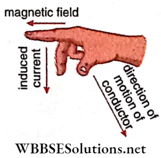
Example 1. The distance between the two endpoints of the wings of an aeroplane is 5m and the aeroplane is flying parallel to the earth’s surface with a velocity of 360 km h-1. If the geomagnetic intensity is 4 x 10⁻⁴ Wb.m-2 and the angle of dip at that place is 30°, determine the emf induced between the two end-points of the wings.
Solution:
While flying horizontally, the wings of the aeroplane cut the vertical component of the earth’s magnetic field normally and hence, an emf is induced between the two ends of the wings.
This induced emf, e = Blvsinθ.
Here \(B=4 \times 10^{-4} \mathrm{~Wb} \cdot \mathrm{m}^{-2}, l=5 \mathrm{~m}\)
⇒ \(v=360 \mathrm{~km} \cdot \mathrm{h}^{-1}=360 \times \frac{5}{18} \mathrm{~m} \cdot \mathrm{s}^{-1}=100 \mathrm{~m} \cdot \mathrm{s}^{-1}\)
and θ = 30°.
∴ e = 4 x 10-4 x 5 X 100 x sin30° = 0.1 V
Example 2. A copper disc of diameter 20 cm is rotating uniformly about its horizontal axis passing through the centre with an angular frequency of 600 rpm. A uniform magnetic field of strength 10-2 T acts perpendicular to the plane of the disc. Calculate the induced emf between its centre and a point on the rim of the disc.
Solution:
The diameter of the disc = 20 cm
∴ Radius, r = 10 cm = 0.1 m
Angular frequency, n = 600 rpm
∴ Angular speed,
⇒ \(\omega=\frac{600 \times 2 \pi \mathrm{rad}}{60 \mathrm{~s}}=20 \pi \mathrm{rad} \cdot \mathrm{s}^{-1}\)
Let us take a small segment dx on the disc at a distance x from its centre. The length of dx is so small that the speed of all the points on this segment is considered to be the same, which is, v’ = ωx.
Therefore, motional emf across dx,
de = v’Bdx [where B is the magnetic field]
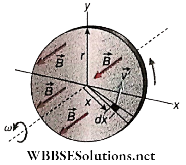
∴ Total induced emf between the centre and a point on the rim of the disc,
∴ \(e=\int_0^r \nu_B^{\prime} B d x=\int_0^r \omega x B d x=\frac{1}{2} \omega B r^2\)
⇒ \(\frac{1}{2} \times 20 \pi \times 10^{-2} \times(0.1)^2\)
∴ 0.00314 V = 3.14 mV
Examples of Applications of Electromagnetic Induction
Example 3. A pair of parallel horizontal conduct invariable resistance shorted at one end Is fixed on a smooth table. The distance between the rails Is L. A massless conducting rod of resistance R can slide on the rails frictionlessly. The rod is tied to a massless string which passes over a pulley fixed to another edge of the table. A mass m, tied to the other end of the string, hangs vertically. A constant magnetic field B exists along the perpendicular to the plane of the table in an upward 1 direction. If the system Is released from rest, calculate
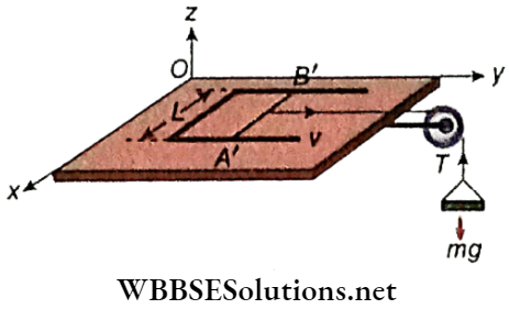
Solution:
1. Let, rod A’B’ of length L and resistance R slide with a velocity v along the y-axis, while a constant magnetic field B exists along the z-direction.
Induced emf in the rod, e = BLv
The induced current flowing through the rod,
⇒ \(I=\frac{e}{R}=\frac{B L v}{R}\)
The direction of flow of the current through the rod A’B’ will be such that, it opposes the cause of generation of induced emf i.e., the motion of the rod along a positive y-axis. Thus the rod will experience force along the negative y-axis. The magnitude of the force is given by,
⇒ \(F=B I L=B \cdot \frac{B L v}{R} \cdot L=\frac{B^2 L^2 v}{R}\)
Let the rod move with acceleration, along the positive y-axis. Then from the equation of motion,
⇒ \(m a=m g-F=m g-\frac{B^2 L^2 v}{R} \quad \text { or, } a=g-\frac{B^2 L^2 v}{m R}\)
When the rod gets terminal velocity v0, then a = 0
∴ \(0=g-\frac{B^2 L^2 v_0}{m R}\)
∴ \(v_0=\frac{m g R}{B^2 L^2}\)
2. When the rod moves with velocity, \(v=\frac{1}{2} v_0\), then
⇒ \(v=\frac{m g R}{2 B^2 L^2}\)
Hence the acceleration of the mass at the instant
∴ \(a=g-\frac{B^2 L^2}{m R} \cdot \frac{m g R}{2 B^2 L^2}=g-0.5 g=0.5 g\)
To enhance the effect of electromagnetic induction, in many cases, solid plates of soft iron or rods are used as the core of the armatures rotating in a magnetic field.
For example, in a dynamo, the armature rotating in the magnetic field is wound on a core of soft iron. Now, iron is a good conductor of electricity.
So electromagnetic induction takes place over the entire volume of the iron rotating in the magnetic field.
Many closed circuits or loops are formed locally within iron and induced current continues to flow in each loop.
Such current is known as eddy current Generally eddy current is produced whenever a conducting metal plate is in motion in a magnetic field.
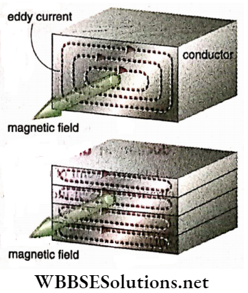
If there is a relative motion between a conducting metal piece and a magnetic field, an induced current is set up throughout the volume of the metal in different closed loops. This current is known as eddy current.
According to Lenz’s law, eddy current opposes the cause that produces it, i.e., it opposes the relative motion between the metallic conductor and the magnetic field.
Due to this opposition, heat is generated in the conductor. This wasteful thermal energy comes at the cost of useful energy.
To minimise the loss of energy in the form of heat due to eddy current the cores are not taken as a single piece but are made of many thin laminas ofconductors which are insulated from each other with suitable insulating materials.
By doing so, the flux linked with local eddy current circuits is reduced to a minimum, hence eddy current becomes quite weak and its heating effect is minimised.
On calculation, it is observed that if the number of lamina is n instead of a single one, the loss of energy due to eddy current will come down to \(\frac{1}{n}\) times.
On the other hand, eddy current in some cases can be applied in our favour. For example, the coil of a moving coil galvanometer when deflected in the magnetic field begins to oscillate around the equilibrium position.
It takes a long time to come to rest To get rid of this problem the coil is wound on a single soft iron core.
The eddy current thus produced in the core opposes the motion of the coil following Lenz’slaw. Thus, the coil will not oscillate for a long time after the current is cut off.
It will return to the equilibrium position quickly. Besides this, eddy current is employed usefully in induction motors, induction cookers, electric brakes, etc.
Self Induction
When current flows through a coil, a magnetic field is generated around the coil. As a result, the coil becomes linked up with its magnetic flux.
This magnetic flux Increases or decreases with the increase or decrease of current. Hence, an electromagnetic induction takes place and an emf is induced in the coil.
This induced emf opposes the change in electric current through the coil. This phenomenon is known as self-induction.
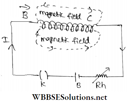
Definition: An electromagnetic induction in a coil due to a change of current through itself is called self-induction.
The electric current generated due to self-induction flows in the direction opposite to the main current.
Self-Inductance: If current flows through a coil, the magnetic flux linked with the coil becomes directly proportional to the current passing through it. So, if the magnetic flux is <p for current I, then
Φ ∝ I or, Φ = LI →(1)
L is a constant which depends on its construction. It is called the self-inductance or coefficient of self-induction of the coil. If I = 1, then L = Φ.
Definition: For unit current flowing through a coil, the magnetic flux linked with it is called its self-inductance.
Again, we know that the emf induced in the coil, \(e=-\frac{d \phi}{d t}\)
So, using equation (1) we can write,
\(e=-L \frac{d I}{d t}\) → (2)
If \(\frac{d I}{d t}=1\), then e = L (considering the magnitude only). From this, the following alternative definition of self-inductance can be drawn:
If the rate of change of electric current in a coil with time is unity, the emf induced in the coil is called its self-inductance.
Unit Of Self-Inductance:
In SI: In this system, the unit of self-inductance is Henry (H). To define it, we can use either of the equations (1) or (2).
So, the self-inductance of a coil is 1 H if
Hence, from equation (1) we get
Wb = H.A → (3)
Again from equation (2) we get
⇒ \(V=H \cdot \frac{A}{s} \quad \text { or, } \frac{V}{A} \cdot s=H\)
∴ H = Ω.s → (4)
The unit of resistance R is Ω and the unit of self-inductance L is H. Hence from equation (4) we infer that the unit of \(\frac{L}{R}\) and the unit of time is the same.
In CG System: Putting \(\frac{d I}{d t}=1 \mathrm{emu} \cdot \mathrm{s}^{-1}\) and e = 1 emu of emf, we get, L = 1 emu of self-inductance. So, if the current is changed at the rate of 1 emu.s-1 and 1 emu electromotive force is induced in the coil, the self-inductance of that coil is 1 emu.
Relation between the CGS and SI units of self-inductance:
⇒ \(1 \mathrm{H}=\frac{1 \mathrm{~V}}{1 \mathrm{~A} \cdot \mathrm{s}^{-1}}=\frac{10^8 \mathrm{emu} \text { of potential difference }}{\frac{1}{10} \text { emu of current per second }}\)
= 109 emu of inductance
Non-inductive Coil: Self-induction creates disturbances in many electrical circuits. A coil of finite resistance but of zero self-inductance is often required. Such a coil is called a non-inductive coil.
A long insulated conducting wire is given a fold and then coiled up. The free ends of the coil are now on the same side. This kind of winding is called non-inductive winding.
Hence antiparallel currents flow through adjacent wires of any part of the coil. So, the resultant magnetic flux becomes zero. That means, in this coil, no electromagnetic induction takes place.

Effect Of Self-Induction On Electrical Circuit:
In the circuit, if the emf of battery B is E, the effective emf of the circuit due to self-induction [according to equation (2)] = \(E-L \frac{d I}{d t}\)
If the current is zero or a steady current flows through the circuit, \(\frac{d I}{d t}=0\); and in this case, self-induction does not affect the circuit.
On the other hand, self-induction affects a circuit when electric current changes with time in that circuit.
Thus, self-induction plays an important role in an AC circuit. In the case of a DC circuit, self-induction occurs only when the circuit is switched ‘on’ or ‘off.
Choke: A coil of high self-inductance and low resistance is commonly called a choke. If a choke is connected in series in an AC circuit, then due to its high self-inductance, the effective resistance of the circuit increases.
On the other hand, due to the low resistance of the coil, less heat is produced in the circuit. So, the function of a choke is to increase the effective resistance of the circuit lowering the dissipation of heat energy as much as possible.
Uses: In a tube light arrangement, a choke is usually connected in series.
Energy stored In the magnetic field of an inductor: We have induced emf in an inductor carrying a time-varying current i, \(e=-L \frac{d i}{d t}\), where L = self-inductance of the inductive coil.
To increase the current in the inductor against this opposing emf, some energy has to be spent on work. This external work will be stored in the magnetic field of the inductor as magnetic energy.
Power, i.e., rate of work done = ei = \(L i \frac{d i}{d t}\) (the negative sign is not taken in calculation of work done)
So, work done in time dt = ei dt = Lidi
Total work done to increase the current through the inductor from 0 to I,
⇒ \(W=L \int_0^I i d i=L \cdot\left[\frac{i^2}{2}\right]_0^I=\frac{1}{2} L I^2\)
This work done is stored as energy (EL) in the magnetic field of the inductor, i.e.,
∴ \(E_L=\frac{1}{2} L I^2\)
Mutual Induction
Let two coils, P and S, be kept very close to each other. Now if current is passed through them (say, P), a magnetic field is generated around it.
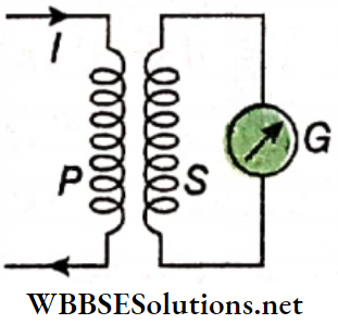
As a result, the second coil (S) gets linked with the magnetic flux generated by the first coil. If the current through P is increased or decreased concerning time.
The magnetic flux linked with an electromotive force induced in the coil S will also increase or decrease accordingly. Hence, an electromotive force is induced in the coil S.
This phenomenon is known as mutual induction. The first coil P is called the primary coil and the second coil S is called the secondary coil.
Definition: If current changes over time in a coil, the electromagnetic induction that occurs in an adjacent coil is called mutual induction.
Mutual Inductance: Mutual inductance is defined in a similar way as self-inductance. If the magnetic flux linked with the secondary coil is Φs for the current Ip in the primary coil then,
⇒ \(\phi_S \propto I_P \quad \text { or, } \phi_S=M I_P\) → (1)
Here, M is a constant, which depends on the geometry of the coils and the distance between them and is called mutual inductance or coefficient of mutual induction.
Naturally for Ip = 1, M = Φs
Definition: In the case of two adjacent coils, if one carries a unit current, then the magnetic flux linked with the other is called the mutual inductance between the two coils.
Again, induced emf in the secondary cop,
⇒ \(e=-\frac{d \phi_S}{d t}=-M \frac{d I_P}{d t}\) → (2)
If \(\frac{d I_p}{d t}=1\), then e = M [considering the magnitude only]
From this, the following, an alternative definition of mutual inductance is obtained.
In the case of two adjacent coils, if the rate of change of current concerning time in a coil is unity, the emf induced in the other coil is called the mutual inductance between the two coils.
Unit Of Mutual Inductance:
In SI: In this system, the unit of mutual inductance is Henry (H), exactly that of self-inductance L.
‘Mutual inductance between a pair of coils is 1 H’ means that,
In the CGS system: If \(\frac{d I}{d t}=1\) emu of current per second and e = 1 emu of potential, then M = 1 emu of mutual inductance. So, in the case of two adjacent coils, if the current changes at the rate of 1 emu.s-1 in one coil and as a result if 1 emu of emf is induced in the other coil, the mutual inductance between the coils is said to be 1 emu.
Discussions:
Interchange of two colls: The second coil can be used as the primary coil and the first as the secondary. In that case, due to: a change in current in the second coil, electromagnetic induction will take place in the first coil, and the value of mutual, inductance (M) will remain unchanged.
Relation between self-inductance, and mutual inductance: If the self-inductances of the two coils are, L1 and L2, the mutual inductance becomes
⇒ \(M=k \sqrt{L_1 L_2}\) (3)
Here, k is a constant whose value is 1 or less than 1. If the magnetic flux of one coil is linked completely with the other; k≈1. Thus,
∴ \(M \approx \sqrt{L_1 L_2}\)
Self-inductance of a solenoid: Let the length of the solenoid = l, area of its circular cross-section = A.
So, if several turns are N, then the number of turns per unit length (n) = \(\frac{N}{l}\).
If current I flow through the solenoid, then the magnetic field thus generated inside it is
B = μ0nI, where μ0 = magnetic permeability of vacuum or air.
So, the magnetic flux linked with each, turn of the solenoid,
⇒ \(B A=\mu_0 n A I=\frac{\mu_0 N A}{l} \cdot I\)
Hence; the magnetic flux linked with JV turns,
⇒ \(\phi=N B A=\frac{\mu_0 N^2 A}{l} \cdot I\)
If the self-inductance of the solenoid is L then, Φ = LI
∴ \(L=\frac{\phi}{I}=\frac{\mu_0 N^2 A}{l}\)
For any other medium of magnetic permeability p inside the solenoid, \(L=\frac{\mu N^2 A}{l}\).
Mutual Inductance Of Two Inseparable Solenoids:
PP’ and SS’ are primary and secondary solenoids respectively. They arpÿound over each other on a length. The cross-sectional area of each of them = A
Number of turns in length l in PP’ = N1 and that in SS’ = N2.
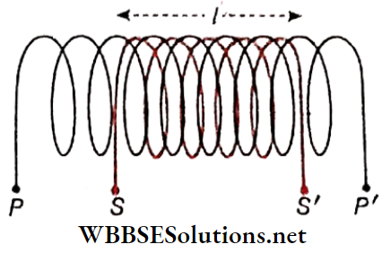
Therefore, the number of turns per unit length of PP’.
⇒ \(n_1=\frac{N_1}{l}\)
If I1 current flows through the primary coil PP’, the magnetic field thus developed inside it,
⇒ \(B_1=\mu_0 n_1 I_1=\frac{\mu_0 N_1}{l} I_1\)
[μ0 = magnetic permeability of vacuum or air]
As the solenoids are closely wound on each other, the magnetic flux linked in each turn of the secondary coil = B1A and hence the magnetic flux linked with N2 turns,
⇒ \(\phi_2=N_2 B_1 A=\frac{\mu_0 N_1 N_2 A}{l} \cdot I_1\)
If the mutual, inductance of the solenoid is M then,
⇒ \(\phi_2=M I_1\)
So, \(M=\frac{\mu_0 N_1 N_2 A}{l}\) → (2)
For any other medium used as the core, M = \(\frac{\mu N_1 N_2 A}{l}\), where mu = magnetic permeability of that medium.
In the present context, self-inductances of the coils are
⇒ \(L_1=\frac{\mu_0 N_1^2 A}{l} \text { and } L_2=\frac{\mu_0 N_2^2 A}{l}\)
So, \(L_1 L_2=\left(\frac{\mu_0 A}{l}\right)^2 N_1^2 N_2^2=\left(\frac{\mu_0 N_1 N_2 A}{l}\right)^2=M^2\)
i.e., \(M=\sqrt{L_1 L_2}\)
Comparing this equation with equation (3). we get, k = 1. This is the maximum value of k.
Energy Density In The Magnetic Field Of A Solenoid:
Length of a solenoid = l, cross-sectional area = A
So, its volume = l A.
If N be the total turns ui the solenoid, the number of turns per unit length of it, \(n=\frac{N}{l}\)
If I current flows through the solenoid, the magnetic field thus develops along its axis,
⇒ \(B=\mu_0 n I=\frac{\mu_0 N I}{l} \quad \text { or, } I=\frac{B l}{\mu_0 N}\)
But, self-inductance of the solenoid,
⇒ \(L=\frac{\mu_0 N^2 A}{l}\)
So, the stored energy in its magnetic field,
⇒ \(U=\frac{1}{2} L I^2=\frac{1}{2} \frac{\mu_0 N^2 A}{l}\left(\frac{B l}{\mu_0 N}\right)^2=\frac{1}{2 \mu_0} B^2 L A\)
So, the energy stored per unit volume,
⇒ \(u=\frac{U}{L A}\)
i,e. \(u=\frac{1}{2 \mu_0} B^2\) → (3)
This u is the energy density in the magnetic field. For any other medium, instead of air or vacuum,
⇒ \(u=\frac{1}{2 \mu} B^2\)
Though equation (3) has been established for the magnetic field inside a solenoid, it is a general equation for any magnetic field because the relation is independent of the geometrical features of the inductor.
To find the energy density at a point in any magnetic field the above equation may be applied. Unit of energy density = J.m3 and its dimension = \(\frac{M L^2 T^{-2}}{L^3}=M L^{-1} T^{-2}\)
Example 1. The mutual inductance between two adjacent coils is 1.5 H. If the current in the primary coil changes from 0 to 20 A in 0.05 s, determine the average emf. induced in the secondary coil. If the number of turns in the secondary coll is 800, what change in flux will be, observed in it?
Solution:
The average value of induced emf,
⇒ \(e=-M \frac{\Delta I}{\Delta t}=-1.5 \times \frac{(20-0)}{0.05} \stackrel{211}{=}-\frac{1.5 \times 20}{0.05}=-600 \mathrm{~V}\)
Hence, the magnitude of the induced emf = 600 V.
Again, from the relation Φ = MI, we get,
change in flux, ΔΦ = M. ΔI = 1.5 x (20 – 0) = 30 Wb
Example 2. When the current in a coil changes from + 2 A to -2 A in 0.05 s, an emf of 8 V is induced in the coil. Determine the self-inductance of the coil
Solution:
We know that, \(e=-L \frac{\Delta I}{\Delta t}\)
Self-inductance of the coil, L = \(L=-\frac{e \Delta t}{\Delta I}=\frac{8 \times 0.05}{-2-(+2)}=0.1 \mathrm{H}\)
Conceptual Questions on Eddy Currents and Their Applications
Example 3. The mutual inductance of two coils is 0.005H, ac in the primary coil, I = I0 sin ωt, where I0 = 10A and ω = 100π rad/s. What is the maximum emf in the secondary coil?
Solution:
ac in the primary coil, I = I0 sin ωt
∴ \(\frac{d I}{d t}=\omega I_0 \cos \omega t\)
So, \(e_2=-M \frac{d I}{d t}\) [here M = mutual inductance]
= -M ωI0 cos ωt
So the maximum emf in the secondary coil
= MωI0 = 0.005 x 100π X 10 = 15.7V
Example 4. If a rate of change of current of 2 A.s-1 induces an emf of 10 mV in a solenoid, what is the self-inductance of the solenoid?
Solution:
∴ \(e=-L \frac{d I}{d \hbar} \quad \text { or, } L=\frac{|e|}{\frac{d I}{d t}}=\frac{10 \times 10^{-3} V}{2 \mathrm{~A} \cdot \mathrm{s}^{-1}}=5 \mathrm{mH}\)
Example 5. The resistance of a coil is 10Ω and its self-inductance is 5H. Find the energy stored when it is connected to a 100V battery.
Solution:
Curreht in circuit, \(I=\frac{V}{R}=\frac{100}{10}=10 \mathrm{~A}\)
Stored energy in the inductor = \(\frac{1}{2} L I^2=\frac{1}{2} \times 5 \times(10)^2=250 \mathrm{~J}\)
Example 6. The self-inductance of an air core solenoid increases from 0.01 mH to 10 mH when an iron core is introduced into it. What is the relative magnetic permeability of iron?
Solution:
Self-inductance is proportional to the permeability of the core. So, we get
⇒ \(\frac{L}{L_0}=\frac{\mu}{\mu_0}=\mu_r \quad \text { or }, \mu_r=\frac{L}{L_0}=\frac{10}{0.01}\)
∴ \(\mu_r=1000\)
Hence relative magnetic permeability of iron is 1000.
Example 7. A small square loop of wire of side y is placed Inside a large square loop of side x (x»y). The loops are coplanar and their centres coincide. Find the mutual inductance of the system.
Solution:
Let I be the current flowing through a square loop of side L.
The magnetic field at the centre of the loop, B = 4B1
[where B1 is the magnetic field at the centre of the loop due to one of its sides]
Now, for the large square loop, L = x
∴ \(B_1=\frac{\mu_0}{4 \pi} \cdot \frac{I}{\frac{x}{2}}\left(\sin 45^{\circ}+\sin 45^{\circ}\right)\) [∵ V distance of the centre from each side of the large loop = \(\frac{x}{2}\)]
⇒ \(=\frac{\mu_0}{2 \pi} \cdot \frac{I}{x}\left(\frac{1}{\sqrt{2}}+\frac{1}{\sqrt{2}}\right)=\frac{\mu_0 I}{\sqrt{2} \pi x}\)
∴ \(B=\frac{4 \mu_0 I}{\sqrt{2} \pi x}=\frac{2 \sqrt{2} \mu_0 I}{\pi x}\)
Now, magnetic flux linked with the small square loop,
Φ =B x area of the small square loop
\(B \times y^2=\frac{2 \sqrt{2} \mu_0 I y^2}{\pi x}\) → (1)
If M be the mutual inductance between the two loops, then
Φ = MI → (2)
From equations (1) and (2), \(M=\frac{2 \sqrt{2} \mu_0 y^2}{\pi x}\)
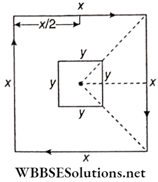
Real-Life Scenarios in Electromagnetic Induction Experiments
Example 8. Cross sectional area, of a solenoid is 10 cm2. Haif of its cross section is filled with iron (μr = 450) and the remaining half with air ( μr = 1 ). Calculate the self-inductance of the solenoid fits length is 2m and the number of turns is 3000.
Solution:
If the α1 part of the cross-section of the solenoid is filled with a substance of relative permeability μr1 and the remaining part of the cross-section α2 with another substance of relative permeability μr2 then self-inductance of the s inside is,
⇒ \(L=\frac{\mu_0 n^2 A}{l}\left(\mu_{r_1} \alpha_1+\mu_{r_2} \alpha_2\right)\)
Here μ0 = 4π x 10-7 H/m; number of Pirns, n = 3000; length of solenoid, l = 2m; area of cross section A = 10cm2 = 0.001m2; α1 = 0.5 and α1 = 0.5.
∴ Self-inductance of the solenoid,
⇒ \(L=\frac{4 \pi \times 10^{-7} \times(3000)^2 \times 0.001}{2}(1 \times 0.5+450 \times 0.5) \mathrm{H}\)
⇒ 2π x 9 x 10-4 x (0.5 + 225) H
= 1.27H (approx.)
Question 1. What is the unit of magnetic induction or magnetic flux density in SI?
Answer: Wb.m-2 or T
Question 2. What is the relation of the magnetic field vector 5 with magnetic induction and magnetic flux density?
Answer: They are the spare physical quantity.
Question 3. Induced emf is direct propohiotfÿ’tti the rate of change with time of magnetic _____ linked with a coil.
Answer: Flux
Question 4. In the case of electromagnetic induction, the _______ always opposes the cause of its generation.
Answer: Current
Question 5. With the help of Fleming’s _______ rule, the direction of induced current in a straight conductor in motion can be determined.
Answer: Right-hand
Question 6. What is the relation between the units: tesla and Weber?
Answer: \(\mathrm{IT}=\frac{1 \mathrm{wb}}{1 \mathrm{~m}^2}\)
Question 7. What is the relation between the units: Weber and Volt?
Answer: 1 Wb = 1 V.1 s
Question 8. Which of the conservation laws would not hold if Lenz’s law was incorrect?
Answer: The law of conservation of energy
Question 9. The self-inductance of a coil is 1H. If 1A current passes through it, what will be the magnetic flux linked with the coil?
Answer: 1 Wb
Question 10. What is the relation between the units: weber and ampere?
Answer: 1 Wb = 1A.1H
Question 11. What is the relation between the units of self-inductance and mutual inductance?
Answer: They have the same unit
Question 12. The self-inductance of an air core inductor increases from 0.01 mH to 10 mH on introducing an iron core into it. What is the relative permeability of the core used?
Answer: 1000
if there is a relative motion between a magnetic field and a conductor, the electromotive force (emf) generated in that conductor is called induced emf.
Faraday’s laws of electromagnetic induction:
Units of magnetic flux:
Units of magnetic induction:
To minimise the loss of energy in the form of heat due to eddy current, the core is not taken as a single piece of conductor but is made of many thin laminas of conductors which are insulated from each other with suitable insulating materials.
⇒ \(\phi=B A \cos \theta=\vec{B} \cdot \vec{A}\)
[where \(\vec{B}\) = magnetic induction, 6 = angle between \(\vec{B}\) and \(\vec{A}\)]
The magnetic flux through a finite surface S,
∴ \(\phi=\int_S \vec{B} \cdot d \vec{A}\)
induced emf, \(e \propto \frac{d \phi}{d t}\). In combination with Lenz’s law and the chosen units of 0, it becomes, \(e=-\frac{d \phi}{d t}\).
∴ \(e=\frac{1}{2} B \omega L^2\)
[where L = length of the conductor, co = steady angular velocity]
Φ ∝ I = 1 or, 0 = LI (L = self-inductance of the coil]
The equation \(e=-\frac{d \phi}{d t} \text { gives, } e=-L \frac{d I}{d t}\)
∴ Wb = H.A, H = n .s
or 1 H = 109 emu of Inductance
Φ ∝ I or, Φ = MI {M = mutual inductance]
A conducting wheel is rotating in a uniform magnetic field with angular velocity co. The length of each spoke is l. If there are n number of spokes in the wheel.
Then total electromotive force between the centre and any point situated on the circumference of the wheel, \(e=\frac{1}{2} B \omega l^2\). Here, the total emf does not depend on the number of spokes.
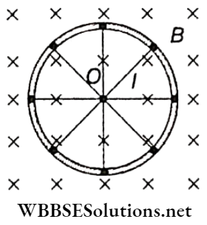
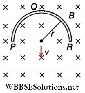
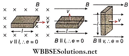
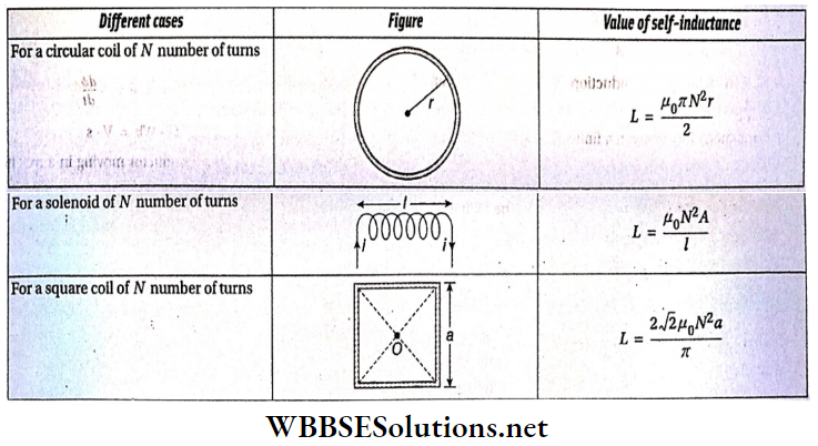
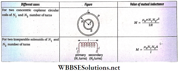
Direction: These questions have statement 1 and statement 2 Of the four choices given below, choose the one that best describes the two statements.
Question 1. Statement 1: Induced emf in a conductor is proportional to the time rate of change of associated magnetic flux.
Statement 2: In the case of electromagnetic induction transfer of energy takes place in a manner energy is conserved.
Answer: 2. Statement 1 is true, Statement 2 Is true) statement 2 is not a correct explanation for statement 1
Question 2. Statement 1: The north pole of a.bar, magnet is moving towards a closed circular coil along its axis. As a result, the direction of induced currently the front face of the coil will be clockwise.
Statement 2: Any incident connected with electromagnetic induction obeys Lenz’s law.
Answer: 4. Statement 1 is false, statement 2 Is true
Question 3. Statement 1: The charge passing through a coil in time At is \(\frac{\Delta \phi}{R}\), where R is the resistance of the coil and ΔΦ is the change in flux linked with the coil in time Δt:
Statement 2: The induced emf in a conductor \(e \propto \frac{d \phi}{d t}\), at \(\frac{d \phi}{d t}\) where is the time rate of change of flux linked with the conductor.
Answer: 1. Statement 1 is true, statement 2 Is true; statement 2 is a correct explanation for statement 1
Question 4. Statement 1: A closed solenoid is placed in an external magnetic field. Both the magnetic field and axis of the solenoid are directed along the z-axis. No electromotive force will be induced if the solenoid is rotated along its axis.
Statement 2: Electromagnetic induction in a conducting coil takes place only when the magnetic flux linked with the coil changes with time.
Answer: 1. Statement 1 is true, statement 2 Is true; statement 2 is a correct explanation for statement 1
Question 5. Statement 1: Self-inductance of a solenoid having 1000 turns is l00 mH if the associated magnetic flux linked with each turn is 10-3 Wb for a current of 1 A passing through the solenoid.
Statement 2: The self-inductance L of a coil is defined as Φ = LI when <p is the magnetic flux linked with the coil for a current I through it.
Answer: 4. Statement 1 is false, statement 2 Is true
Question 6. Statement 1: When two coils are wound on each other, the mutual induction between the coils is maximum.
Statement 2: Mutual induction does not depend on the orientation of the coils.
Answer: 3. Statement 1 is true, statement 2 is false
Question 7. Statement 1: When the number of turns of a coil. doubled, the coefficient of self-inductance of the coil becomes 4 times.
Statement 2: Self-inductance oc (number of turns)2
Answer: 1. Statement 1 is true, statement 2 Is true; statement 2 is a correct explanation for statement 1
Question 1. Some physical quantities are given in column 1 while their units are given in column 2.
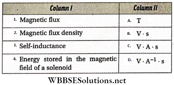
Answer: 1-B, 2-A, 3-D, 4-C.
Question 2. Column 1 gives the value of self-inductance (L) and the current (I) through some coils. Column 2 gives the energy stored in them.
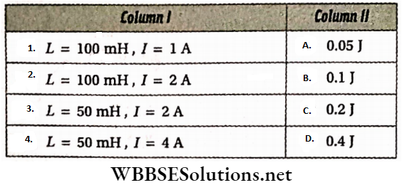
Answer: 1-A, 2-C, 3-B, 4-D
Question 3. Column 1 describes,s some solenoids kept in the air while column 2 gives, their self-inductance. Magnetic permeability of air = 4π x 10-7 H.m-1.
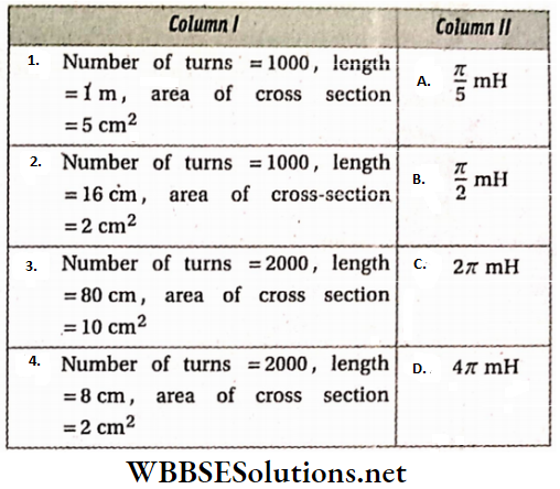
Answer: 1-A, 2-B, 3-C, 4-D
Read The Following Passage Carefully And Answer The Questions At The End Of It.
If the current through a solenoid changes with time electromagnetic induction takes place in the solenoid. This is known as self-induction, In general, for a current I, the induced emf in the coil is \(e=-L \frac{d I}{d t}\).
L is the self-inductance of the solenoid. On the other hand, such a change in the current in a solenoid can produce electromagnetic induction, in another adjacent solenoid. The induced emf in the other solenoid \(e=-M \frac{d I}{d t}\), M is called the mutual inductance of the solenoids.
If L1 and L1 are the self-inductance of the adjacent coils then their mutual inductance \(M=k \sqrt{L_1 L_2}\). If the magnetic flux produced by the current in one coil is linked with the other coil then k = 1.
Question 1. Unit of self-inductance L is Henry (H). Its relation with other known units is
Answer: 3. Ω .s
Question 2. The self-inductance (in H) of a coil when the Induced emf is 5.0μV for a change of 1 mA.s-1 in current through it, is
Answer: 4. 0.05
Question 3. If the induced emf in a coil linked with the coil in question (2) is 20μV, the mutual inductance (in H) of die two coils is
Answer: 2. 0.02
Question 4. Self-inductance (in H) of the coil in question (3) is
Answer: 4. 0.008
Question 5. The negative sign in the expression of induced emf is explained by
Answer: 3. Law of conservation of energy
In this type, the answer to each of the questions Is a single-digit integer ranging from 0 to 9.
Question 1. The current through a coil of self-inductance 500 mH is 4 A. What amount of magnetic energy (in J) is stored in its magnetic field?
Answer: 4
Question 2. A straight conductor of length 50 cm is moving with a velocity of 5 m.s-1 in a magnetic field of strength 2T in a direction perpendicular to the field. What is die emf(in V) induced between the two ends of the conductor?
Answer: 5
Question 3. The magnetic flux Φ (in Wb) linked with a 100H coil changes with time t (in s) according to the relation Φ = 8t2 – 2t + 1. What is the value of induced current (in A) in the coil at t = 2 s?
Answer: 3
Question 4. A straight conductor of length 10 cm Is rotating In a vortical plane with one of Its ends fixed. The angular velocity Is 10 rad.s-1. What is the value of one (In μV ) Induced between the two ends of the conductor If the horizontal component of earth’s magnetic field at the place Is 10-4 T?
Answer: 5
Question 5. A circular wire loop of radius is placed In the xy-plane centred at the origin 0. A square loop of side a (\(a \ll R\)) having two turns is placed with its centre at z = √3R along the axis of the circular wire loop, as shown. The plane of the square loop makes an angle of 45° concerning the z-axis. If the mutual Inductance between the loops is given by \(\frac{\mu_0 a^2}{2^{p / 2} R}\), then what is the value of p?
Answer: 7
Question 6. Find the change in magnetic flux (in Wb )in an inductor of 10H in which the emf induced is 300 V in 10-2 s.
Answer: 3
Question 7. An average induced emf of 0.20 V appears in a coil when the current is changed from 5A in one direction to 5A in the opposite direction in 0.20 s. Find the self-inductance of the coil in mH.
Answer: 4
Each of the following questions comprises two statements. The assertion is expressed by Statement 1 and the reason is expressed by Statement 2.
Each question has four options (1), (2), (3), and (4) as given below, out of which only ONE is correct.
Some questions are preceded, by a supporting paragraph in addition to the statements.

Question 1. Statement 1 The dimensional formula for the product of resistance and conductance is the same as that for the dielectric constant.
Statement 2 Both have the dimension of the time constant.
Answer: 3. Statement 1 is true and Statement 2 is false.
Resistance and conductance are reciprocal to each other, hence their product has no units and no dimensions. The same is true for the dielectric constant (K = ε/ε0), which is a ratio of two permittivities. Hence, Statement 1 is true but Statement 2 is false.
Question 2. Statement 1 SI units are logical and coherent.
Statement 2 This system of units is a rationalized system.
Answer: 2. Statement 1 is true; Statement 2 is true; but Statement 2 is not a correct explanation of Statement 1.
A coherent system of units is based on a system of base units from which all derived units are obtained by multiplication or division without introducing numerical factors. Hence, SI units are logical, coherent, and rationalized.
Question 3. Statement 1 The power of an engine depends on mass, angular speed, torque, and angular momentum, so the formula for power is not derived with the help of the dimensional method.
Statement 2 In mechanics, if a particular physical quantity depends on more than three quantities, we cannot derive the formula of that physical quantity using the dimensional method.
Answer: 1. Statement 1 is true; Statement 2 is true; and Statement 2 is a correct explanation of Statement 1.
In mechanics, the physical quantities have dimensions in terms of M, L, and T only. With dependence on more than three factors, the required relation cannot be derived.
Question 4. Statement 1 The order of accuracy in a measurement depends on the least count of the measuring instrument.
Statement 2 The smaller the least count, the greater the number of significant figures in the measured value.
“physics multiple choice questions “
Answer: 2. Statement 1 is true; Statement 2 is true; but Statement 2 is not a correct explanation of Statement 1.
Both the statements are independently correct.
Question 5. Statement 1 The mass of an object is 24.6 kg. This value contains three significant digits.
Statement 2 The value of the same mass when expressed as 24600 g has five significant digits.
Answer: 3. Statement 1 is true and Statement 2 is false.
The degree of accuracy and hence the number of significant digits of a measurement cannot be increased by changing the unit of a physical quantity.
Question 6. Statement 1 The dimensional method cannot be used to derive the relationship among the work done (W) by a force (F), the displacement (s), and the angle (0) between the directions of \(\vec{F}\) and \(\vec{s}\).
Statement 2 All trigonometric functions are dimensionless.
Answer: 1. Statement 1 is true; Statement 2 is true; and Statement 2 is a correct explanation of Statement 1.
Work done = W = Fs cos θ. Since cos θ is dimensionless, the dependence of W on cos θ cannot be determined.
Question 7. Statement 1 The dimensional formula for RC is the same as that for L/R, where L, C, and R represent, capacitance and resistance respectively.
Statement 2 Both RC and L/R have the dimensions of frequency.
Answer: 3. Statement 1 is true and Statement 2 is false.
The dimensions of both L/R and CR are that of time and not of frequencies, as given in Statement 2.
Question 1. Statement 1 The speedometer of an automobile measures the average speed of the automobile.
Statement 2 The average velocity is equal to the total distance divided by the total time taken.
Answer: 5. Both Statement 1 and Statement 2 are false.
The speedometer measures the instantaneous speed of an automobile.
The average velocity is a vector quantity and is measured by
∴ \(\vec{v}_{\mathrm{av}}=\frac{\text { net displacement }}{\text { time taken }}\)
quiz questions in physics with answers
Question 2. Statement 1 The relative velocity between any two objects moving in opposite directions is equal to the sum of the velocities of the two objects.
Statement 2 Sometimes the relative velocity between two objects is equal to the difference in velocities of the two objects.
Answer: 2. Statement 1 is true; Statement 2 is true; but Statement 2 is not a correct explanation of Statement 1.
When two objects move in opposite directions, the magnitude of relative velocity is equal to the sum of their velocities. When their motion is in the same direction, the relative velocity is equal to the difference of the two velocities.
Question 3. Statement 1 The displacement of a particle may be zero, whereas the distance traveled by it is not zero.
Statement 2 The displacement is the longest distance between the initial and final positions.
Answer: 3. Statement 1 is true and Statement 2 is false.
Read And Learn Also NEET Physics Multiple Choice Question and Answers
When a particle completes a closed loop, its displacement is zero but the distance covered is nonzero! The displacement is measured by the areal distance, or the shortest distance between the two points, not the longest distance.
Question 4. Statement 1 A body can have an acceleration even if its velocity is zero at that instant of time.
Statement 2 A body comes to a momentary rest when it reverses its direction of motion.
Answer: 1. Statement 1 is true; Statement 2 is true; and Statement 2 is a correct explanation of Statement 1.
Consider the motion of an object projected vertically upwards. At the highest point, the object comes to a momentary rest (v = 0) but gravity still acts (so acceleration ≠ 0). This is given as Statement 2.
Question 5. Statement 1 When a body is thrown horizontally or dropped from the same height, it reaches the ground at the same time.
Statement 2 The horizontal velocity has no effect on the vertical direction.
Answer: 1. Statement 1 is true; Statement 2 is true; and Statement 2 is a correct explanation of Statement 1.
The component of the horizontal velocity along the vertical is zero. So, both the bodies reach the ground at the same time.
Question 6. Statement 1 A particle moving in a straight line at a constant speed must have zero acceleration.
Statement 2 A particle moving along a curve at a constant speed may have zero acceleration.
Answer: 3. Statement 1 is true and Statement 2 is false.
A body moving along a curved path changes its direction continuously and represents an accelerated motion.
“physics questions and answers “
Question 7. Statement 1 If the displacement-time graph of the motion of a body is a straight line parallel to the time axis, it follows that the body is at rest.
Statement 2 The time rate of change of displacement measures the instantaneous velocity.
Answer: 1. Statement 1 is true; Statement 2 is true; and Statement 2 is a correct explanation of Statement 1.
The instantaneous velocity is the slope of the displacement-time graph \((\vec{v}=\overrightarrow{d x} / d t)\)
For the zero slope, \(\vec{v}=\overrightarrow{0}\)
Question 8. Statement 1 If the velocity-time graph of a particle in motion is a curve then the particle is either uniformly accelerated or uniformly retarded.
Statement 2 The slope of the velocity-time graph gives the instantaneous acceleration.
Answer: 4. Statement 1 is false and Statement 2 is true.
The slope of the v-t graph gives the instantaneous acceleration. The slope changes continuously if the v-t graph is a curve.
Question 9. Statement 1 In a uniform circular motion, the kinetic energy of a body remains constant.
Statement 2 The momentum of the body does not change with time.
Answer: 3. Statement 1 is true and Statement 2 is false.
The kinetic energy is given by
∴ \(E_{\mathrm{k}}=\frac{1}{2}\left(\frac{\vec{p} \cdot \vec{p}}{m}\right)=\frac{p^2}{2 m}\), which remains constant with time.
But the momentum \((\vec{p})\) is a vector which changes with a change in
direction.
Question 1. Statement 1 Two balls of different masses are projected vertically upwards with the same speed. They will pass through their point of projection simultaneously in the downward direction.
Statement 2 The maximum height and the downward velocity attained at the point of projection are independent of the masses of the balls.
Answer: 1. Statement 1 is true; Statement 2 is true; and Statement 2 is a correct explanation of Statement 1.
A motion under gravity has a constant acceleration \(\vec{g}\) The maximum height and the downward velocity at the point of projection are independent of the mass of the body.
Question 2. Statement 1 Electric current and time both have directions as well as magnitudes. But they are not considered to be vectors.
Statement 2 They do not follow the laws of vector addition.
Answer: 1. Statement 1 is true; Statement 2 is true; and Statement 2 is a correct explanation of Statement 1.
Electric current and time add up scalarly and not like vectors. Hence, they are both scalars and not vectors.
“general science multiple choice questions with answers “
Question 3. Statement 1 When a ball is projected at an angle of 45°, its range is maximum.
Statement 2 For the range to be maximum, the value of sin 20 should be equal to unity.
Answer: 1. Statement 1 is true; Statement 2 is true; and Statement 2 is a correct explanation of Statement 1.
In a projectile motion, the horizontal range is given by R = \(\left(u^2 \sin 2 \theta\right) / g\), and R is maximum when sin 2θ is maximum (= 1), i.e., when θ = 45°.
Question 4. Statement 1 A stone of mass m is tied to a stone of radius R and is whirled in a vertical circle. The minimum speed at the topmost point is \(\sqrt{g R}\).
Statement 2 At the topmost point, the centripetal force is provided partly by the weight (mg) of the stone and partly by the tension in the string.
Answer: 1. Statement 1 is true; Statement 2 is true; and Statement 2 is a correct explanation of Statement 1.
At the topmost point in the vertical circle, the weight and tension taken together provide the required centripetal force. For the minimum speed, tension T = 0. So, \(v_{\min }=\sqrt{g R}\)
Question 5. Statement 1 In javelin throwing, the athlete throws the projectile at an angle slightly more than 45°.
Statement 2 The maximum horizontal range depends on the angle of projection.
Answer: 4. Statement 1 is false and Statement 2 is true.
The maximum range R = \(\left(u^2 \sin 2 \theta\right) / g\) does depend on the angle of projection θ (= 45°).
Question 6. Statement 1 When the velocity of projection of a body is made n times, its time of flight becomes n times.
Statement 2 The range of a projectile does not depend on the initial velocity of the projectile.
Answer: 3. Statement 1 is true and Statement 2 is false.
Time of flight = \(T=\frac{2 u \sin \theta}{g}\)
If \(u^{\prime}=n u, T^{\prime}=\frac{2(n u) \sin \theta}{g}=n T\)
Thus, Statement 1 is true but Statement 2 is false, as the range (R) depends on u and θ both.
Question 7. Statement 1 Generally, the path of a projectile from the earth is parabolic. But it is elliptical for a projectile going up to a very great height.
Statement 2 Up to an ordinary height, a projectile moves under a uniform gravitational force. But for a great height, a projectile moves under a variable force.
Answer: 1. Statement 1 is true; Statement 2 is true; and Statement 2 is a correct explanation of Statement 1.
The path followed by a projectile is parabolic for the heights h«RE, where RE is the radius of the earth. The gravity g remains constant. But for the heights h» RE,g decreases significantly, leading to an elliptical path.
“physics questions and answers pdf “
Question 8. Statement 1 A cyclist leans inwards while taking a turn, whereas a person sitting in a car leans outwards on a curve.
Statement 2 A centripetal acceleration is acting toward the center of the curve.
Answer: 1. Statement 1 is true; Statement 2 is true; and Statement 2 is a correct explanation of Statement 1.
In taking a turn, the cyclist needs a centripetal force towards the center. This force is provided by the frictional force acting between the tires and the ground.
The person sitting in a car is in an accelerated frame and leans outwards due to the pseudo force generated.
Question 9. Statement 1 The position of a particle in the xy-plane is expressed by x = a sin ωt and y = a(1- cos ωt), where a and ω are constants. Then, the particle will have a parabolic motion.
Statement 2 A particle under the influence of two mutually perpendicular velocities does not take a parabolic path.
Answer: 4. Statement 1 is false and Statement 2 is true.
The path followed by the particle will be a circle of radius centered on (0, a), as given below.
⇒ \(\sin \omega t=\frac{x}{a} \text { and } \cos \omega t=1-\frac{y}{a}\)
∴ \(\left(\frac{x}{a}\right)^2+\left(1-\frac{y}{a}\right)^2=1\)
⇒ x2 + (y-a)2 = a2.
So, Statement 1 is false. Under two mutually perpendicular velocities, the path followed will not be a parabola.
Question 10. Statement 1 In a uniform circular motion, the centripetal force is always perpendicular to the velocity vector.
Statement 2 The velocity vector at a point is always along the tangent to the trajectory at the point.
Answer: 1. Statement 1 is true; Statement 2 is true; and Statement 2 is a correct explanation of Statement 1.
In a uniform circular motion, the speed is constant, so KE = constant.
Hence, work done = \(\vec{F} \cdot \vec{s}=0\)
So, \(\vec{F}\) is perpendicular to the velocity vector.
For any trajectory, the velocity vector has its direction tangential to the trajectory.
Question 1. Statement 1 Frictional forces are nonconservative forces.
Statement 2 A potential energy can be associated with a frictional force.
Answer: 3. Statement 1 is true and Statement 2 is false.
Frictional forces dissipate energy and are thus nonconservative. Potential energies can be stored in conservative forces. So, no potential energy can be assigned to a frictional force.
Question 2. Statement 1 The apparent weight of a body in an elevator moving with some downward acceleration is less than the true weight of the body.
Statement 2 A part of the body’s weight is spent in providing the downward acceleration when the body is in the elevator.
Answer: 1. Statement 1 is true; Statement 2 is true; and Statement 2 is a correct explanation of Statement 1.
We feel our weight by the normal reaction \((\mathcal{N})\) offered by the floor.
For a lift accelerating down, mg – \((\mathcal{N})\) = ma.
∴ apparent weight = \((\mathcal{N})\) = mg- ma, which is less than the true weight mg.
Since mg = \((\mathcal{N})\) + ma, part of mg is spent as ma.
Question 3. Statement 1 Two bodies of masses M and m (where M > m) are allowed to fall from the same height. If the air resistance for each is the same then both the bodies will reach the ground simultaneously.
“physics questions and answers pdf “
Statement 2 For the same air resistance, the accelerations of both bodies will not be equal.
Answer: 4. Statement 1 is false and Statement 2 is true.
For the mass M,
∴ \(M g-f=M a_1 \Rightarrow a_1=g-\frac{f}{M}\)
For m, \(a_2=g-\frac{f}{m}\)
Since M>m, a1>a2. Hence, M will reach first and then m. So, Statement 1 is false and Statement 2 is true, since a1 ≠ a2.
Question 4. Statement 1 The use of ball bearings between two moving parts of a machine is a common practice.
Statement 2 The ball bearings reduce rolling friction and provide good stability.
Answer: 1. Statement 1 is true; Statement 2 is true; and Statement 2 is a correct explanation of Statement 1.
Ball bearings reduce rolling friction, and hence using them in machines is a common practice.
Question 5. Statement 1 On a rainy day, it is difficult to drive a car or a bus at a high speed.
Statement 2 The value of the coefficient of friction is lowered on wetting the surface.
Answer: 1. Statement 1 is true; Statement 2 is true; and Statement 2 is a correct explanation of Statement 1.
A wet road reduces friction, so the high-speed movement over such a road may lead to skidding.
Question 6. Statement 1 A horse has to pull a cart harder during the first few steps of its motion.
Statement 2 The first few steps are always difficult.
Answer: 3. Statement 1 is true and Statement 2 is false.
The first few steps are harder, as the horse has to overcome the static friction, which is greater than the kinetic friction.
Question 7. Statement 1 A centripetal force is always required for a motion along a curved path.
Statement 2 On a banked curved track, the vertical component of the normal reaction provides the required centripetal force.
Answer: 3. Statement 1 is true and Statement 2 is false.
A centripetal force is always required for a motion along a curved path. On a banked road, the horizontal component of the normal reaction provides the required centripetal force.
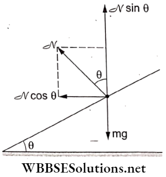
Question 8. Statement 1 A pseudo force is an imaginary force that is recognized only by a noninertial observer to explain the physical situation according to Newton’s laws of motion.
Statement 2 A pseudo force has no physical origin, i.e., it is not caused by the basic interactions in nature. It does not exist in an action-reaction force pair.
Answer: 2. Statement 1 is true; Statement 2 is true; but Statement 2 is not a correct explanation of Statement 1.
In an accelerated (or a noninertial) frame, the observer experiences a pseudo force (= mass of the object x acceleration of the frame with a negative sign = \(-m \vec{a}_{\mathrm{fr}}\)).
However, it is not a field force like gravitational and elastic forces
Question 9. Statement 1 A body subjected to three coplanar concurrent forces may be in equilibrium.
Statement 2 For equilibrium, the vector sum of all the concurrent forces acting at a point should be
Answer: 1. Statement 1 is true; Statement 2 is true; and Statement 2 is a correct explanation of Statement 1.
A body will be in equilibrium if the vector sum of the three concurrent forces acting on it is zero.
Question 10. Statement 1 An animate object can accelerate in the absence of external forces.
Statement 2 Newton’s second law of motion is not applicable to animate objects.
Answer: 4. Statement 1 is false and Statement 2 is true.
When we apply the second law of motion, there is no distinction between whether the object is animate or inanimate. An animate object always requires an external force in order to produce an acceleration.
Question 11. Statement 1 It is difficult to move a cycle along the road with its brakes on.
Statement 2 The degree of sliding friction is always greater than that of rolling friction.
Answer: 1. Statement 1 is true; Statement 2 is true; and Statement 2 is a correct explanation of Statement 1.
With the brakes on, there is no rolling but sliding. Sliding friction is greater than rolling friction, which makes the movement difficult.
Question 12. Statement 1 An impulsive force is large and acts for a short period of time.
Statement 2 A finite change in momentum should be produced by the force.
Answer: 1. Statement 1 is true; Statement 2 is true; and Statement 2 is a correct explanation of Statement 1.
“physics questions and answers pdf “
A large force acting for a short duration is called an impulsive force. According to the impulse-momentum theorem, a change in momentum is produced by the impulse.
Question 13. Statement 1 The driver in a vehicle moving at a constant speed on a straight road is in a noninertial frame of reference.
Statement 2 A reference frame to which Newton’s laws of motion are applicable is noninertial.
Answer: 5. Both Statement 1 and Statement 2 are false.
A motion along a straight line with a uniform velocity has zero acceleration, and such a reference frame is called an inertial frame. A noninertial frame is an accelerated frame. Newton’s second and third laws are valid only when we consider a pseudo-force.
Question 14. Statement 1 It is easier to pull a heavy object than to push it on a level ground.
Statement 2 The magnitude of frictional force depends on the nature of the two surfaces in contact.
Answer: 2. Statement 1 is true; Statement 2 is true; but Statement 2 is not a correct explanation of Statement 1.
While pulling, the component F cos 0 of the pulling force acts against the weight mg, so that the normal reaction is reduced to \(\mathcal{N}\) = mg- F sin 0.
This reduces the kinetic frictional force \(f_{\mathrm{k}}=\mu \mathcal{N}=\mu(m g-F \sin \theta)\)
While pushing, the normal reaction is increased to \(-\mathcal{N}=m g+F \sin \theta\)
Hence, the frictional force becomes \(f_{\mathrm{k}}=\mu(m g+F \sin \theta)\)
Now, more effort is required to overcome the friction.
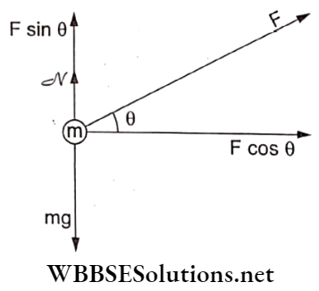
Question 1. Statement 1 In an elastic collision, kinetic energy is conserved.
Statement 2 Energy is always conserved.
Answer: 2. Statement 1 is true; Statement 2 is true; but Statement 2 is not a correct explanation of Statement 1.
In an elastic collision, kinetic energy remains the same before and after the collision. The law of energy conservation is the basic conservation law in nature. Energy may change the form but remains unchanged in total.
Question 2. Statement 1 The work done in a uniform circular motion is zero.
Statement 2 Force is always directed along displacement.
Answer: 3. Statement 1 is true and Statement 2 is false.
In a uniform circular motion, the centripetal force is directed radially inwards, whereas the velocity and displacement vectors are tangential. Hence, work done = W = \(\vec{F} \cdot \vec{s}\) = 0.
Question 3. Statement 1 If the momentum of a body increases by 50%, its kinetic energy will increase by 125%.
Statement 2 Kinetic energy is directly proportional to the square of velocity.
Answer: 1. Statement 1 is true; Statement 2 is true; and Statement 2 is a correct explanation of Statement 1.
⇒ \(\mathrm{KE}=\frac{1}{2} m v^2\)
If m is constant, KE oc v2.
Again, \(\mathrm{KE}=\frac{m^2 v^2}{2 m}=\frac{p^2}{2 m}=E_1\)
With a 50% increase in momentum,
∴ \(\mathrm{KE}=\frac{1}{2 m}\left(p+\frac{p}{2}\right)^2=\frac{9 p^2}{2 m \times 4}=E_2\)
% increase in \(\mathrm{KE}=\frac{\Delta \mathrm{KE}}{\mathrm{KE}} \times 100 \%=\left(\frac{9}{4}-1\right) 100 \%=125 \%\)
| Class 11 Physics | Class 12 Maths | Class 11 Chemistry |
| NEET Foundation | Class 12 Physics | NEET Physics |
Question 4. Statement 1 The total energy is negative for a bound system.
Statement 2 The potential energy of a bound system is negative and more than the kinetic energy.
Answer: 1. Statement 1 is true; Statement 2 is true; and Statement 2 is a correct explanation of Statement 1.
The total energy (KE + PE) of a bound system (like the electron-nucleus system in an atom, the earth-sun system, or an earth-satellite system) is always negative with a negative PE (greater than KE in magnitude). The energy required to detach the component is called the binding energy.
Question 5. Statement 1 A centripetal force does no work.
Statement 2 Force and displacement are mutually perpendicular to each other.
Answer: 1. Statement 1 is true; Statement 2 is true; and Statement 2 is a correct explanation of Statement 1.
Centripetal force and displacement are mutually perpendicular, Hence, the work done is zero.
Question 6. Statement 1 A rigid body can be elastic.
Statement 2 If a force is applied to a rigid body, its dimensions may change.
Answer: 5. Both Statement 1 and Statement 2 are false.
“physics questions and answers pdf “
A rigid body is a solid body in which the deformation is zero or so small that it can be neglected. The separation between any two given points remains constant regardless of the external forces exerted on it.
Question 7. Statement 1 The work done in moving a body over a closed loop is zero for every force in nature.
Statement 2 Work does not depend on the nature of force.
Answer: 4. Statement 1 is false and Statement 2 is true.
The work done over a closed loop is zero only for conservative forces (like gravitational and electrostatic forces). But it is nonzero for nonconservative forces (like friction).
Question 8. Statement 1 The kinetic energy is conserved at every instant during an elastic collision.
Statement 2 No deformation of matter occurs during an elastic collision.
Answer: 4. Statement 1 is false and Statement 2 is true.
A collision is always associated with a deformation for a very short duration. In the process, the KE is converted into PE (during compression) and thereafter back to the same amount of KE during an elastic collision.
Question 9. Statement 1 A quick collision between two bodies is more violent than a slow collision even when the initial and final velocities are identical.
Statement 2 The rate of change of momentum is greater in the first case.
Answer: 1. Statement 1 is true; Statement 2 is true; and Statement 2 is a correct explanation of Statement 1.
According to the impulse-momentum theorem, FΔt = Δp, where F = impact force, Δt = time of impact, and Δp = change in momentum. For the same value of Δp, FΔt = F’Δt’. For a quick collision, Δt is small, so F is large and more violent. For a large Af, F’ is small.
Since F > F’, the rate of change of momentum is
∴ \(\frac{\Delta p}{\Delta t}>\frac{\Delta p}{\Delta t^{\prime}}\)
Question 10. Statement 1 In an elastic collision between two billiard balls, the total kinetic energy is conserved during the short duration of the collision of balls (i.e., as long as they are in contact).
Statement 2 The energy spent against friction still follows the law of conservation of energy.
Answer: 4. Statement 1 is false and Statement 2 is true.
In an elastic collision, there is an exchange between the KE and the elastic PE during the short duration of the impact. So, Statement 1 is false. The energy spent by the frictional force is converted to heat energy. So, energy conservation still follows.
Question 11. Statement 1 A particle collides head-on with another stationary particle such that the first particle comes to rest after the collision. The collision should necessarily be elastic.
Statement 2 In an elastic collision, there is a loss in the momentum of the system of particles.
Answer: 3. Statement 1 is true and Statement 2 is false.
When two particles of equal masses collide elastically, their velocities are mutually interchanged. The linear momentum is always conserved and is valid for all types of collisions.
Question 12. Statement 1 During an elastic collision between two bodies, the relative speed of the approach before the collision is equal to the relative speed of separation after the collision.
Statement 2 In an elastic collision, the linear momentum of the system remains conserved.
Answer: 2. Statement 1 is true; Statement 2 is true; but Statement 2 is not a correct explanation of Statement 1.
The coefficient of restitution is given by
∴ \(e=\frac{\text { relative speed of separation }}{\text { relative speed of approach }}\)
For an elastic collision, e = l. The law of conservation of linear momentum is always true for all types of collisions.
Question 13. Statement 1 In a one-dimensional elastic head-on collision, the total linear momentum remains unchanged before, during, and after the collision.
Statement 2 In a one-dimensional elastic head-on collision, the total kinetic energy remains the same before, during, and after the collision.
Answer: 3. Statement 1 is true and Statement 2 is false.
At the moment the balls A and B collide, A has a larger velocity than that of B, i.e., v1 > v2. But the contact surfaces move through equal distances in equal intervals of time as long as the contact is maintained. During the contact, A and B push each other and the velocities change such that the total momentum still remains unchanged. When some deformation occurs, the total kinetic energy of the system decreases as some energy is stored as elastic compressional potential energy. When the deformation is maximum, the kinetic energy is minimum and the two balls attain equal velocities.
Question 1. Statement 1 If the polar ice melts, days will be longer.
Statement 2 Moment of inertia increases and thus angular velocity decreases.
Answer: 1. Statement 1 is true; Statement 2 is true; and Statement 2 is a correct explanation of Statement 1.
When the polar ice melts, there is a shift of mass from the axis of rotation to away from the axis. This increases the moment of inertia. Since the angular momentum remains constant, ω will decrease and the duration of a day will increase.
Question 2. Statement 1 The earth is slowing down and consequently the moon is coming nearer to it.
Statement 2 The angular momentum of the earth-moon system is always conserved.
Answer: 4. Statement 1 is false and Statement 2 is true.
The earth is not slowing down and the angular momentum of the earth-moon system is always conserved.
Question 3. Statement 1 For a system of particles under a central force field, the angular momentum is conserved.
Statement 2 The torque acting on such a system is zero.
Answer: 1. Statement 1 is true; Statement 2 is true; and Statement 2 is a correct explanation of Statement 1.
Under the central force, \(\vec{F}\) and \(\vec{r}\) are directed along the same line. So, torque = \(\vec{\tau}=\vec{r} \times \vec{F}=\overrightarrow{0}\) . Hence, the angular momentum is conserved.
Question 4. Statement 1 A solid sphere is rolling on a rough horizontal surface. The acceleration of the contact point is zero.
Statement 2 A solid sphere can not roll on a smooth surface.
Answer: 4. Statement 1 is false and Statement 2 is true.
For a pure rolling motion on a horizontal plane, the relative velocity of the point of contact and the tangential acceleration are both zero, but still, there is a radial acceleration directed towards the center. On a smooth surface, the sphere will undergo slipping due to the absence of friction.
Question 5. Statement 1 Moment of inertia is always constant.
Statement 2 Angular momentum is conserved which is why the moment of inertia is conserved.
Answer: 5. Both Statement 1 and Statement 2 are false.
The moment of inertia about a given axis is not constant but depends on the distribution of mass relative to the axis of rotation.
Further, angular momentum is conserved only in the absence of an external torque.
Question 6. Statement 1 The value of the radius of the gyration of a body depends on the axis of rotation.
Statement 2 The radius of gyration of a body is the root-mean-square distance of the particles of the body from the axis of rotation.
Answer: 1. Statement 1 is true; Statement 2 is true; and Statement 2 is a correct explanation of Statement 1.
The radius of gyration (k) of a body depends on the position of the axis of rotation and the distribution of mass around it. Considering the particles of the same mass, we have
∴ \(k=\sqrt{\frac{r_1^2+r_2^2+\ldots+r_n^2}{n}}\) = rms distance.
Question 7. Statement 1 The size and shape of the rigid body remain unaffected under the effect of external forces.
Statement 2 The distance between two particles remains constant in a rigid body.
“physics questions and answers pdf “
Answer: 1. Statement 1 is true; Statement 2 is true; and Statement 2 is a correct explanation of Statement 1.
A rigid body is an ideal concept in which the separation between any of its two particles and the shape and size of the body remain unaffected by external forces and torques.
Question 8. Statement 1 The center of mass of a system does not move under the action of internal forces.
Statement 2 Internal forces are not conservative forces.
Answer: 3. Statement 1 is true and Statement 2 is false.
The acceleration of the center of mass of a system of particles is due only to the external forces acting on the system, and the interval forces have no contributions in accelerating the center of mass. Internal forces always act in pairs (like an action-reaction pair) and they add up to zero for the whole system. Hence, the motion of the center remains unaffected.
Inertial forces are pseudo forces and exist only in noninertial frames to ensure the validity of Newton’s second law.
Question 9. Statement 1 A judo fighter in order to throw his opponent onto the mat tries to bend his opponent initially and then rotate him around his hip.
Statement 2 As the mass of the opponent is brought closer to the fighter’s hip, the force required to throw the opponent is reduced.
Answer: 1. Statement 1 is true; Statement 2 is true; and Statement 2 is a correct explanation of Statement 1.
The rotation of the opponent makes it difficult for the person rotated to resist. By bringing him closer to the hip, the moment of inertia of the opponent is reduced.
Question 10. Statement 1 A wheel moving down a perfectly smooth inclined plane will undergo a slipping (not rolling) motion.
Statement 2 For a perfect rolling motion, the work done against friction is zero.
Answer: 2. Statement 1 is true; Statement 2 is true; but Statement 2 is not a correct explanation of Statement 1.
In the absence of friction on a smooth incline, no frictional torque required for rolling is available. So, the wheel slips.
For a perfectly rolling motion, friction is static and the work done against friction is zero.
Question 11. Statement 1 If the ice cap of the poles melts, the duration of a day will shorten.
Statement 2 Ice will flow towards the equator and increase the moment of inertia of the earth.
Answer: 4. Statement 1 is false and Statement 2 is true.
When the polar ice melts, it spreads over the surface and the moment of inertia increases. In order to conserve the angular momentum, the angular velocity decreases, which increases the duration of a day.
Question 12. Statement 1 The velocity of a body at the bottom of an inclined plane of a given height is more when it slides down the plane compared to when it is rolling down the same plane.
Statement 2 In rolling down, a body acquires kinetic energies of both translation and rotation.
Answer: 1. Statement 1 is true; Statement 2 is true; and Statement 2 is a correct explanation of Statement 1.
During sliding, the total potential energy is converted into kinetic energy. Thus, at the bottom, \(v=\sqrt{2 g h}\). When the body rolls down the plane, the PE is partly converted into KE of translation \(\left(\frac{1}{2} m v^2\right)\) and partly into KE of rotation \(\left(\frac{1}{2} I \omega^2\right)\)
∴ \(v^{\prime}=\sqrt{\frac{2 g h}{1+\frac{k^2}{R^2}}}=\frac{v}{\sqrt{1+\frac{k^2}{R^2}}} \Rightarrow v^{\prime}<v\)
Question 13. Statement 1 There are very small sporadic changes in the period of rotation of the earth.
Statement 2 Shifting of large air masses in the earth’s atmosphere produces a change in the moment of inertia of the earth, causing its period of rotation to change.
Answer: 1. Statement 1 is true; Statement 2 is true; and Statement 2 is a correct explanation of Statement 1.
Shifting of large air masses produces a change in the earth’s moment of inertia, and to keep the angular momentum constant, the period of rotation is changed.
Question 1. Statement 1 An astronaut experiences weightlessness in a space satellite.
Statement 2 When a body falls freely, it does not experience gravity.
Answer: 2. Statement 1 is true; Statement 2 is true; but Statement 2 is not a correct explanation of Statement 1.
A satellite orbiting the Earth is falling (accelerating towards the Earth), but its tangential speed keeps it away from hitting the surface of the Earth.
Objects (or astronauts) in an orbit are said to experience weightlessness. They do have a gravitational force acting on them, but the satellite and all its contents are in free fall, and the absence of any normal reaction leads to the experience of weightlessness.
Question 2. Statement 1 Comets do not obey Kepler’s laws of planetary motion.
Statement 2 Comets have highly elliptical orbits.
Answer: 4. Statement 1 is false and Statement 2 is true.
“physics questions and answers pdf “
Comets go around the sun in a highly elliptical orbit. Like all orbiting bodies, comets also follow Kepler’s second law: the closer they are to the sun, the faster they move.
Question 3. Statement 1 A planet is a heavenly body revolving around the sun.
Statement 2 A star is a luminous body made of gaseous material.
Answer: 2. Statement 1 is true; Statement 2 is true; but Statement 2 is not a correct explanation of Statement 1.
The planets in the solar system orbit the sun under its gravitational force.
Stars are luminous celestial objects containing hydrogen and helium held together by their own gravity.
Question 4. Statement 1 The difference in the values of the acceleration due to gravity at the poles and that at the equator is proportional to the square of the angular speed of the earth.
Statement 2 The value of acceleration due to gravity is minimum at the equator and maximum at the poles.
Answer: 2. Statement 1 is true; Statement 2 is true; but Statement 2 is not a correct explanation of Statement 1.
At the poles, \(g_{\mathrm{P}}=g=\frac{G M_{\mathrm{E}}}{R_{\mathrm{E}}^2}\)
At the equator, \(g_{\mathrm{eq}}=g-R_{\mathrm{E}} \omega^2\)
∴ \(g_{\mathrm{p}}-g_{\mathrm{eq}}=R_{\mathrm{E}} \omega^2 \propto \omega^2\)
Hence, geq is the minimum value of the acceleration due to gravity.
Question 5. Statement 1 The earth without its atmosphere would be inhospitably cold.
Statement 2 All heat would escape the earth in the absence of the atmosphere.
Answer: 1. Statement 1 is true; Statement 2 is true; and Statement 2 is a correct explanation of Statement 1.
The atmosphere protects life on the earth by absorbing the solar UV radiations warming the surface through heat retention and reducing the temperature extremes between day and night The moon has no atmosphere and its temperature in sunlight is around 122 °C. The moon’s surface freezes at -152.7 °C at night; and a similar would be the case with the earth, whose surface would be inhospitably cold without its atmosphere.
Question 6. Statement 1 Water kept in an open vessel will quickly evaporate on the surface of the moon.
Statement 2 The temperature at the surface of the moon is much higher than the boiling point of water.
Answer: 2. Statement 1 is true; Statement 2 is true; but Statement 2 is not a correct explanation of Statement 1.
Due to the negligibly low pressure on the moon, water evaporates quickly. During the daytime, the temperature is very high (above the water’s boiling point) and water will boil.
Question 7. Statement 1 The time period of revolution of a satellite around the planet is directly proportional to the radius of the orbit of the satellite.
Statement 2 Artificial satellites follow Kepler’s laws of planetary motion.
Answer: 4. Statement 1 is false and Statement 2 is true.
Kepler’s laws of planetary motion are followed by the orbital motion of artificial satellites, like all planetary motions. For such a motion, the square of the time of revolution is directly proportional to the cube of the radius of the orbit. Hence, T ∝ R is a false relation.
Question 8. Statement 1 The square of the period of revolution of a planet is proportional to the cube of the semimajor axis of its elliptical orbit.
Statement 2 The sun’s gravitational field is inversely proportional to the square of its distance from the planet.
Answer: 1. Statement 1 is true; Statement 2 is true; and Statement 2 is a correct explanation of Statement 1.
Kepler’s law of periods \(\left(T^2 \propto a^3\right)\) is true. This law is based on Newton’s law of gravitation \(\left(F \propto \frac{1}{r^2}\right)\).
Question 9. Statement 1 If a pendulum falls freely under gravity then its time period becomes infinite.
Statement 2 A freely falling body has an acceleration equal to g.
Answer: 1. Statement 1 is true; Statement 2 is true; and Statement 2 is a correct explanation of Statement 1.
In free fall, there is no normal force or tension, so the bob is in a state of weightlessness, and geff = 0.
Hence, time period = \(T=2 \pi \sqrt{\frac{l}{g_{\text {eff }}}}=\infty\)
A body falling freely under gravity has an acceleration of g.
Question 10. Statement 1 The length of the day is slowly increasing.
Statement 2 The dominant effect causing a slowdown in the rotation of the Earth is the combined gravitational pull of other planets in the solar system.
Answer: 3. Statement 1 is true and Statement 2 is false.
The earth’s rotation is slowing down slightly with time. This is due to the tidal effects the moon has on the Earth’s rotation. This causes a slow increase in the length (duration) of the day. Gravitational pulls are central forces that do not produce any external torques, so angular momenta will remain conserved.
Question 11. Statement 1 A person in a closed cabin falling freely under gravity does not experience gravity.
Statement 2 The inertial mass and the gravitational mass have an equivalence.
Answer: 2. Statement 1 is true; Statement 2 is true; but Statement 2 is not a correct explanation of Statement 1.
We feel our weight by. the normal force exerted by the surface in contact. From the adjoining figure,
⇒ \(F_{\text {net }}=m g-\mathcal{N} \text { but } F_{\text {net }}=m g\)
∴ \(\mathcal{N}=0\)
Hence, it is a state of effective weightlessness.
Mass is always equal to the ratio F/a. So, gravitational and inertial masses are equal.
Question 12. Statement 1 Kepler’s second law can be understood by the principle of conservation of angular momentum.
Statement 2 Kepler’s second law is related to areal velocity, which can further be proved to be based on the principle of conservation of angular momentum as \(\frac{d A}{d t}=\frac{1}{2} r^2 \omega\).
Answer: 1. Statement 1 is true; Statement 2 is true; and Statement 2 is a correct explanation of Statement 1.
Kepler’s second law (areal velocity = constant) leads to the principle of conservation of angular momentum.
Question 13. Statement 1 The angular speed of a planet orbiting around the sun increases when it is closer to the sun.
Statement 2 The total angular momentum of the system remains constant.
Answer: 1. Statement 1 is true; Statement 2 is true; and Statement 2 is a correct explanation of Statement 1.
From Kepler’s second law,
∴ \(\frac{1}{2} r^2-\frac{d \theta}{d t}=\cos x\),
Where \(\frac{d \theta}{d t}=\omega\) is the angular velocity.
When the planet is closer to the sun, r decreases, so ω increases.
This is linked with the principle of conservation of angular momentum.
Question 14. Statement 1 The total energy is conserved in moving a satellite to a higher orbit.
Statement 2 The sum of the changes in KE and PE is the same in magnitudes but opposite in nature.
Answer: 3. Statement 1 is true and Statement 2 is false.
The total mechanical energy (= KE + PE) of an artificial satellite orbiting the earth is \(E=-\frac{G M_E m}{2\left(R_E+h\right)}\), where ME is the mass of the earth and RE is the radius of the orbit. When raised to a higher orbit, h increases and E also increases (i.e., becomes less negative). The difference in energy is given by the system, so the energy is conserved.
Question 15. Statement 1 At the poles, the values of the acceleration due to gravity (g) are greater than that at the equator.
Statement 2 The earth rotates on its axis in addition to its revolution around the sun.
Answer: 1. Statement 1 is true; Statement 2 is true; and Statement 2 is a correct explanation of Statement 1.
At the equator, \(g_{\mathrm{eq}}=g-\omega^2 R_{\mathrm{E}}\) nd at the poles, gp = g. Thus, gp > geq. This change is due to the rotation (spin) of the earth about its own axis as well as to the unequal distances of the poles and the equator from the earth’s center.
Question 16. Statement 1 A geostationary satellite must be located in the equatorial plane at some point vertically above the equator.
Statement 2 The only external force acting on an artificial satellite is directed toward the centre of the earth.
Answer: 1. Statement 1 is true; Statement 2 is true; and Statement 2 is a correct explanation of Statement 1.
A geostationary satellite is located in a circular orbit at a height of 35786 km above the Earth’s equator in the equatorial plane so that it appears motionless at a fixed position in the sky to an observer on the Earth.
For the circular motion of the satellite, the gravitational attraction by the earth provides the required centripetal force.
Question 17. Statement 1 The gravitational potential energy of a solid sphere is negative.
Statement 2 Two bodies attract each other
Answer: 1. Statement 1 is true; Statement 2 is true; and Statement 2 is a correct explanation of Statement 1.
In an attractive field, the potential energy is always negative. Gravitation is a conservative attractive force. So, a sphere requires some energy to pull apart all its fragments, so that the PE increases from the negative value to zero.
Question 1. Statement 1 The periodic time of a hard spring is less as compared to that of a soft spring.
Statement 2 The periodic time depends on the spring constant, which is larger for hard springs.
Answer: 1. Statement 1 is true; Statement 2 is true; and Statement 2 is a correct explanation of Statement 1.
The time period of a spring-block system is given by
∴ \(T=2 \pi \sqrt{\frac{m}{k}}\)
where khard>ksoft.
Question 2. Statement 1 The time period of a pendulum on a satellite orbiting the earth is infinity.
Statement 2 The time period of a pendulum is inversely proportional to √g.
Answer: 1. Statement 1 is true; Statement 2 is true; and Statement 2 is a correct explanation of Statement 1.
In a satellite orbiting the Earth, any object is in a state of weightlessness.
So, \(g_{\mathrm{eff}}=0 \text { and } T=2 \pi \sqrt{\frac{l}{g_{\mathrm{eff}}}}=\infty\)
Question 3. Statement 1 Soldiers are asked to break steps while crossing the bridge.
Statement 2 The frequency of marching may be equal to the natural frequency of the bridge and may lead to resonance which can break the bridge.
Answer: 1. Statement 1 is true; Statement 2 is true; and Statement 2 is a correct explanation of Statement 1.
Statement 1 is true because the marching soldiers are asked not to be in steps so as to avoid any resonance. At resonance, the amplitude of oscillations becomes very large. This may damage the. bridge.
Question 4. Statement 1 In an SHM, the kinetic and potential energies become equal when the displacement is (1/√2) times the amplitude.
Statement 2 In an SHM, the kinetic energy is zero when the potential energy is maximum.
Answer: 2. Statement 1 is true; Statement 2 is true; but Statement 2 is not a correct explanation of Statement 1.
In an SHM, \(\mathrm{KE}=\frac{1}{2} m \omega^2\left(A^2-x^2\right) \text { and } \mathrm{PE}=\frac{1}{2} m \omega^2 x\)
Both the energies are equal at \(x= \pm \frac{A}{\sqrt{2}}\). When the KE is zero, the PE is maximum, so that their sum remains conserved.
Question 5. Statement 1 In an SHM, the motion is to and fro as well as periodic.
Statement 2 The velocity of the particle is \(v=\omega \sqrt{A^2-x^2}\), where x is the displacement and A is the amplitude.
Answer: 2. Statement 1 is true; Statement 2 is true; but Statement 2 is not a correct explanation of Statement 1.
An SHM is a periodic motion about the mean position with the velocity \(v=A \omega \cos \omega t=\omega \sqrt{A^2-x^2}\).
Question 6. Statement 1 The resonance is a special case of forced vibrations in which the natural frequency of vibrations of the body is the same as the impressed frequency and the amplitude of the forced vibrations is maximum.
Statement 2 The amplitude of the forced vibrations of a body increases with an increase in the frequency of an externally impressed periodic force.
Answer: 3. Statement 1 is true and Statement 2 is false.
In a forced SHM, resonance is a special case when the natural frequency of the oscillator is the same as that of the external periodic force. Before resonance, the amplitude increases with an increase in frequency; and beyond resonance, the amplitude decreases with an increase in frequency.
Question 7. Statement 1 The graph of the potential energy and kinetic energy of a particle executing an SHM with respect to its position (x) is a parabola.
Statement 2 The potential energy and kinetic energy do not vary linearly with the position.
Answer: 2. Statement 1 is true; Statement 2 is true; but Statement 2 is not a correct explanation of Statement 1.
The graphs showing the variations of the KE and PE versus the position (x) is a parabola. The KE and PE vary as x2. The curve is nonlinear.
Question 8. Statement 1 Let the bob of a simple pendulum be a ball full of water. If a fine hole is made in the bottom of the ball, the time period first increases and then decreases.
Statement 2 As water flows out of the ball, its weight decreases.
Answer: 3. Statement 1 is true and Statement 2 is false.
When water gets drained out of the shell, the center of mass is lowered, thus increasing the length of the pendulum. Consequently, the time period increases. When the shell is more than half-empty, the center of mass again rises up with a decrease in the length and a decrease in the time period of the pendulum.
The time period \(T=2 \pi \sqrt{\frac{l}{g}}\) is independent of the weight of the bob.
Question 9. Statement 1 The amplitude of an oscillating pendulum decreases gradually with time.
Statement 2 The frequency of oscillations of the pendulum decreases with time.
Answer: 1. Statement 1 is true; Statement 2 is true; and Statement 2 is a correct explanation of Statement 1.
In the presence of damping (air friction), the displacement amplitude decreases exponentially with time. The frequency of oscillations also decreases with time, so that the oscillations become slow.
Question 1. Statement 1 Stress is the internal force per unit area of a body.
Statement 2 Rubber is more elastic than steel.
Answer: 3. Statement 1 is true and Statement 2 is false.
Stress is developed in a body due to the internal forces per unit area. Steel is more elastic than rubber.
Question 2. Statement 1 A hollow shaft is found to be stronger than a solid shaft made of the same material.
Statement 2 The torque required to produce a given twist in a hollow cylinder is greater than that required to twist a solid cylinder of the same material and of the same dimensions.
Answer: 1. Statement 1 is true; Statement 2 is true; and Statement 2 is a correct explanation of Statement 1.
If two cylinders of the same length, the same mass, and the same material are made such that one is solid while the other is hollow then it can be shown that the twisting couple per unit twist for a hollow cylinder is greater than that for a solid cylinder. Hence, hollow shafts are stronger.
Question 3. Statement 1 Lead is more elastic than rubber.
Statement 2 If the same load is attached to lead and rubber wires of the same cross-sectional area, the strain in the lead wire is very much less than that in the rubber wire.
Answer: 1. Statement 1 is true; Statement 2 is true; and Statement 2 is a correct explanation of Statement 1.
The material for which the stress at the elastic limit is more is said to be more elastic. This corresponds to Statement 2.
Question 4. Statement 1 A hydrogen-filled balloon stops rising after it has attained a certain height in the sky.
Statement 2 The atmospheric pressure decreases with height and becomes zero when the maximum height is attained.
Answer: 3. Statement 1 is true and Statement 2 is false.
Hydrogen is lighter than air, so it rises up due to a buoyant force. It stops rising further after some height. In the upper atmosphere, the pressure is low, so the balloon expands, and its buoyancy increases but not the pull of gravity. It stops in equilibrium. At the maximum height, the atmospheric pressure is not zero.
Question 5. Statement 1 The specific gravity of a liquid is a dimensionless quantity.
Statement 2 It is the ratio of the density of the fluid to the density of water.
Answer: 1. Statement 1 is true; Statement 2 is true; and Statement 2 is a correct explanation of Statement 1.
The specific gravity of a substance is its density relative to water. So, it is dimensionless.
Question 6. Statement 1 For a Reynolds number Re > 2000, the nature of the flow of a fluid is turbulent.
Statement 2 Inertial forces are dominant compared to the viscous forces at such a high Reynolds number.
Answer: 1. Statement 1 is true; Statement 2 is true; and Statement 2 is a correct explanation of Statement 1.
The Reynolds number is defined as the ratio
∴ \(R e=\frac{\text { inertial forces }}{\text { viscous forces }}\)
When the ratio exceeds 2000, the nature of flow becomes turbulent due to the dominance of inertial forces over viscous forces.
Question 7. Statement 1 Machine parts get jammed in winter.
Statement 2 The viscosity of a lubricant used in machine parts increases at low temperatures.
Answer: 1. Statement 1 is true; Statement 2 is true; and Statement 2 is a correct explanation of Statement 1.
In winter, when the temperature considerably drops, the viscosity of lubricating oil increases, so the oil does not reach the machine parts easily, leading to a jam inside.
Question 8. Statement 1 A thin stainless-steel needle can lay floating on a still water surface.
Statement 2 Any object floats when the buoyant force balances the weight of the body.
Answer: 2. Statement 1 is true; Statement 2 is true; but Statement 2 is not a correct explanation of Statement 1.
A steel needle presses the water surface and experiences forces due to the surface tension to keep floating. For equilibrium, the weight and the buoyant force must balance each other.
Question 9. Statement 1 The shape of an automobile is so designed that its front resembles the streamlined pattern of the fluid through which it moves.
Statement 2 The resistance offered by the fluid on streamlined objects is maximum.
Answer: 3. Statement 1 is true and Statement 2 is false.
The automobiles are designed to have a streamlined shape in the front part. This reduces the aerodynamic drag so as to minimize the resistance offered by the fluid.
Question 10. Statement 1 Turbulence is always dissipative.
Statement 2 A high Reynolds number promotes turbulence.
Answer: 2. Statement 1 is true; Statement 2 is true; but Statement 2 is not a correct explanation of Statement 1.
In a turbulent flow, an energy dissipation occurs. During the turbulent flow, the Reynolds number is high.
Question 11. Statement 1 A needle placed carefully on the surface of still water may float, whereas the ball of the same material will always sink.
Statement 2 The buoyancy of an object depends both on the material and shape of the object.
Answer: 3. Statement 1 is true and Statement 2 is false.
A needle floats on a water surface due to the force of surface tension balancing the weight. A solid sinks because the buoyant force is not sufficient to balance the weight. Buoyancy depends only on the shape.
Question 12. Statement 1 The smaller drops of a liquid resist deforming forces better than the larger drops.
Statement 2 The excess pressure inside a drop is directly proportional to its surface area.
Answer: 3. Statement 1 is true and Statement 2 is false.
The excess pressure \(\left(\Delta p=\frac{2 T}{R}\right)\) inside a smaller drop is larger, hence it offers more resistive force for deformation than a larger drop. The excess pressure varies as 1 /R and it does not depend on the surface area.
Question 13. Statement 1 The surface energy of an oil drop is the same whether placed on a glass or a water surface.
Statement 2 The surface energy is dependent only on the properties of the oil.
Answer: 5. Both Statement 1 and Statement 2 are false.
The surface tension is a molecular phenomenon and depends on cohesive and adhesive forces. So, the surface energy for an oil-glass pair is different than that for an oil-water pair. It depends on both the surfaces in contact.
Question 14. Statement 1 When the height of a capillary tube is less than the liquid rise in the capillary tube, the liquid does not overflow.
Statement 2 The product of the radius of a concave meniscus and the height of liquid in a capillary tube always remains constant.
Answer: 1. Statement 1 is true; Statement 2 is true; and Statement 2 is a correct explanation of Statement 1.
When the length of the capillary tube is insufficient, the liquid rises to the top, and the radius of curvature of the concave meniscus changes to ensure that hR remains constant.
Each of the following questions comprises two statements. The assertion is expressed by Statement 1 and the reason is expressed by Statement 2.
Each question has four options (1), (2), (3), and (4) as given below, out of which only ONE is correct.
Some questions are preceded, by a supporting paragraph in addition to the statements.
Question 1. Statement 1 A charged particle free to move in an electric field always moves along the electric field lines.
Statement 2 The electric field lines diverge from a positive charge and converge to a negative charge.
Answer: 4. Statement 1 is false and Statement 2 is true.
A charged particle when released from rest in an electrostatic field always travels along the field. But when its initial velocity makes some angle 0 with the field direction, it follows a parabolic path. Electric field lines diverge from a positive charge.

Question 2. Statement 1 If a conductor is given charge then no excess inner charge appears;
Statement 2 The electric field inside a conductor is always zero.
Answer: 1. Statement 1 is true; Statement 2 is true; and Statement 2 is a correct explanation of Statement 1.
The charge given to a conductor totally remains on the outer surface and no part of it appears on the inner surface. The electric field inside a conductor is zero as a consequence of Gauss’s theorem and the absence of an inner charge.
Question 3. Statement 1 An electrostatic field line never forms a closed loop.
Statement 2 An electrostatic field is a conservative force field.
Answer: 1. Statement 1 is true; Statement 2 is true; and Statement 2 is a correct explanation of Statement 1.
Electrostatic field lines do not form a closed loop. In a dipole, they start at the positive charge and terminate at the negative charge. This corresponds to the conservative nature of an electrostatic field for which the work done for a closed path is zero.
Question 4. Statement 1 Gauss’s law cannot be used to calculate the electric field near an electric dipole.
Read And Learn Also NEET Physics Multiple Choice Question and Answers
Statement 2 An electric dipole does not have symmetrical charge distribution.
Answer: 1. Statement 1 is true; Statement 2 is true; and Statement 2 is a correct explanation of Statement 1.
Gauss’s law is applicable when the charge distribution is cylindrical, spherical, or planar. It cannot be applied for an asymmetric charge distribution like that of an electric dipole.
Question 5. Statement 1 The Nuclear force is a dominating force in nature.
Statement 2 The Coulomb force is weaker than the gravitational force.
Answer: 3. Statement 1 is true and Statement 2 is false.
The nuclear forces are the strongest in nature, whereas the Coulomb force is much stronger than the gravitational force.
Question 6. Statement 1 On going away from a point charge or a small electric dipole, the electric field decreases at the same rate in both cases.
Statement 2 An electric field is inversely proportional to the square of the distance from the charge and the cube of the distance from the electric dipole.
Answer: 4. Statement 1 is false and Statement 2 is true.
The electric field due to a dipole \(\propto \frac{1}{r^3}\), and that due to a monopole \(\propto \frac{1}{r^2}\).
∴ \(\left(\frac{d E}{d r}\right)_{\text {dipole }} \propto \frac{1}{r^4} \text { and }\left(\frac{d E}{d r}\right)_{\text {monopole }} \propto \frac{1}{r^3}\)
Question 7. Statement 1 A Gaussian surface is considered carefully.
Statement 2 The point where the electric field is to be calculated should be within the surface.
Answer: 5. Both Statement 1 and Statement 2 are false.
A Gaussian surface is symmetrical about the given charge distribution, and the point where the field is to be found is outside the Gaussian surface.
Question 8. Statement 1 In the cavity within a conductor, the electric field is zero.
Statement 2 Charges with a conductor always reside only at its outer surface.
Answer: 1. Statement 1 is true; Statement 2 is true; and Statement 2 is a correct explanation of Statement 1.
The electric field in the cavity of a charged conductor is always zero because no charge exists on the inner surface. Both of these facts are consequences of Gauss’s theorem.
Question 9. Statement 1 Gauss’s law shows a diversion when the inverse square law is not obeyed.
Statement 2 Gauss’s law is a consequence of the conservation of charges.
Answer: 2. Statement 1 is true; Statement 2 is true; but Statement 2 is not a correct explanation of Statement 1.
Gauss’s law is a consequence of the inverse-square law. Charge cannot be created nor be destroyed, it always remains conserved.
| Class 11 Physics | Class 12 Maths | Class 11 Chemistry |
| NEET Foundation | Class 12 Physics | NEET Physics |
Question 10. Statement 1 The acceleration of a charged particle in a uniform electric field does not depend on the velocity of the charged particle.
Statement 2 Charge is an invariant quantity, which means that the amount of charge with a particle does not depend on the frame of reference.
Answer: 2. Statement 1 is true; Statement 2 is true; but Statement 2 is not a correct explanation of Statement 1.
Force = F = qE; acceleration = \(a=\frac{F}{m}=\frac{q E}{m}\)
Since q, E, and m are constants, the acceleration a is also a constant and independent of the velocity of the charged particle. Charge is always invariant.
Question 11. Statement 1 If an electron and a proton possessing equal KEs enter an electric field in a particular direction, the path of the electron will be more curved than that of the proton.
Statement 2 An electron describes a larger curve due to its small mass.
Answer: 5. Both Statement 1 and Statement 2 are false.
When a charged particle is projected at some angle θ (≠ 0° or π), it follows a parabolic path, for which the curvature varies from point to point.
At a given point, \(F=q E=\frac{m v^2}{r}=\frac{2 \mathrm{KE}}{r}\)
An electron and a proton have the same KE and the same charge, so the radius of the curvature r will be the same and the path followed will be the same.
Question 12. Statement 1 Electrons move away from a region of lower potential to a region of higher potential.
Statement 2 An electron has a negative charge.
Answer: 1. Statement 1 is true; Statement 2 is true; and Statement 2 is a correct explanation of Statement 1.
Electrons are negatively charged particles that move against the direction of the electric field. An electric field is directed from a higher potential to a lower potential.
Question 13. Statement 1 The electrical potential of the earth is taken as zero.
Statement 2 No electric field exists on the earth’s surface.
Answer: 3. Statement 1 is true and Statement 2 is false.
The earth is a very large conducting body where the addition or subtraction of charges is insignificant. Hence, its potential is taken to be zero. Near the surface of the earth, the magnitude of the electric field is around 100 V m-1.
Question 14. Statement 1 Electric field lines are perpendicular to a conducting surface.
Statement 2 Electric field lines are perpendicular to an equipotential surface.
Answer: 1. Statement 1 is true; Statement 2 is true; and Statement 2 is a correct explanation of Statement 1.
A conducting surface is equipotential, on which the electrical field is directed perpendicular to its surface.
Question 15. Statement 1 Two adjacent spherical conductors carrying the same amount of positive charge have a potential difference between them.
Statement 2 The potential to which a conductor is raised depends on the charge.
Answer: 2. Statement 1 is true; Statement 2 is true; but Statement 2 is not a correct explanation of Statement 1.
The potential of a spherical conductor of radius R is \(V=\frac{1}{4 \pi \varepsilon_0} \frac{Q}{R}\).
If the charge is the same and the radii of the spheres are unequal then their potentials will be different. The potential V depends on both the charge Q and the radius R.
Question 16. Statement 1 An electric field is preferred to a magnetic field for deflecting the electron beam in a television picture tube.
Statement 2 An electric field requires a low voltage.
Answer: 4. Statement 1 is false and Statement 2 is true.
In television picture tubes, a magnetic field is preferred to an electric field for deflecting the electron beam.
The electric field \(E=\frac{V}{d}\) requires a high voltage to produce the required field.
Question 17. Statement 1 If a dielectric is placed in an external field then the field inside the dielectric will be less than the field outside.
Statement 2 The electric field will induce a dipole moment opposite to the field direction.
Answer: 3. Statement 1 is true and Statement 2 is false.
Dielectric polarization produces a field in a direction opposite to the externally applied field.
Polarization produces dipoles whose moments (-ve to +ve) are directed along the externally applied field.
Question 18. Statement 1 The electrostatic potential energy of a spherical shell with a uniformly distributed negative charge is positive.
Statement 2 Two similar charges repel each other.
Answer: 1. Statement 1 is true; Statement 2 is true; and Statement 2 is a correct explanation of Statement 1.
Potential energy = work done
∴ \(\int d W=\int V d q=\int_0^{-Q_1} \frac{1}{4 \pi \varepsilon_0 R}(-q)(-d q)=\frac{Q^2}{8 \pi \varepsilon_0 R}=\frac{( \pm Q)^2}{8 \pi \varepsilon_0 R}\)
This is positive for both positive and negative charges. Potential energy is positive for a repulsive field (repulsive force between two like charges).
Question 19. Statement 1 When an uncharged parallel-plate capacitor is charged by connecting it to a cell, the heat produced in the circuit is equal to the energy stored in the capacitor.
Statement 2 The charge on a parallel-plate capacitor means equal and opposite charges on its inner faces.
Answer: 2. Statement 1 is true; Statement 2 is true; but Statement 2 is not a correct explanation of Statement 1.
Total energy delivered by the cell = Qε .
Energy stored in the capacitor = \(\frac{Q^2}{2 C}=\frac{Q \varepsilon}{2}\).
Heat developed = \(\mathrm{Q} \varepsilon-\frac{\mathrm{Q} \varepsilon}{2}=\frac{\mathrm{Q} \varepsilon}{2}\).
A charged capacitor has equal and opposite charges, which produce an electrostatic field between the plates.
Question 20. Statement 1 It is possible for a charged particle to move in a circular path around a uniformly charged, long, straight conductor.
Statement 2 The electrostatic force on a moving charged particle is directed toward the conductor.
Answer: 1. Statement 1 is true; Statement 2 is true; and Statement 2 is a correct explanation of Statement 1.
The electrostatic field due to a long, straight-charged conductor is radial, which can provide a centripetal force to the charged particle moving along the circle/with the axis as the conductor.
Each of the following questions comprises two statements. The assertion is expressed by Statement 1 and the reason is expressed by Statement 2.
Each question has four options (1), (2), (3), and (4) as given below, out of which only ONE is correct.
Some questions are preceded, by a supporting paragraph in addition to the statements.
Question 1. Statement 1 A photon has no rest mass, yet it carries a definite momentum.
Statement 2 The momentum of a photon is due to its energy and henceit has an equivalent mass.
Answer: 1. Statement 1 is true; Statement 2 is true; and Statement 2 is a correct explanation of Statement 1.
A particle that travels at the speed of light (a photon) has a zero rest mass but has an energy of E =hf and momentum of \(p=\frac{h}{\lambda}=\frac{E}{c}\)
Question 2. Statement 1 The energy (E) and momentum (p) of a photon are related by \(p=\frac{E}{c}\)
Statement 2 A photon behaves like a particle.
Answer: 1. Statement 1 is true; Statement 2 is true; and Statement 2 is a correct explanation of Statement 1.
The energy of a photon of frequency f is E = hf and its momentum is \(p=\frac{h}{\lambda}=\frac{E}{c}\).
A photon has a particle nature to describe the photoelectric effect.

Question 3. Statement 1 When light of a certain wavelength falls on a metal surface, it ejects electrons.
Statement 2 Light has a wave nature.
Answer: 2. Statement 1 is true; Statement 2 is true; but Statement 2 is not a correct explanation of Statement 1.
When a light of a wavelength less than the threshold wavelength strikes a photosensitive surface, photoelectrons are ejected. This is explained by the photon (particle) theory. But light has a dual (both particle and wave) nature.
Question 4. Statement 1 On increasing the frequency of light, a larger number of photoelectrons are emitted.
Statement 2 The maximum KE of electrons emitted is directly proportional to the intensity of the incident light.
Answer: 5. Both Statement 1 and Statement 2 are false.
The number of photoelectrons ejected is directly proportional to the intensity of the incident light and not to the frequency of the incident light. The maximum KE of the emitted photoelectrons depends on the frequency and not on the intensity of the incident radiation.
Read And Learn Also NEET Physics Multiple Choice Question and Answers
Question 5. Statement 1 There is a physical significance of matter waves.
Statement 2 Both interference and diffraction are displayed by matter waves.
Answer: 1. Statement 1 is true; Statement 2 is true; and Statement 2 is a correct explanation of Statement 1.
Particles exhibit a wave nature as well. They can be diffracted (as in the Davisson-Germer experiment) and the phenomenon of matter-wave interference lies at the heart of quantum physics.
Question 6. Statement 1 The relative velocity of two photons travelling in opposite directions is the velocity of light.
Statement 2 The rest mass of a photon is zero.
Answer: 2. Statement 1 is true; Statement 2 is true; but Statement 2 is not a correct explanation of Statement 1.
According to the theory of relativity, speed cannot exceed that of light in a vacuum (c = 3 x10² m s-1). Photons travel at the speed of light, and their relative velocity when moving apart will be c. The rest mass of a particle traveling at the speed of light is zero. This follows from the equation
∴ \(m=\frac{m_0}{\sqrt{1-\frac{v^2}{c^2}}}\)
physics multiple choice questions
Question 7. Statement 1 An electron microscope is based on the de Broglie hypothesis.
Statement 2 A beam of electrons behaves as a wave that is converged by electric and magnetic lenses.
Answer: 1. Statement 1 is true; Statement 2 is true; and Statement 2 is a correct explanation of Statement 1.
In an electron microscope, a beam of accelerated electrons is used. Its de Broglie wavelength,
∴ \(\lambda=\frac{h}{p}=\frac{h}{\sqrt{2 m e V}}\),
can be around 105 times shorter than that of the visible light (photons). Electric and magnetic fields are used to converge or diverge the electron beam. These fields are analogous to the glass lenses of an optical microscope.
Question 8. Statement 1 The de Broglie equation has significance for microscopic or submicroscopic particles.
Statement 2 The de Broglie wavelength is inversely proportional to the mass of the objectifies velocity is constant.
Answer: 1. Statement 1 is true; Statement 2 is true; and Statement 2 is a correct explanation of Statement 1.
The de Broglie wavelength \(\left(\lambda=\frac{h}{m v}\right)\) has an appreciable value for a particle with a small mass like that of a subatomic particle.
Question 9. Statement 1 The second postulate of the special theory of relativity refers to the velocity of light in a vacuum.
Statement 2 A Cerenkov radiation results when particles move through a transparent medium at a speed greater than that of light in that medium. It does not violate the second postulate of the special theory.
Answer: 2. Statement 1 is true; Statement 2 is true; but Statement 2 is not a correct explanation of Statement 1.
Cerenkov radiation occurs when some particles move through a transparent medium at a speed more than the speed of light in the medium.
Still, the particle’s speed is less than the speed of light in a vacuum. So, the second postulate of special relativity is not violated.
Question 10. Statement 1 Stopping potential depends upon the frequency of the incident light but is independent of the intensity of light.
Statement 2 The maximum kinetic energy of photoelectrons is proportional to the stopping potential.
Answer: 1. Statement 1 is true; Statement 2 is true; and Statement 2 is a correct explanation of Statement 1.
According to Einstein’s equation of photoelectric effect, \(h v=\phi_0+\mathrm{KE}_{\max } \text {, where } \mathrm{KE}_{\max }=e V_{\mathrm{st}}\).
Thus, the stopping potential Vst depends upon v, the frequency of the incident light. Further, KEmax is proportional to Vst.
Question 11. Statement 1 The photoelectric effect demonstrates the wave nature of light.
Statement 2 The number of photoelectrons is proportional to the frequency of light.
Answer: 5. Both Statement 1 and Statement 2 are false.
The photoelectric effect corresponds to the particle nature (photon) of light, not its wave nature.
The photoelectric current is proportional to the intensity of light and not to the frequency of light.
“quiz questions in physics with answers “
Question 12. Statement 1 The maximum kinetic energy of the emitted photoelectrons changes only, with a change in the frequency of the incident radiation.
Statement 2 The kinetic energy of the emitted photoelectrons depends on the intensity of the incident light.
Answer: 3. Statement 1 is true and Statement 2 is false.
From the equation, hv = Φ0 + KEmax, the work function (Φ0) is constant for a metal.
KEmax changes only with a change in the frequency (v) of light.
The intensity of the incident light can change only the photoelectric current and not the maximum kinetic energy of the emitted electrons.
Question 13. Statement 1 The photoelectrons produced by a monochromatic light beam incident on a metal surface have a spread of their kinetic energies.
Statement 2 The work function of the metal varies as a function of the depth from the surface.
Answer: 3. Statement 1 is true and Statement 2 is false.
The spread of kinetic energy of the emitted photoelectrons is due to the collisions of free electrons before emissions. The work function (Φ0) is constant for a metal.
Question 1. Statement 1 The total energy of an electron in a hydrogen atom is negative.
Statement 2 It is bound to the nucleus.
Answer: 1. Statement 1 is true; Statement 2 is true; and Statement 2 is a correct explanation of Statement 1.
The electron in the H atom is bound to the nucleus by an electrostatic force and hence has a negative energy.
Question 2. Statement 1 In a metal, all the free electrons have the same energy.
Statement 2 Electrons do not obey Pauli’s exclusion principle.
Answer: 3. Statement 1 is true and Statement 2 is false.
Free electrons in a metal occupy a single energy band and so have the same energy. Electrons in a metal always follow the Pauli exclusion principle.
Question 3. Statement 1 Lasers are used to measure the distances of distant objects such as the moon.
Statement 2 They are highly coherent sources of light.
Answer: 1. Statement 1 is true; Statement 2 is true; and Statement 2 is a correct explanation of Statement 1.
Lasers are focused, intense, narrow, and highly energetic coherent sources of light, which can travel through large distances before divergence. Hence, these are used to measure large distances.
Question 4. Statement 1 Bohr postulated that the orbital electrons in the stationary orbits around the nucleus do not radiate.
Statement 2 According to classical physics, all moving electrons radiate.
Answer: 2. Statement 1 is true; Statement 2 is true; but Statement 2 is not a correct explanation of Statement 1.
The Bohr postulate refers to ‘stationary orbits’ for the electrons which are non-radiating.
According to the classical theory, an accelerated charge always radiates. But this is not true in the Bohr theory, as circular motion is an accelerated motion.
Question 5. Statement 1 Crystalline solids can cause X-rays to diffract.
Statement 2 Interatomic spacings in crystalline solids are of the order of 0.1 nm.
Answer: 1. Statement 1 is true; Statement 2 is true; and Statement 2 is a correct explanation of Statement 1.
The lattice spacing crystals (≈ 0.1 nm) are of the order of wavelengths of X-rays and hence act as a three-dimensional grating to produce diffraction.
“physics questions and answers “
Question 6. Statement 1 A laser beam of 0.2 W can drill holes through a metal sheet, whereas a 1000-W torchlight cannot.
Statement 2 The frequency of a laser beam is much higher than that of a torchlight.
Answer: 3. Statement 1 is true and Statement 2 is false.
A laser beam is a highly intense, coherent, monochromatic, and parallel beam of light, which can be converted to a very small spot by a convex lens to drill a hole. Light from a 1000-W source cannot drill a hole, because such light has less intensity and the beam is not a parallel one.
Question 7. Statement 1 It is essential that all the lines available in the emission spectrum will also be available in the absorption spectrum.
Statement 2 The spectrum of a hydrogen atom is only an absorption spectrum.
Answer: 5. Both Statement 1 and Statement 2 are false.
In the emission spectrum, a transition occurs from a higher energy state to a lower energy state—which corresponds to n(n-1)/2 transitions. However, this is not true for the absorption spectrum.
The spectrum from an H atom may be an emission spectrum or an absorption spectrum.
Question 8. Statement 1 The Bohr model cannot be used to explain multiple electron spectra.
Statement 2 It does not take interelectronic interactions into account.
Answer: 5. Both Statement 1 and Statement 2 are false.
Multiple electronic spectra can be explained for various transitions from a higher energy state to a lower energy state.
Question 9. Statement 1 Electrons in the atom are held due to Coulomb forces.
Statement 2 The atom is stable only because the centripetal force due to the Coulomb force is balanced by the centrifugal force.
Answer: 3. Statement 1 is true and Statement 2 is false.
An electrostatic attraction on the orbital electron provides the required centripetal force and keeps the atom stable, and the orbits are non-radiating (stationary).
Question 10. Statement 1 X-ray astronomy is possible only from the satellites orbiting the Earth.
Statement 2 The efficiency of an X-ray telescope is larger than compared to any other telescope.
Answer: 3. Statement 1 is true and Statement 2 is false.
X-rays are absorbed in the Earth’s atmosphere, so X-ray astronomy will not be suitable from the Earth but from its satellites, where there are no atmospheres.
Question 11. Statement 1 A fluorescent tube emits white light.
Statement 2 An emission of light in a fluorescent tube takes place at a very high temperature.
Answer: 5. Both Statement 1 and Statement 2 are false.
The light emitted by a fluorescent tube is of multiple colors depending on the nature of the gas enclosed. Thus, the emission occurs at the normal temperature.
Question 1. Statement 1 Nuclei having a mass number around 60 are the most stable.
Statement 2 When two or more light nuclei are combined into a heavier nucleus, the binding energy per nucleon will increase.
Answer: 2. Statement 1 is true; Statement 2 is true; but Statement 2 is not a correct explanation of Statement 1.
In the binding-energy (BE) curve, the peak is at around A = 60, for which BE/4 is the maximum. This corresponds to the most stable nuclei. In a fusion reaction, the resultant nucleus is more stable due to the increased binding energy.
Question 2. Statement 1 Mass defects in nuclear reactions are less than 1%.
Statement 2 In nuclear reactions, the change in binding energy per nucleon (BE/A) is generally less than 1%.
Answer: 1. Statement 1 is true; Statement 2 is true; and Statement 2 is a correct explanation of Statement 1.
The increase in binding energy is due to the mass defect (BE = ΔMc2).
Question 3. Statement 1 Cobalt-60 is useful in cancer therapy.
Statement 2 Cobalt-60 is a source of γ – radiation, capable of killing cancerous cells.
Answer: 1. Statement 1 is true; Statement 2 is true; and Statement 2 is a correct explanation of Statement 1.
Cobalt-60 \(\left({ }^{60} \mathrm{Co}\right)\) is a synthetic radioisotope of cobalt which is produced artificially in nuclear reactors. It is a source of γ-rays, which are used to kill cancerous cells.
| Class 11 Physics | Class 12 Maths | Class 11 Chemistry |
| NEET Foundation | Class 12 Physics | NEET Physics |
Question 4. Statement 1 Neutrons penetrate matter more readily as compared to protons.
Statement 2 Neutrons are slightly more massive than protons.
Answer: 2. Statement 1 is true; Statement 2 is true; but Statement 2 is not a correct explanation of Statement 1.
“physics questions and answers “
A neutron has a charge and a mass slightly more than that of a proton. Being electrically neutral, it can penetrate matter more than an electron can.
Question 5. Statement 1 Radioactive nuclei emit β-particles.
Statement 2 Electrons exist inside the nucleus.
Answer: 3. Statement 1 is true and Statement 2 is false.
A nucleus is composed of protons and neutrons only. Emissions of β- particles are due to the conversion of a neutron into a proton:
\({ }_0^1 \mathrm{n} \rightarrow{ }_1^1 \mathrm{p}+{ }_{-1}^0 \mathrm{\beta}+\overline{\mathrm{v}}\)Question 6. Statement 1 The densities of all nuclei are the same.
Statement 2 The radius of a nucleus is directly proportional to the cube root of the mass number.
Answer: 1. Statement 1 is true; Statement 2 is true; and Statement 2 is a correct explanation of Statement 1.
The density of a nucleus is constant (2.3 x l017 kg m-3) and is independent of the size of the nucleus. This follows from the condition
R = R0A1/3
Question 7. Statement 1 γ-radiation emissions occur after α- and β-decays.
Statement 2 Energy levels occur in a nucleus.
Answer: 1. Statement 1 is true; Statement 2 is true; and Statement 2 is a correct explanation of Statement 1.
After a β-emission, the daughter nucleus is left in an excited state. It de-excites itself with emissions of gamma rays. The same is true for an α-decay.
Thus, nuclei have discrete energy levels, and gamma-ray emissions occur due to transitions between these levels.
Question 8. Statement 1 Isotopes of an element can be separated by using a mass spectrometer.
Statement 2 Separation of isotopes is possible because of the difference in the electron numbers in the isotopes.
Answer: 3. Statement 1 is true and Statement 2 is false.
Isotopes of an element can be separated by mass spectrometers, in which electric and magnetic fields are used. Isotopes have the same number of protons but different numbers of neutrons.
Question 9. Statement 1 Heavy water is a better moderator than normal water.
Statement 2 Heavy water absorbs neutrons more efficiently than normal water.
Answer: 3. Statement 1 is true and Statement 2 is false.
Heavy water (D20) is used in nuclear reactors to slow down fast-moving neutrons by collisions so that they can produce fission reactions with U-235.
Question 10. Statement 1 For a nuclear reactor, it is desirable to have a multiplication factor of k = 1.
Statement 2 Sustained chain reactions occur in this critical condition.
Answer: 1. Statement 1 is true; Statement 2 is true; and Statement 2 is a correct explanation of Statement 1.
For controlled chain reactions, the multiplication factor is k= 1. For k >1, the chain reaction is uncontrolled, and an enormous amount of energy is released.
Question 11. Statement 1 The binding energy per nucleon for nuclei with atomic mass numbers A > 100 decreases with A.
Statement 2 The nuclear forces are weak for heavier nuclei.
Answer: 2. Statement 1 is true; Statement 2 is true; but Statement 2 is not a correct explanation of Statement 1.
From the binding-energy curve, BE/A decreases with an increase in A for nuclei having A > 100. A decrease in BE indicates a decrease in stability and an increase in Coulomb repulsion between protons.
Question 12. Statement 1 A beam of charged particles is employed in the treatment of cancer.
Statement 2 Charged particles on passing through a material medium lose their energy by causing ionization of atoms along their paths.
Answer: 2. Statement 1 is true; Statement 2 is true; but Statement 2 is not a correct explanation of Statement 1.
A beam of charged particles (protons) is used to treat cancer. During their passage to the target, they ionize the material medium.
“physics questions and answers “
Question 13. Statement 1 In the process of nuclear fission, the fragments emit two or three neutrons as soon as they are formed, and they subsequently emit particles.
Statement 2 As the fragments contain an excess of neutrons over protons, emissions of neutrons and particles bring their neutron-proton ratios to stable values.
Answer: 1. Statement 1 is true; Statement 2 is true; and Statement 2 is a correct explanation of Statement 1.
In nuclear fission, a heavy nucleus breaks up into two lighter nuclei with emissions of 2-3 fast-moving neutrons. This emission is due to the comparatively larger value of the neutron-proton ratio in the products.
Question 14. Statement 1 Heavy water is preferred to ordinary water as a moderator in reactors.
Statement 2 Heavy water, used for slowing down the fast-moving neutrons, has a lesser absorption probability of neutrons than ordinary water.
Answer: 1. Statement 1 is true; Statement 2 is true; and Statement 2 is a correct explanation of Statement 1.
Heavy water is a better moderator because, in addition to slowing down fast-moving neutrons, its absorption probability is comparatively less.
Question 15. Statement 1 The Rydberg constant varies as the mass number of a given element.
Statement 2 The reduced mass of the electron is dependent on the mass of the nucleus only.
Answer: 4. Statement 1 is false and Statement 2 is true.
The Rydberg constant (\(\left.R_{\infty}=m e^4 / 8 \varepsilon_0^2 h^3 c\right)\)) is independent of the mass number of a given element. The reduced mass for a heavy nucleus is
∴ \(\mu=\frac{m_{\mathrm{e}} M}{m_{\mathrm{e}}+M} \approx m e\)
Question 16. Statement 1 X-rays can penetrate through the flesh but not through the bones.
Statement 2 The penetrating power of X-rays depends on the accelerating voltage.
Answer: 2. Statement 1 is true; Statement 2 is true; but Statement 2 is not a correct explanation of Statement 1.
Bones are much harder than flesh. So, the X-rays can pass through the flesh but not through the bones. Higher accelerating voltages emit X-ray photons of higher energy, called hard X-rays.
Question 17. Statement 1 More energy is released in a fusion than in a fission.
Statement 2 More nucleons take part a fission.
Answer: 3. Statement 1 is true and Statement 2 is false.
A fusion reaction releases 3-4 times more energy than a fission reaction. The number of nuclei participating in a fusion is more than that in a fission.
Question 18. Statement 1 Generally, heavy nuclei are unstable.
Statement 2 It has more neutrons than protons.
Answer: 2. Statement 1 is true; Statement 2 is true; but Statement 2 is not a correct explanation of Statement 1.
Heavy nuclei are unstable and they decay, because they have less binding energy per nucleon. The neutron-proton ratio increases with an increase in mass number.
Question 19. Statement 1 Heavy water is used as a moderator in nuclear reactors.
Statement 2 Water cools down the fast neutrons.
Answer: 3. Statement 1 is true and Statement 2 is false.
Moderation is the process of the reduction of the initial high kinetic energy of fast neutrons during fission.
Since neutrons are light compared to most nuclei, the moderator must be such that it has a nearly identical mass.
This is achieved by heavy water (D20), which has a moderating efficiency of 80 times that of ordinary water.
Question 20. Statement 1 Thermonuclear fusion reactions may become sources of unlimited power for mankind.
Statement 2 A single fusion event involving isotopes of hydrogen produces more energy than the energy from the nuclear fission of \({ }_{92}^{235} \mathrm{U}\).
Answer: 3. Statement 1 is true and Statement 2 is false.
In a fusion reaction, light nuclei (like H2) fuse together with a release of clean energy suitable for mankind.
One fusion event produces less energy compared to that produced in a single fission.
Question 21. Statement 1 If a heavy nucleus is split up into two medium-sized parts, each of the nuclei will have more binding energy per nucleon than the original nucleus.
Statement 2 Joining two lighter nuclei together to form a single nucleus of medium size means more binding energy per nucleon than the two light nuclei.
Answer: 2. Statement 1 is true; Statement 2 is true; but Statement 2 is not a correct explanation of Statement 1.
Heavy nuclei are less stable and have a lower value of BE/A. They break up so that the lighter nuclei are more stable with greater values of BE/A.
From the binding-energy curve, lighter nuclei have less binding energy and hence are unstable. When they fuse to form medium-sized nuclei, they become more stable and have a higher binding energy.
Question 22. Statement 1 It is desirable to slow down fast-moving neutrons to sustain controlled chain reactions.
Statement 2 Slow-moving neutrons efficiently collide with \({ }^{235} \mathrm{U}\) nuclei.
Answer: 3. Statement 1 is true and Statement 2 is false.
Fast neutrons are produced during nuclear fission. A fission of \({ }^{235} \mathrm{U}\) is possible with thermal neutrons. So, for a sustained reaction, neutrons are slowed down by moderators.
Question 23. Statement 1 \({ }^{90} \mathrm{Sr}\) from the radioactive fallout from a nuclear explosion ends up in the bones of human beings through the milk consumed by them. It leads to an impaired production of red blood cells.
Statement 2 The energetic β-particles emitted in the decay of \({ }^{90} \mathrm{Sr}\) damage the bone marrow.
Answer: 1. Statement 1 is true; Statement 2 is true; and Statement 2 is a correct explanation of Statement 1.
Strontium-90 is a radioactive isotope produced by nuclear fission. It undergoes a β-decay into yttrium-90 with a decay energy of 0.546 MeV.
Strontium-90 gets deposited in our bones and bone marrow. Its presence in the bones can cause bone cancer.
“physics questions and answers “
Question 24. Statement 1 It is very easy to detect neutrinos in nature.
Statement 2 It has a high affinity to interact with matter.
Answer: 5. Both Statement 1 and Statement 2 are false.
A neutrino is a subatomic elementary particle with no electric charge and very little mass (≈ 0.2 x 10⁻⁵ x me). They are most penetrating and capable of passing through an enormous number of atoms without causing any reaction.
Hence, neutrinos are very difficult to defect and have an extremely low affinity to interact with matter.
Question 25. Statement 1 \({ }_{27}^{60} \mathrm{Co}\) is a source of gamma radiation.
Statement 2 Gamma emissions are due to nuclear decay.
Answer: 3. Statement 1 is true and Statement 2 is false.
Cobalt-60 is a radioactive isotope and a source of gamma radiation, used to destroy tumors.
A nucleus has discrete energy levels and transitions from higher to lower energy levels to emit γ-rays.
Question 26. Statement 1 Magnetic resonance imaging (MRI) is a useful diagnostic tool for producing images of various parts of the human body.
Statement 2 Protons in various tissues of the human body play a role in MRI.
Answer: 1. Statement 1 is true; Statement 2 is true; and Statement 2 is a correct explanation of Statement 1.
MRI is a medical imaging technique used in radiology to produce images of various parts of the human body. The human body is mostly composed of water, which contains hydrogen nuclei (protons). These nuclei play a significant role in the MRI process.
Question 27. Statement 1 A radium nucleus at rest decayed into of nucleus and an α-particle. They both move back to each other.
Statement 2 law of conservation of linear momentum.
Answer: 1. Statement 1 is true; Statement 2 is true; and Statement 2 is a correct explanation of Statement 1.
Radium-226 decays into radon-222 through an alpha emission. It follows from the principle of conservation of linear momentum that both the products must move in opposite directions with equal momenta.
Question 28. Statement 1 The ratio of the time taken for light emissions from an atom to that for the release of nuclear energy in a fission is 1: 100.
Statement 2 The time taken for the light emission from an atom is of the order of 10-8 s.
Answer: 1. Statement 1 is true; Statement 2 is true; and Statement 2 is a correct explanation of Statement 1.
The time taken for a light emission from an atom is around 10-8 seconds. The time taken for the release of energy during a fission reaction is around 10-6 s.
∴ required ratio = \(\frac{10^{-8} s}{10^{-6} s}=\frac{1}{100}\)
Question 29. Statement 1 The number of active nuclei present in a radioactive sample decreases exponentially with time.
Statement 2 The activity of a radioactive sample decreases linearly with time.
Answer: 3. Statement 1 is true and Statement 2 is false.
“physics questions and answers “
According to the law of radioactive disintegration, \(-\frac{d N}{d t}=\lambda N\), which leads to \(N=N_0 \mathrm{e}^{-\lambda t}\). Thus, the number of active nuclei decreases exponentially with time.
Activity = \(|A|=\left|\frac{d N}{d t}\right|=\lambda N=\lambda N_0 \mathrm{e}^{-\lambda t}=A_0 \mathrm{e}^{-\lambda t}\),
which decreases exponentially with time.
Question 30. Statement 1 When a- and β-particles pass through external electric fields, β-particles are deflected much more than a-particles.
Statement 2 β-particles have much larger velocities than a-particles.
Answer: 2. Statement 1 is true; Statement 2 is true; but Statement 2 is not a correct explanation of Statement 1.
Force = F = qE and acceleration = \(a=\frac{q E}{m}\)
Let the particles enter the electric field perpendicularly so that the displacement along the field be
⇒ \(y=\frac{1}{2} a t^2=\frac{1}{2}\left(\frac{q E}{m}\right) t^2\)
∴\(\frac{y_{\mathrm{e}}}{y_\alpha}=\frac{m_\alpha e}{2 e m_{\mathrm{e}}}=\frac{m_\alpha}{2 m_{\mathrm{e}}} \gg 1\)
∴ Hence, \(y_{\mathrm{e}} \gg y_\alpha\)
Question 31. Statement 1 In an X-ray tube, the wavelength of the characteristic X-rays depends on the metal used as the target.
Statement 2 Metals of large atomic numbers are best suited for the production of X-rays.
Answer: 2. Statement 1 is true; Statement 2 is true; but Statement 2 is not a correct explanation of Statement 1.
Characteristic X-rays are emitted due to transitions of electrons from the outer shell to a vacancy in the inner shell of an atom. These X-rays are characteristics of the target element and vary with the metal used. Tungsten (an element of a high atomic number) is most commonly used in an X-ray tube as the target because its melting point is high.
Question 32. Statement 1 Characteristic X-rays are produced by transitions of orbital electrons in the target atom.
Statement 2 In characteristic X-rays, Kα X-rays are of a smaller wavelength than that of Kβ X-rays for the same element.
Answer: 3. Statement 1 is true and Statement 2 is false.
Characteristic X-rays correspond to transitions of electrons from higher-energy shells to lower-energy shells.
The wavelength of characteristic X-rays depends on the difference in energy in the two shells.
For \(\mathrm{K}_\alpha, \lambda=\frac{h c}{E_{\mathrm{K}}-E_{\mathrm{L}}}\)
For \(\mathrm{K}_\beta, \lambda=\frac{h c}{E_{\mathrm{K}}-E_{\mathrm{M}}}\)
∵ \(\Delta E_{\mathrm{KL}}<\Delta E_{\mathrm{KM}}\)
∴ \(\lambda_{\mathrm{K} \alpha}>\lambda_{\mathrm{K} \beta}\)
So, the reason is false.
Question 33. Statement 1 In radioactivity, the nature of a sample is identified by its half-life or by its average life but not by its total life.
Statement 2 The total life of any radioactive sample is infinity.
Answer: 1. Statement 1 is true; Statement 2 is true; and Statement 2 is a correct explanation of Statement 1.
The half-life and mean life are characteristics of the radioactive sample but the total life for any such sample is infinity. Since the decay is exponential, the number of active nuclei will reduce to zero after an infinite time.
Question 34. Statement 1 If the accelerating potential in an X-ray tube is increased, the wavelengths of the characteristic X-rays do not change.
Statement 2 When an electron beam strikes the target in an X-ray tube, part of its kinetic energy is converted into X-ray energy.
Answer: 2. Statement 1 is true; Statement 2 is true; but Statement 2 is not a correct explanation of Statement 1.
Emissions of characteristic X-rays are due to electronic transitions from higher-energy shells to lower-energy shells, in which the energy values are fixed, discrete, and thus independent of accelerating potential.
X-rays are produced due to sudden decelerations of fast-moving electrons when they collide and interact with the target (anode). Only 1% of the KE of electrons is converted into X-rays and the rest into heat.
Each of the following questions comprises two statements. The assertion is expressed by Statement 1 and the reason is expressed by Statement 2.
Each question has four options (1), (2), (3), and (4) as given below, out of which only ONE is correct.
Some questions are preceded, by a supporting paragraph in addition to the statements.

Question 1. Statement 1 The resistance of a semiconductor decreases with a rise in temperature.
Statement 2 The energy gap between the conduction band and the valence band is very small.
Answer: 1. Statement 1 is true; Statement 2 is true; and Statement 2 is a correct explanation of Statement 1.
The energy gap between the conduction band and the valence band in a semiconductor is very small. When the temperature is increased, electrons get sufficient thermal energy to jump over to the conduction band and participate in electrical conduction. Thus, an increase in temperature increases the current, thereby reducing the resistance.
Question 2. Statement 1 The resistivity of a semiconductor increases with temperature.
Statement 2 The atoms of a semiconductor vibrate with a large amplitude at higher temperatures, thereby increasing resistivity.
Answer: 5. Both Statement 1 and Statement 2 are false.
The resistivity of a semiconductor decreases with a rise in temperature due to the transfer of electrons from the valence band to the conduction band. This increases the number of electron-hole pairs.
“semiconductor mcq class 12 “
Question 3. Statement 1 An n-type semiconductor has a large number of electrons, but still, it is electrically neutral.
Statement 2 An n-type semiconductor is obtained by doping an intrinsic semiconductor with a pentavalent impurity.
Answer: 2. Statement 1 is true; Statement 2 is true; but Statement 2 is not a correct explanation of Statement 1.
The doping of germanium (tetravalent) with a pentavalent impurity (phosphorus, arsenic, or antimony) makes an n-type semiconductor. Since the atom on the whole is electrically neutral, the extrinsic (n-type or p-type) semiconductor is also neutral.
Question 4. Statement 1 The energy gap between the valence band and the conduction band is greater in silicon than in germanium.
Statement 2 Thermal energy produces fewer minority carriers in silicon than in germanium.
Answer: 1. Statement 1 is true; Statement 2 is true; and Statement 2 is a correct explanation of Statement 1.
The energy-band gap in silicon is 1.14 eV and that in germanium is 0.67 eV. In silicon atoms, electrons are more tightly bound to the nucleus, so there is more energy gap.
Question 5. Statement 1 The number of electrons in a p-type silicon semiconductor is less than that in a pure silicon semiconductor at room temperature.
Statement 2 It is due to the law of mass action.
Answer: 1. Statement 1 is true; Statement 2 is true; and Statement 2 is a correct explanation of Statement 1.
According to the law of mass action,
∴ \(n_{\mathrm{i}}^2=n_{\mathrm{e}} n_{\mathrm{h}}\)
In a p-type semiconductor, nh>ne.
Question 6. Statement 1 The temperature coefficient of resistance is positive for metals and negative for p-type semiconductors.
Statement 2 The effective charge carriers in metals are negatively charged, whereas they are positively charged in p-type semiconductors.
Answer: 2. Statement 1 is true; Statement 2 is true; but Statement 2 is not a correct explanation of Statement 1.
The resistance of a metallic conductor increases with temperature due to an increase in the amplitude of vibrations of atoms. This obstructs the electron flow. Thus, metals have a positive temperature coefficient of resistance.
In metals, the charge carriers are electrons, whereas, in p-type semiconductors, the majority of carriers are holes.
| Class 11 Physics | Class 12 Maths | Class 11 Chemistry |
| NEET Foundation | Class 12 Physics | NEET Physics |
Question 7. Statement 1 Insulators do not allow the flow of current through themselves.
Statement 2 They have no free-charge carriers.
Answer: 1. Statement 1 is true; Statement 2 is true; and Statement 2 is a correct explanation of Statement 1.
In an insulator, the conduction band is completely empty and the valence band is completely filled. Further, the energy gap (Eg)is greater than kT. So, the thermal energy is insufficient for the electrons to jump over to the conduction band.
Question 8. Statement 1 A p-n junction with a reverse bias can be used as a photodiode to measure the intensity of light.
Statement 2 In a reverse-bias condition, the current is small but more sensitive to a change in the intensity of the incident light.
Answer: 1. Statement 1 is true; Statement 2 is true; and Statement 2 is a correct explanation of Statement 1.
A photodiode converts light into electrical energy. It is a p-n junction operated in the reverse bias. When the device is exposed to illumination, the reverse current increases linearly with the intensity of the incident light.
Question 9. Statement 1 During reverse-biasing, a diode does not conduct current.
Statement 2 It decreases the thickness of the depletion layer.
Answer: 3. Statement 1 is true and Statement 2 is false.
A p-n junction in the reverse bias offers a large resistance to the current. The thickness of the depletion layer widens.
Question 10. Statement 1 A pure semiconductor has a negative temperature coefficient of resistance.
Statement 2 On raising the temperature, more charge carriers are released. This increases the conductance and decreases the resistance of a semiconductor.
Answer: 1. Statement 1 is true; Statement 2 is true; and Statement 2 is a correct explanation of Statement 1.
When the temperature of an intrinsic (pure) semiconductor is raised, more electrons acquire sufficient thermal energy to jump over to the conduction band, so the conductivity increases and the resistivity decreases. This corresponds to a negative temperature coefficient of resistance.
semiconductor mcqs class 12
Question 11. Statement 1 At a fixed temperature, silicon will have a minimum conductivity when it has a smaller acceptor doping.
Statement 2 The conductivity of an intrinsic semiconductor is slightly higher than that of a lightly doped p-type semiconductor.
Answer: 3. Statement 1 is true and Statement 2 is false.
The conductivity of an intrinsic semiconductor (pure silicon) is less than that of a semiconductor lightly doped with a p- or n-type impurity.
Question 12. Statement 1 A photocell is called an electric eye.
Statement 2 When light is incident on some semiconductor, its electrical resistance is reduced.
Answer: 2. Statement 1 is true; Statement 2 is true; but Statement 2 is not a correct explanation of Statement 1.
A photoresistor, or light-dependent resistor (LDR), is a variable resistor whose resistance decreases with increasing intensity of the incident light. Thus, it exhibits photoconductivity. These are used as sensors to detect light and are hence called electric eyes.
Question 13. Statement 1 Diode lasers are used as optical sources in optical communications.
Statement 2 Diode lasers consume less energy.
Answer: 2. Statement 1 is true; Statement 2 is true; but Statement 2 is not a correct explanation of Statement 1.
A diode laser uses semiconductor technology that produces coherent light between the visible and infrared ranges. These are used in optical communications for high-speed data transmissions. They are efficient in converting power into optical power with a minimum loss of energy.
Question 14. Statement 1 A photodiode and a photovoltaic cell are both based on the same principle.
Statement 2 Both use the same method of operation to work.
Answer: 1. Statement 1 is true; Statement 2 is true; and Statement 2 is a correct explanation of Statement 1.
Both a photodiode and a photovoltaic (solar) cell generate emfs and convert light into electrical energy when solar radiations fall on its p-n junction.
Question 15. Statement 1 In a common-emitter (CE) amplifier, the load resistance of the output circuit is 1000 times the load resistance of the input circuit. If α = 0.98 then the voltage gain is 49 x 103.
Statement 2 \(\alpha=\frac{\beta}{1-\beta}\), where the symbols have their usual meanings.
Answer: 3. Statement 1 is true and Statement 2 is false.
⇒ \(I_{\mathrm{e}}=I_{\mathrm{c}}+I_{\mathrm{b}} \Rightarrow \frac{I_{\mathrm{e}}}{I_{\mathrm{c}}}=1+\frac{I_{\mathrm{b}}}{I_{\mathrm{c}}}\)
⇒ \(\frac{1}{\alpha}=1+\frac{1}{\beta} \Rightarrow \alpha=\frac{\beta}{1+\beta}\)
Voltage gain = \(\frac{V_{\mathrm{o}}}{V_{\mathrm{i}}}=\frac{R_{\mathrm{o}} I_{\mathrm{c}}}{R_{\mathrm{i}} I_{\mathrm{b}}}=\beta\left(\frac{R_{\mathrm{o}}}{R_{\mathrm{i}}}\right)\)
∴ \(\frac{\alpha}{1-\alpha}\left(\frac{R_{\mathrm{o}}}{R_{\mathrm{i}}}\right)=\frac{0.98}{0.02} \times 1000=49 \times 10^3\)
Question 16. Statement 1 In a transistor, the base is made thin.
Statement 2 A thin base makes a transistor stable.
Answer: 3. Statement 1 is true and Statement 2 is false.
In a transistor, the base is very thin and lightly doped, so that very few holes combine with electrons in the base region and most of the holes diffuse through the base to the collector region.
Question 17. Statement 1 Most amplifiers use the common-emitter (CE) circuit configuration.
Statement 2 The input resistance of the CE amplifier is comparatively higher.
Answer: 3. Statement 1 is true and Statement 2 is false.
semiconductor mcqs class 12
Transistor amplifiers in the common-emitter (CE) mode are mostly preferred due to the following features:
Question 18. Statement 1 In a common-emitter transistor amplifier, the input current is much less than the output current.
Statement 2 A common-emitter transistor amplifier has a very high input impedance.
Answer: 3. Statement 1 is true and Statement 2 is false.
A transistor amplifier in the CE mode has a high current gain. Hence, the input current is much less than the output current and has a low input impedance.
Question 19. Statement 1 A transistor amplifier in the CE mode has a low input impedance.
Statement 2 The base-emitter region is forward-biased.
Answer: 1. Statement 1 is true; Statement 2 is true; and Statement 2 is a correct explanation of Statement 1.
A transistor in the CE configuration has its input junction (emitter-base junction) forward-biased. So, it has a low input impedance.
Question 20. Statement 1 In the common-base (CB) configuration, the current gain of the transistor is less than unity.
Statement 2 The collector terminal is reverse-biased for amplification.
Answer: 1. Statement 1 is true; Statement 2 is true; and Statement 2 is a correct explanation of Statement 1.
The current gain in the common-base mode of a transistor is very small because the output region (collector-base side) is reverse-biased for amplification.
Question 21. Statement 1 NAND is a universal gate.
Statement 2 It can be used to describe all other logic gates.
Answer: 1. Statement 1 is true; Statement 2 is true; and Statement 2 is a correct explanation of Statement 1.
NAND and NOR gates are called universal gates, as all other gates can be obtained by using them.
Question 22. Statement 1 A NOT gate can be built using a diode.
Statement 2 The output voltage and the input voltage of the diode have a 180° phase difference.
Answer: 5. Both Statement 1 and Statement 2 are false.
A NOT logic gate can be built not by a p-n junction diode but by an n-p-n transistor in which the output is in the opposite phase with the input.
Question 1. Statement 1 In a communication system based on amplitude modulation, the modulation index is kept less than 1.
Statement 2 It ensures the minimum distortion of signals.
Answer: 1. Statement 1 is true; Statement 2 is true; and Statement 2 is a correct explanation of Statement 1.
The modulation index is defined as the ratio of the amplitude of the modulating signal (Am) to that of the carrier wave (Ac). If the modulation index (μ = Am/Ac) is greater than 1, this will result in a distortion due to overmodulation. Thus, for the minimum distortion, μ<1.
Question 2. Statement 1 In the transmission of long-distance radio signals, the short-wave band is used.
Statement 2 For shorter wavelengths, attenuation is very low.
Answer: 1. Statement 1 is true; Statement 2 is true; and Statement 2 is a correct explanation of Statement 1.
In long-distance transmissions, the short-waveband is used, so that the dissipation (attenuation) of energy is minimum.
semiconductor mcqs class 12
Question 3. Statement 1 Television signals are received through sky-wave propagations.
Statement 2 The ionosphere reflects electromagnetic waves of frequencies greater than a certain critical frequency.
Answer: 5. Both Statement 1 and Statement 2 are false.
Signals of frequencies more than 40 MHz are not reflected back to the earth. So, they cannot be used for long-distance transmissions. In TV transmissions, the frequency range used is much higher (≈ 100-200 MHz), and they do not get reflected.
Question 4. Statement 1 Short-wave communications over long distances are not possible via ground waves.
Statement 2 Ground waves can bend around the corners of the objects on the earth.
Answer: 1. Statement 1 is true; Statement 2 is true; and Statement 2 is a correct explanation of Statement 1.
Ground-wave propagations are useful only at low frequencies (not short waves) because the absorption of the waves increases considerably with frequency.
Question 5. Statement 1 Communications in the UHF and VHF regions can be established by space waves or tropospheric waves.
Statement 2 Communications in the UHF and VHF regions are limited to the line-of-sight distances.
Answer: 1. Statement 1 is true; Statement 2 is true; and Statement 2 is a correct explanation of Statement 1.
The UHF/VHF frequency range is not reflected by the ionosphere. So, they are limited to the direct, or LoS (line-of-sight), path.
Question 6. Statement 1 Sky-wave signals are used for long-distance radio communications. These signals are in general less stable than ground-wave signals.
Statement 2 The state of the ionosphere varies from hour to hour, from day to day, and from season to season.
Answer: 1. Statement 1 is true; Statement 2 is true; and Statement 2 is a correct explanation of Statement 1.
semiconductor mcqs class 12
Sky-wave transmissions are applicable for the frequency range (3-30 MHz). These radio waves can propagate through the atmosphere and are reflected by the ionosphere.
Due to the variation of properties of the ionospheric layers from time to time, sky waves are less stable compared to ground waves.
Question 7. Statement 1 Electromagnetic waves with frequencies smaller than the critical frequencies of the ionosphere cannot be used for communications using sky-wave propagations.
Statement 2 The refractive index of the ionosphere becomes very high for frequencies higher than the critical frequency.
Answer: 5. Both Statement 1 and Statement 2 are false.
The critical frequency is the highest frequency above which electromagnetic waves get transmitted through the ionosphere and below which the waves are reflected from the ionosphere. The critical frequency is given by \(f_{\mathrm{c}}=9 \sqrt{N_{\max }}\), where Nmax is the electron density in the ionosphere. With frequencies greater than fc, there are transmissions with a small refractive index.
Each of the following questions comprises two statements. The assertion is expressed by Statement 1 and the reason is expressed by Statement 2.
Each question has four options (1), (2), (3), and (4) as given below, out of which only ONE is correct.
Some questions are preceded, by a supporting paragraph in addition to the statements.
“thermodynamics questions and answers pdf “

Question 1. Statement 1 Woolen clothes keep the body warm in winter.
Statement 2 Air is a bad conductor of heat.
Answer: 2. Statement 1 is true; Statement 2 is true; but Statement 2 is not a correct explanation of Statement 1.
Woolen clothes and air are both bad conductors of heat.
Question 2. Statement 1 The temperature near the seaside is moderate.
Statement 2 Water has a high thermal capacity.
Answer: 1. Statement 1 is true; Statement 2 is true; and Statement 2 is a correct explanation of Statement 1.
Water has a high specific heat capacity (= 4200 J kg-1 K-1), so it cools slowly and also heats up slowly.
Consequently, the amount of heat exchanged in each case is large. Hence, the coastal area has a moderate temperature: neither too hot nor too cold.
Question 3. Statement 1 At room temperature, water does not sublimate from ice to steam.
Statement 2 The critical point of water is much above the room temperature.
Answer: 1. Statement 1 is true; Statement 2 is true; and Statement 2 is a correct explanation of Statement 1.
At the triple point, all three phases (solid, liquid, and vapor) coexist. The liquid-vapor boundary terminates at the critical temperature Tc and the critical pressure pc. In water, the critical temperature is around 647 K (374 °C), much higher than room temperature, and at a pressure of around 218 atm.
Question 4. Statement 1 A blue star is at a higher temperature than a red star.
Statement 2 Wien’s displacement law states that \(T \propto \frac{1}{\lambda_{\mathrm{m}}}\)
Answer: 1. Statement 1 is true; Statement 2 is true; and Statement 2 is a correct explanation of Statement 1.
According to Wien’s displacement law, the wavelength λm corresponding to maximum intensity in the radiation graph shifts towards the lower wavelength side with the increase in temperature. Blue light has a lower wavelength compared to the red one, i.e., λblue < λred, hence the temperature of a blue star is more than that of a red star.
Question 5. Statement 1 In a temperature-pressure (p-T) phase diagram of water, the slope of the melting curve is found to be negative.
Statement 2 Ice contracts on melting into water.
Answer: 1. Statement 1 is true; Statement 2 is true; and Statement 2 is a correct explanation of Statement 1.
The slope of (p-T) phase diagrams for water is negative because during the melting process (ice → water) ice contracts.
Question 6. Statement 1 A piece of ice, with a stone frozen inside it, floats on water in a beaker. When the ice melts, the level of water in the breaker decreases.
Statement 2 The density of stone is more than that of water.
Answer: 1. Statement 1 is true; Statement 2 is true; and Statement 2 is a correct explanation of Statement 1.
Ice frozen with a stone inside floats on water because the buoyant force is sufficient to balance the weight of (ice + stone). When ice melts, the stone sinks due to its higher density.
Question 7. Statement 1 For a higher temperature, the peak emission wavelength of a black body shifts to the lower-wavelength side.
Statement 2 Peak emission wavelengths of a black body are proportional to the fourth power of temperature.
Answer: 3. Statement 1 is true and Statement 2 is false.
According to Wien’s law, the wavelength, corresponding to the peak emission (λm) shifts towards the lower-wavelength side with an increase in temperature\(\left(\lambda_{\mathrm{m}} \propto \frac{1}{T}\right)\). According to the Stefan-Boltzmann law, the total radiant heat energy emitted is proportional to the fourth power of its absolute temperature.
“thermodynamics multiple choice questions “
Question 8. Statement 1 A hollow metallic closed container with a small opening maintained at a high temperature can act as a source of black-body radiation.
Statement 2 All metals act as black-body radiators.
Answer: 3. Statement 1 is true and Statement 2 is false.
Metals have different emissive and absorptive powers, hence they do not act as black bodies. A closed metallic conductor with a cavity and hole (Ferry’s black body) is a near approximation of a black body.
9. Statement 1 Water kept in an open vessel will quickly evaporate on the tire surface of the moon.
Statement 2 The temperature at the surface of the moon is much higher than the boiling point of water.
Answer: 3. Statement 1 is true and Statement 2 is false.
The moon has no atmosphere due to its low escape velocity, so quick evaporation of water is also due to the same reason and not due to the high temperature at the moon’s surface alone.
| Class 11 Physics | Class 12 Maths | Class 11 Chemistry |
| NEET Foundation | Class 12 Physics | NEET Physics |
Question 10. Statement 1 When hot water is poured into a beaker of thick glass, the beaker cracks.
Statement 2 The outer surface of the beaker expands suddenly.
Answer: 3. Statement 1 is true and Statement 2 is false.
Glass has a low thermal conductivity. So, its inner surface absorbs heat and expands, whereas the outer surface does not. This leads to cracking.
Question 11. Statement 1 The radiation from the sun’s surface varies as the fourth power of its absolute temperature.
Statement 2 The sun is not a black body.
Answer: 3. Statement 1 is true and Statement 2 is false.
The sun with an effective temperature of approximately 5800 K is an approximate black body and hence follows Stefan’s law (H ∝ T4) and Wien’s law (λmT = constant)
Question 12. Statement 1 The maximum airflow due to convection does not occur at the north pole but occurs at 30° N.
Statement 2 There is a maximum temperature difference between the equator and 30° N.
Answer: 1. Statement 1 is true; Statement 2 is true; and Statement 2 is a correct explanation of Statement 1.
The earth’s atmosphere is fixed to the earth by gravity and rotates with it. The heating of the earth’s surface by the sun creates circulation. Due to the earth’s rotation, there is a buildup of air at about 30° N leading to the maximum convection.
Question 13. Statement 1 Perspiration from the human body helps in cooling the body.
Statement 2 A thin layer of water on the skin enhances heat emissivity.
Answer: 3. Statement 1 is true and Statement 2 is false.
Perspiration gives the sensation of cooling because the latent heat required for the evaporation of sweat is derived from the body.
Question 14. Statement 1 The air at some distance above a fire is hotter than the same distance below it.
Statement 2 The air surrounding the fire carries heat upwards.
Answer: 1. Statement 1 is true; Statement 2 is true; and Statement 2 is a correct explanation of Statement 1.
The air surrounding the fire becomes hot, expands, and becomes lighter. A convection current is built up and cold air comes down.
| Class 11 Physics | Class 12 Maths | Class 11 Chemistry |
| NEET Foundation | Class 12 Physics | NEET Physics |
Question 15. Statement 1 For an ideal gas, at a constant temperature, the product of pressure and volume is constant.
Statement 2 The mean-square velocity of the molecules of a gas is inversely proportional to its mass.
Answer: 2. Statement 1 is true; Statement 2 is true; but Statement 2 is not a correct explanation of Statement 1.
According to Boyle’s law, pV = constant at a constant temperature. Hence, Statement 1 is true. According to the kinetic theory, the pressure (p) exerted by a gas is
∴ \(p=\frac{1}{3} \frac{M}{V} c_{\mathrm{rms}}^2\)
⇒ mean-square velocity \(\propto \frac{1}{M}\).
Question16. Statement 1 The root-mean-square velocity and the most probable velocity of the molecules in a gas are the same.
Statement 2 The Maxwell distribution for the speed of molecules in a gas is asymmetric.
Answer: 4. Statement 1 is false and Statement 2 is true.
For a gas, RMS velocity = \(\sqrt{\frac{3 R T}{M}}\)
and most-probable velocity = \(\sqrt{\frac{2 R T}{M}}\)
So, Statement 1 is false.
The graph showing the velocity distribution among the molecules is asymmetric, so the reason is true.
“thermodynamics questions “
Question 17. Statement 1 The size of a hydrogen balloon increases as it rises in air.
Statement 2 The material of the balloon can be easily stretched.
Answer: 2. Statement 1 is true; Statement 2 is true; but Statement 2 is not a correct explanation of Statement 1.
The balloon expands due to a decrease in atmospheric pressure with height.
Question 18. Statement 1 The ratio cp/cv for a diatomic gas is more than that for a monatomic gas.
Statement 2 The molecules of a monatomic gas have fewer degrees of freedom than those of a diatomic gas.
Answer: 4. Statement 1 is false and Statement 2 is true.
The ratio cp/cv (=γ) is given by \(\gamma=1+\frac{2}{f}\) where f is the degree of freedom.
For monatomic gases, \(\gamma_{\text {mono }}=1+\frac{2}{3}=\frac{5}{3}\) and for diatomic gases, \(\gamma_{\mathrm{di}}=1+\frac{2}{5}=\frac{7}{5}\)
∴γmono > γdi
Question 19. Statement 1 The vibrational energy of a diatomic molecule corresponding to each degree of freedom is kBT.
Statement 2 For every molecule, the vibrational degree of freedom is 2.
Answer: 2. Statement 1 is true; Statement 2 is true; but Statement 2 is not a correct explanation of Statement 1.
Vibrational motion in a diatomic molecule has two types of energy: kinetic and potential, which contributes to 2 degrees of freedom. According to the equipartition law, the energy of vibrational motion is
∴ \(E_{\mathrm{vib}}=2 \cdot \frac{1}{2} k_B T=k_B T\)
Question 1. Statement 1 Thermodynamic processes in nature are irreversible.
Statement 2 Dissipative effects cannot be eliminated.
Answer: 1. Statement 1 is true; Statement 2 is true; and Statement 2 is a correct explanation of Statement 1.
Most of the thermodynamic processes in nature are irreversible due to the presence of dissipative forces like friction, viscosity, etc.
Question 2. Statement 1 In an isolated system, the entropy increases.
Statement 2 The processes in an isolated system are adiabatic.
Answer: 2. Statement 1 is true; Statement 2 is true; but Statement 2 is not a correct explanation of Statement 1.
According to the second law of thermodynamics, the entropy of an isolated system never decreases because thermodynamic systems always lead toward the thermodynamic equilibrium, a state with the maximum entropy.
In an adiabatic process, no energy or mass transfer takes place between the system and the surroundings.
Question 3. Statement 1 It is not possible for a system unaided by an external agency to transfer heat from one body at a lower temperature to another at a higher temperature.
Statement 2 It is not possible to violate the second law of thermodynamics.
Answer: 1. Statement 1 is true; Statement 2 is true; and Statement 2 is a correct explanation of Statement 1.
The statement given in Statement 1 is itself the second law of thermodynamics, which cannot be violated.
Question 4. Statement 1 For an isothermal process in an ideal gas, the heat absorbed by the gas is entirely used in the work done by the gas.
Statement 2 During a process taking place in a system, if the temperature remains constant then the process is isothermal.
Answer: 2. Statement 1 is true; Statement 2 is true; but Statement 2 is not a correct explanation of Statement 1.
According to the first law of thermodynamics,
dQ = dU + dW = ncv dT + dW.
In an isothermal process, the temperature T is constant, so dT = 0; and the total heat given (dQ) is spent in the work done (dW).
Question 5. Statement 1 cp is always greater than cv in gases.
Statement 2 The work done at a constant pressure is more than that at a constant volume.
Answer: 1. Statement 1 is true; Statement 2 is true; and Statement 2 is a correct explanation of Statement 1.
cp > cv because more heat is required to increase the temperature by dT, keeping the pressure constant rather than keeping the volume constant. In the former case, a part of the heat energy is spent in doing the work; but in the latter, the entire heat is spent in increasing the temperature, and no work is done.
“thermodynamics practice problems “
Question 6. Statement 1 Reversible systems are difficult to find in the real world.
Statement 2 Most processes are dissipative in nature.
Answer: 1. Statement 1 is true; Statement 2 is true; and Statement 2 is a correct explanation of Statement 1.
Reversible systems are associated with nondissipative processes, which are ideal and impracticable. Dissipative processes correspond to the irreversible nature of forces.
Question 7. Statement 1 The melting point of ice decreases with an increase in pressure.
Statement 2 Ice contracts on melting.
Answer: 1. Statement 1 is true; Statement 2 is true; and Statement 2 is a correct explanation of Statement 1.
An increase in pressure decreases the melting point of a solid, which contracts on melting (like ice).
Question 8. Statement 1 Air quickly leaking out of a balloon becomes cooler.
Statement 2 The leaking air undergoes adiabatic expansion.
Answer: 1. Statement 1 is true; Statement 2 is true; and Statement 2 is a correct explanation of Statement 1.
The rapid leaking of air is an adiabatic expansion, which is associated with cooling.
Question 9. Statement 1 When a glass of hot milk is placed in a room and allowed to cool, its entropy increases.
Statement 2 Allowing hot objects to cool down does not violate the second law of thermodynamics.
Answer: 1. Statement 1 is true; Statement 2 is true; and Statement 2 is a correct explanation of Statement 1.
According to the second law of thermodynamics, the total entropy of an isolated system never decreases: it always increases for irreversible processes like the cooling of milk in a room.
Question 10. Statement 1 When a bottle of cold carbonated drink is opened a slight fog forms around the opening.
Statement 2 An adiabatic expansion of the gas causes a lowering of temperature and condensation of water vapor.
Answer: 1. Statement 1 is true; Statement 2 is true; and Statement 2 is a correct explanation of Statement 1.
A sudden and fast expansion (an adiabatic process) of dissolved gases in a cold drink is associated with cooling, which causes condensation of water vapor and the formation of fog around the opening.
Question 11. Statement 1 The Carnot cycle is useful in understanding the performance of heat engines.
Statement 2 The Carnot cycle provides a way of determining the maximum possible efficiency achievable with reservoirs of a given temperature.
Answer: 1. Statement 1 is true; Statement 2 is true; and Statement 2 is a correct explanation of Statement 1.
The Carnot cycle is a theoretical thermodynamic cyclic process that gives the maximum possible efficiency during the conversion of heat into work.
Question 12. Statement 1 The specific heat of a gas in an adiabatic process is zero and in an isothermal process is infinite.
Statement 2 The specific heat of gas is directly proportional to the change of heat in a system and inversely proportional to the change in temperature.
Answer: 1. Statement 1 is true; Statement 2 is true; and Statement 2 is a correct explanation of Statement 1.
When the heat ΔQ is either absorbed or expelled, ΔQ = nCΔT, where C is the molar heat capacity, which is process-dependent. For an adiabatic process, ΔQ = 0, so C = 0. For an isothermal process, ΔT = 0, so \(C=\frac{\Delta Q}{n \Delta T}=\infty\).
In both cases, C ∝ ΔQ and \(C \propto \frac{1}{\Delta T}\).
Question 13. Statement 1 During the rapid pumping of air in tires, the air inside the tire becomes hotter than the atmospheric air.
Statement 2 An adiabatic process occurs at a highly rapid rate.
Answer: 1. Statement 1 is true; Statement 2 is true; and Statement 2 is a correct explanation of Statement 1.
Rapid pumping of air into a tire is an adiabatic compression, which is associated with a rise in temperature.
Question 14. Statement 1 In an adiabatic process, the change in internal energy of a gas is equal to the work done on or by the gas in the process.
Statement 2 The temperature of a gas remains constant in an adiabatic process.
Answer: 3. Statement 1 is true and Statement 2 is false.
In an adiabatic process, the heat exchanged is ΔQ = 0, so ΔU + ΔW = 0, ΔU = -ΔW. This corresponds to the statements of assertion. In an adiabatic process, there is either cooling (during expansion) or heating (during compression).
Question 15. Statement 1 In a pressure cooker, some water is brought to a boil. The cooker is then removed from the stove. Now, after removing the lid of the pressure cooker, the water starts to boil again.
Statement 2 The impurities in water bring down its boiling point.
Answer: 3. Statement 1 is true and Statement 2 is false.
In a pressure cooker, the steam inside builds up a high pressure. This high-pressure steam raises the boiling point of water above the normal 100 °C. When the cooker is removed from the stove and the lid is opened, the pressure again decreases, due to which the boiling point decreases and water starts to boil again.
Question 16. Statement 1 In a gas, any rapid change must be adiabatic whereas a slow change may be adiabatic.
Statement 2 In a p-V diagram, the magnitude of the slope is greater for an adiabatic process than for an isothermal process.
Answer: 2. Statement 1 is true; Statement 2 is true; but Statement 2 is not a correct explanation of Statement 1.
The process is adiabatic only when there is no exchange of heat between the system and the surroundings (ΔQ = 0). The change may be rapid or slow:
∴ \(\left|\frac{d p}{d V}\right|_{\text {adiabatic }}=\gamma p\).
and \(\left|\frac{d p}{d V}\right|_{\text {isothermal }}=p \text {, with } \gamma=\frac{C_p}{C_V}>1\).