Digital Electronics & Logic Gates Long Questions And Answers
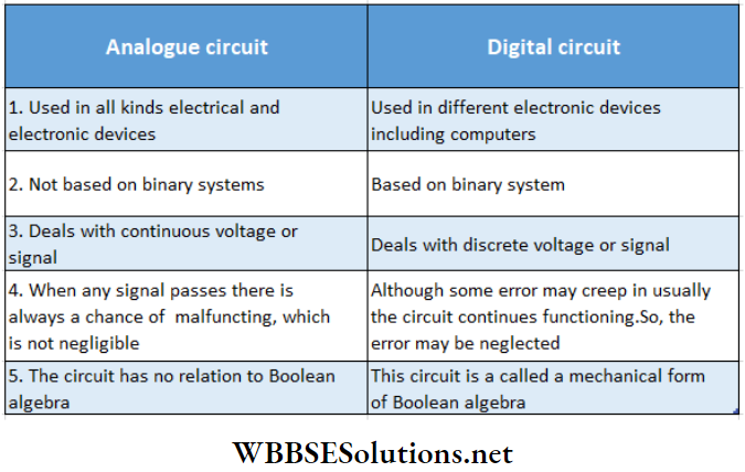
Question 1. What are the differences between analog circuits and digital circuits?
Answer:
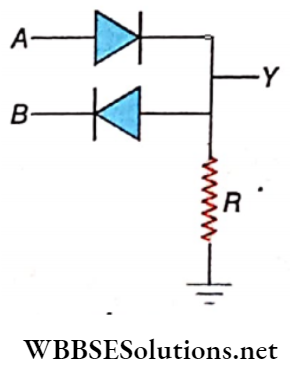
Question 2. Given a battery, two switches, and an electric bulb, how can
- An OR gate and
- An AND gate be constructed?
Answer:
If the switch is made on or off, the bulb glows or extinguishes. Hence, the two switches are the inputs, and the d bulb is the output
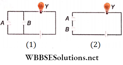
- The circuit is an OR gate circuit because when any one or both the switches, A and B are on, bulb Y will glow.
- The circuit is an AND gate circuit because only when both switches A and B are on, are the bulb Y glows.
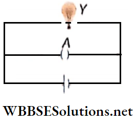
Question 3. Given n battery, a switch, and an electric lamp, how can a NOT gate be constructed?
Answer:
In this case, the switch is the input, and the electric bulb is the output, because when the switch is made ‘on’ or ‘off’ then the lamp goes ‘off’ or ‘on’ respectively. The circuit is a NOT gate circuit. When switch A is off, current flows through the lamp Y and it glows. When the switch is on, the entire current passes through the arm of the switch. As a result, the bulb extinguishes.(To avoid short circuits a low value resistance may be concentrated with switch A.
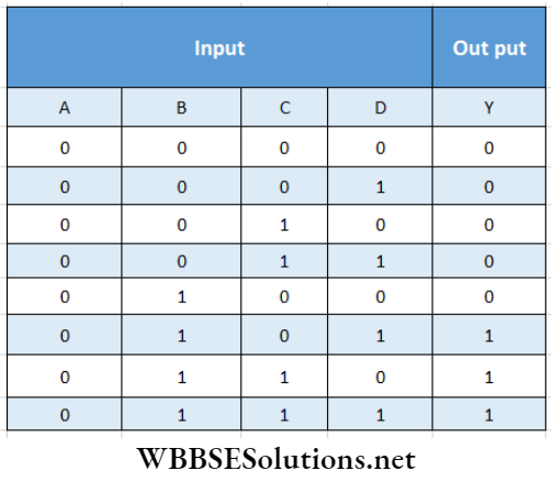
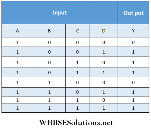
Question 6. Write down the truth table of the following circuit.
Answer:
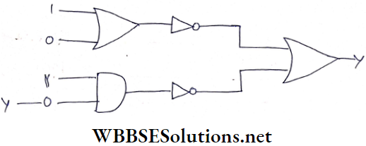
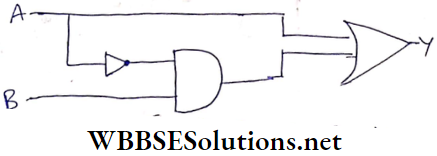
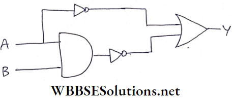
Question 4. What is the value of Y shown in the circuit given below?
Answer:
The output of the OR gate at the left-hand top is 1 and the output of the AND gate at the bottom is 0. These values change to 0 and 1, respectively after they pass through the two NOT gates.
Lastly, when it passes through the OR gate at the extreme right, the final output becomes, Y = 0 + 1 = 1
Y = \(\overline{1+0}+\overline{1 \cdot 0}\)
= \(\overline{1}+\overline{0}=0+1\)
= 1
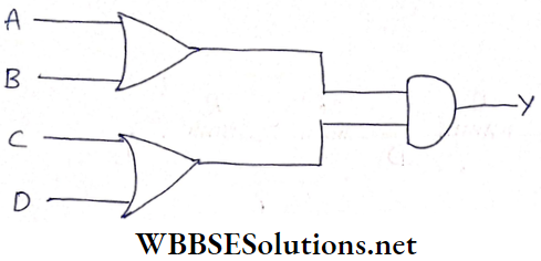
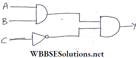
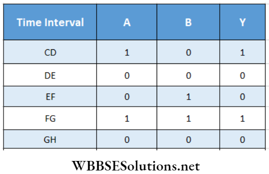
Question 5. In the given circuit diagram, If the output Y = I, what are the three inputs A, B, and C?
Answer:
For Y = 1, the two inputs of the AND gate on the right-hand side must be 1. Of them, the input at the top will be 1 if both A and B are 1; the input at the bottom will be 1 if C = 0. So, A = 1,B = 1,C = 0.
Alternative Answer:
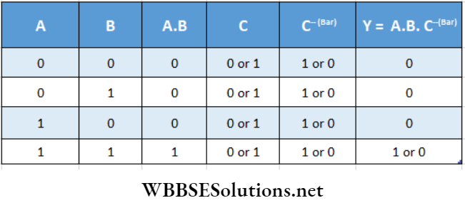
From truth table, it can be inferred that if A = 1 , B = 1 and C = 0 , then Y = 1
Question 6. An OR gate is operated by using positive logic. What role will the OR gate play if we use negative logic? Or, Show that the truth table of an OR gate in negative logic is similar to that of an AND gate in positive logic.
Answer:
In positive logic, lower and higher states are denoted by 0 and 1 respectively. According to this, the truth table of the OR gate is
- On the other hand, in negative logic, lower and higher states become 1 and 0 respectively. For this, 0 and 1 interchange their positions in the truth table. So, the new truth table
- Will be the same as the truth table of an AND gate in positive logic.
1.
2.
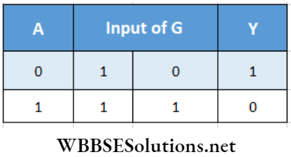
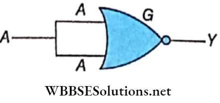
Question 7. How would you construct a NOT gate by using a NOR gate?
Answer:
Signal A has been divided into parts and applied simultaneously and the two Inputs of the NOR gate G. Out¬ put Y is shown In the truth table. It may be noticed that this table is the same as the truth table of NOT gate. So, it is possible to make a NOT gate by using a single NOR gate.
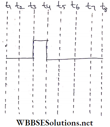
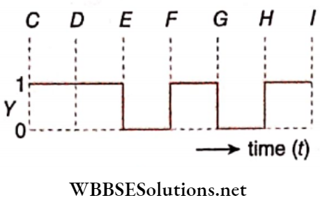
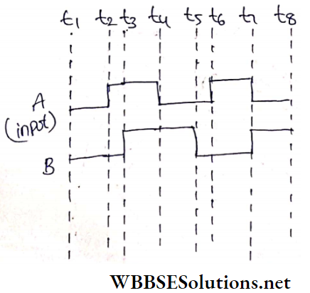
Question 8. The waveforms of two digital signals A and B are. If we apply these two signals A and B to an OR gate as inputs, then what will be the output waveform
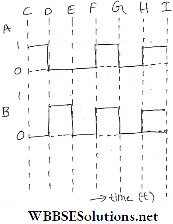
Answer:
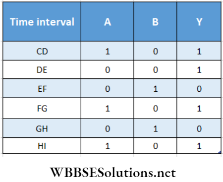
In different intervals of time, possible combinations of values 0 or 1 of A and B are shown in the truth table. From the truth table, the waveform of the output Y is
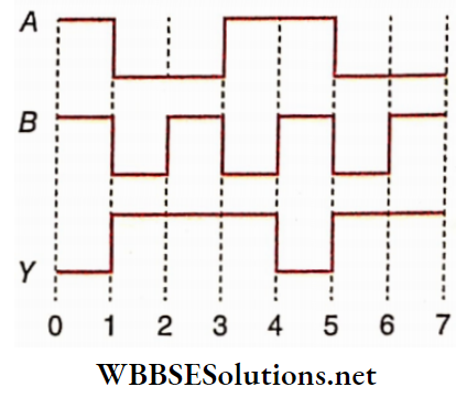
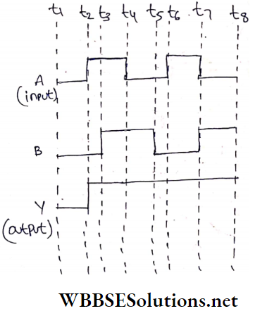
Question 9. Waveforms of two inputs A and B and output Y are. Find the Boolean algebraic equation of the associated logic gate and draw the circuit diagram of it.
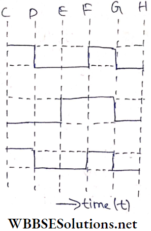
Answer:
From the given waveforms, we get the following truth table.
For this truth table, the Boolean algebraic equation of the associated gate is Y = A. The circuit diagram of associated logic
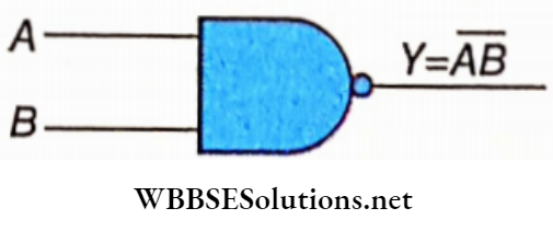
Question 10. Write the Boolean expression and the truth table for the logic circuit which is given
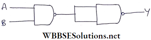
Answer:
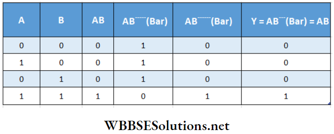
In this, we see that a NAND gate is followed by another NAND gate. Signals A and B are applied to the first NAND gate as inputs. Then the output of the first NAND gate AB is fed simultaneously to both inputs of the second NAND gate.
The output of the second NAND gate is AB i.e., AB. So, this logic circuit will act as an AND gate.
Hence, the Boolean algebraic equation is Y = AB.
The truth table of the given logic circuit is as follows:
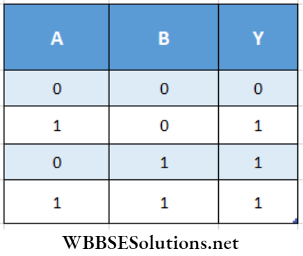
Question 11. Write the Boolean expression and truth table for the logic circuit which is
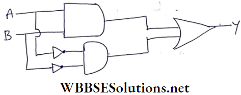
Answer:
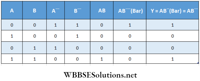
The Boolean expression for the given logic circuit is
Y= AB +\(\overline{A B}\)
The truth table of the given logic circuit is as follows:
Question 12. Find the Boolean expression of the given logic circuit. Draw the simplest logic circuit equivalent to this given logic circuit.
Answer:
The Boolean expression for the given logic circuit is
Y= A+\(\bar{A B}\)
Now, Y = A + \(\overline{A}\) B = A . 1+\(\overline{A}\) B = A(1+ B) +\(\overline{A}\) B
= A+ AB + \(\overline{A}\) B
= A + (A +\(\overline{A}\) )B = A + 1 .B
∴ Y = A + B
Hence, the equivalent circuit is an OR gate
Question 13. Two digital signals A and B shown in Fig. 2.46 are used as the two Inputs of
- OR
- AND
- NOR and
- NAND gate.
Obtain the output waveforms in each of the four cases
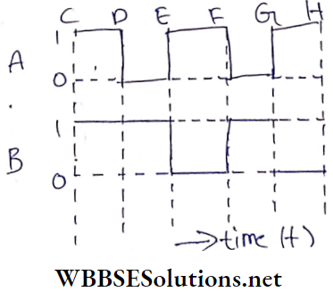
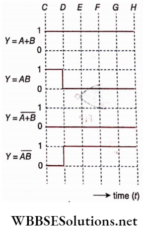
Answer: From the given waveforms, we get the following truth table
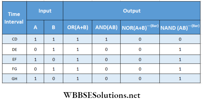
From this truth table, the output waveforms in each of the four cases are
Question 14. The required AND gate ( Y = AB). Find the Boolean expression of the given logic circuit. Draw the simplest logic circuit equivalent to this given circuit.
Answer: The Boolean expression for the given logic circuit is
Y = \(\bar{A}+\overline{A B}\)
Now, Y = \(\bar{A}+\overline{A B}\)
= \(\bar{A}+\bar{A}+\bar{B}\)
[∴ From De Morgan’s theorem, AB = A + B]
= \((\bar{A}+\bar{A})+\bar{B}=\bar{A}+\bar{B}\)
Y =\(\bar{A}+\bar{B}=\overline{A B}\)
Hence, the equivalent circuit is a NAND gate
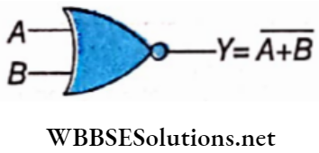
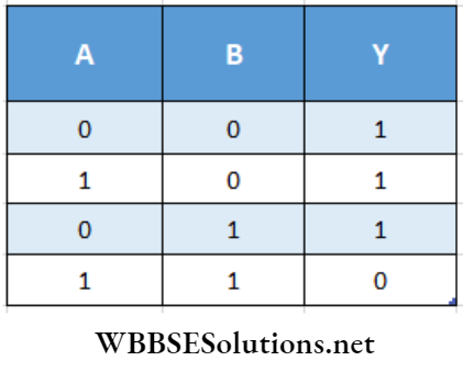
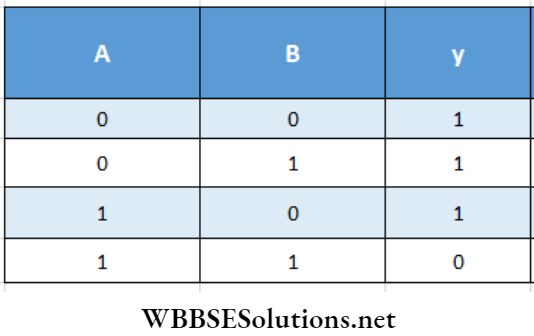
Question 15. Find the Boolean expression from the given truth table and draw its simplest logic circuit
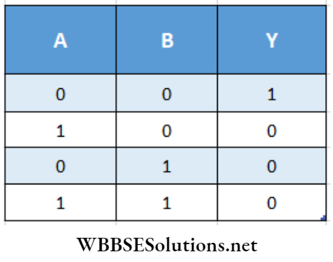
Answer:
Here, Y = 1 in only the first row of the truth table. Thus rest of the rows are not taken into consideration. In the first row, for A = 0 AND B = 0, write AB. Therefore, the Boolean expression is Y = \(\).
According to De Morgan’s theorem,
⇒ \(\overline{A+B}=\bar{A} \bar{B}\).
So, Y = \(\overline{A+B}\). It is the Boolean expression of the NOR gate. Hence, ‘ the simplest logic circuit is a NOR gate
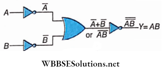
Question 16. How would you construct an AND gate by using mini¬ mum number of OR and NOT gates?
Answer:
Here, we have to use the following relations.
⇒ \(\bar{A}+\bar{B}=\overline{A B} \text { and } \overline{\overline{A B}}\)
The required AND gate ( Y = AB) is
Question 20. Find the Boolean expression from the given truth table and draw its simplest logic circuit.
Answer:
Here, Y = 1 in the first, second, and third rows of the truth table. Thus these three rows are to be taken into consideration.
For the first row, the Boolean expression is \(\bar{A} \bar{B}\). (∴ A = 0, B = 0 ),
For the second row, the Boolean expression is \(A \bar{B}\) (∴A = 1, B = 0) and
For the third row, the Boolean expression is \(\bar{A} B\) ( ∴ A = 0, B = 1 ).
So, the complete Boolean expression is Y = \(\bar{A} \bar{B}+A \bar{B}+\bar{A} B\)
By simplifying, we get,
Y = \(\bar{A} \bar{B}+A \bar{B}+\bar{A} B=(\bar{A}+A) \bar{B}+\bar{A} B\)
= \(1 \cdot \bar{B}+\bar{A} B\)
Since \(\bar{A}\) + A = 1
= \(\bar{B}+\bar{A} B=(1+\bar{A}) \bar{B}+\bar{A} B\)
Since 1 + \(\bar{A}\) = 1
= \(\bar{B}+\bar{A} \bar{B}+\bar{A} B\)
= \(\bar{B}+(\bar{B}+B) \bar{A}=\bar{B}+\bar{A}\)
i.e Y = \(\bar{A}+\bar{B}=\overline{A B}\) According to De Morgans theorem
It is the Boolean expression of the NAND gate. Hence, the simplest logic circuit is a NAND gate
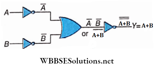
Question 17. How would you construct an OR gate by using a minimum number of AND and NOT gates?
Answer:
Here, we have to use the following relations.
⇒ \(\bar{A} \bar{B}=\overline{A+B} \text { and }\overline{\overline{A+B}}=A+B\)
The required OR gate ( Y = A + B) is
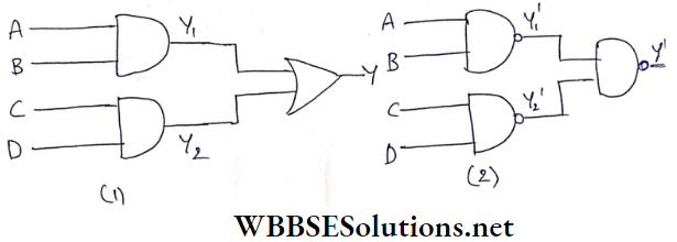
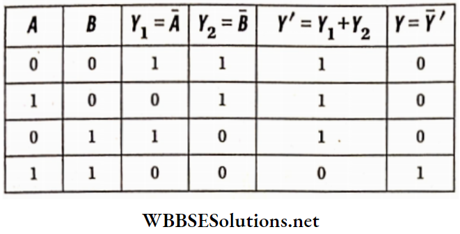
Question 22. Show that the two circuits 1, and 2 are equivalent to each other.
Answer:
Y1 = AB, Y2= CD
So, Y = AB + CD
Again
Y1 ‘= \(\overline{A B}\)
Y2 ‘= \(\overline{C D}\)
So, Y ‘ = \(\overline{Y_1^{\prime} Y_2^{\prime}}\)
= \(\bar{Y}_1^{\prime}+\bar{Y}_2^{\prime}\)
= \(\overline{\overline{A B}}+\overline{\overline{C D}}\)
= AB+ CD
Hence, Y’ = Y i.e., two circuits are equivalent to each other.
[Therefore, AND-OR combination is equivalent to NAND-NAND combination]
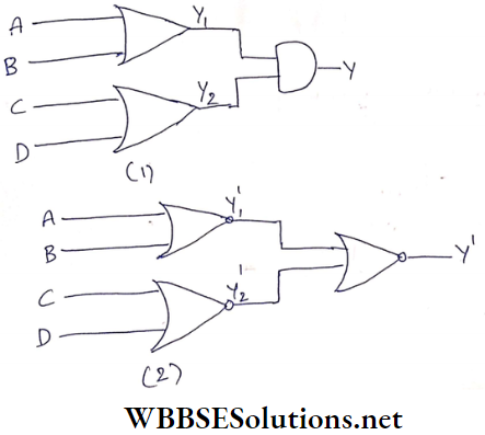
Question 18. Show that the two circuits 1,2 are equivalent to each other.
Answer:
Y1 = A +B, Y2 = C+D
So, Y = (A +B) + (C+D)
Again
Y’1= \(\overline{A+B}\)
Y’2= \(\overline{C+D}\)
So, \(\overline{Y_1^{\prime}+Y_2^{\prime}}=\left(\overline{Y_1^{\prime}} \cdot \overline{Y_2^{\prime}}\right)\)
= \((\overline{\overline{A+B}}) \cdot(\overline{\overline{C+D}})\)
= (A+B)(C+D)
Therefore, Y’ = Y i.e., two circuits are equivalent to each other. [Hence, OR-AND combination is equivalent to NOR-NOR combination]
Question 19. Two digital signals A and B are represented by two binary numbers 110011 and 100110 respectively. These two signals A and B are applied as inputs of
- OR
- AND
- NOR
- NAND gates.
Find the binary numbers to represent the outputs In each of the four cases.
Answer:
Two inputs A and B and outputs of
- OR (A + B),
- AND (AB),
- NOR (A + B), and
- NAND (AB)
Are shown in the truth table below:
So, the binary numbers representing the outputs are
- 110111
- 100010
- 001000 and
- 011101 respectively
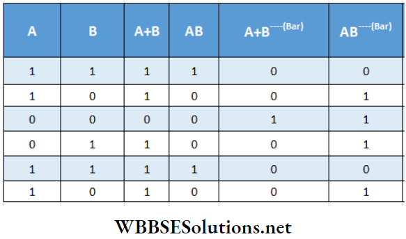
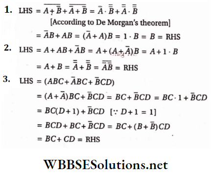
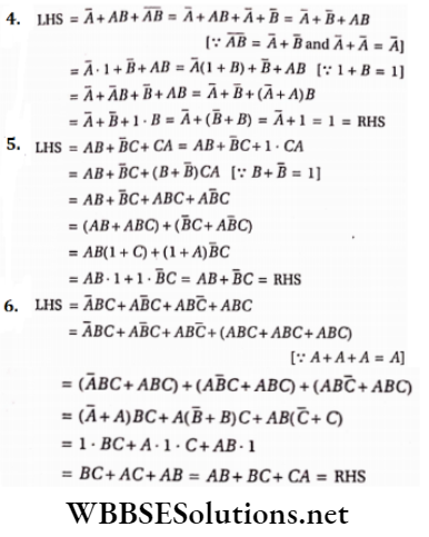
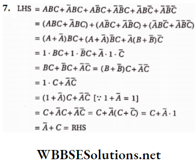
Question 20. Prove the following Boolean relations:
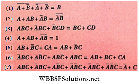
Answer:
Question 21. You are given two circuits. which consists of a NAND gate. Identify the logic operations carried out by the two circuits
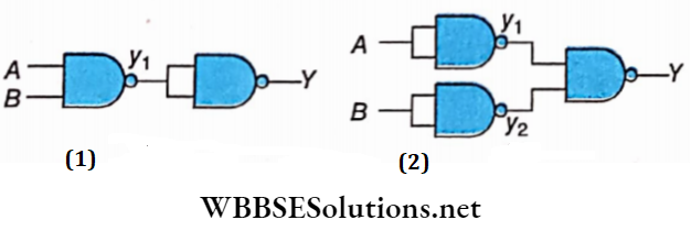
Answer:
In Y = \(\overline{y_1 \cdot y_1}=\bar{y}_1\)
∴ y1.y1 = y1
But y1 = \(\overline{A \cdot B}\)
Y = \(\overline{\overline{A \cdot B}}\)
(1) = Represents an AND operation.
In (2) Y = \(\overline{y_1 \cdot y_2}\)
But, Y1 = \(\overline{A \cdot A}\) = \(\overline{A}\)
Y = \(\overline{B \cdot B}\) = \(\overline{B}\)
Y = \(\overline{y_1 \cdot y_2}=\overline{\bar{A} \cdot \bar{B}}=\overline{\bar{A}}+\overline{\bar{B}}\)
= A+B
This represents an OR gate.
Question 22. You are given two circuits. Show that the circuit
- Acts as OR gate while the circuit
- Acts as AND gate
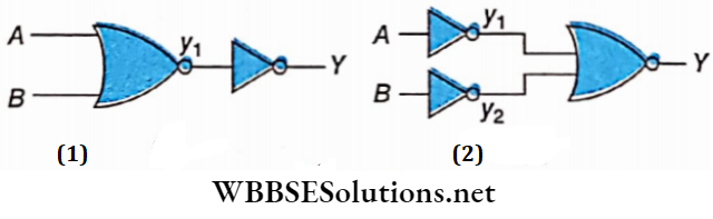
Answer:
In Y1 = \(\overline{A+B}\)
And Y = \(\overline{\overline{A+B}}\)
Y = \(\overline{\overline{A+B}}\) (Boolean algebra)
In, Y = \(\overline{y_1+y_2}=\bar{y}_1 \cdot \bar{y}_2\) (Using de Morgans theorem)
But y1= \(\bar{A}\)
y2 = \(\bar{B}\)
∴ Y = \(\bar{y}_1 \cdot \bar{y}_2\)
= \(\overline{\bar{A}} \cdot \overline{\bar{B}}\)
= A.B
Question 23. In the circuit identify the equivalent gate ofthe circuit
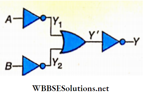
This is equivalent to an AND gate: Y = AB
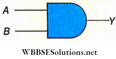
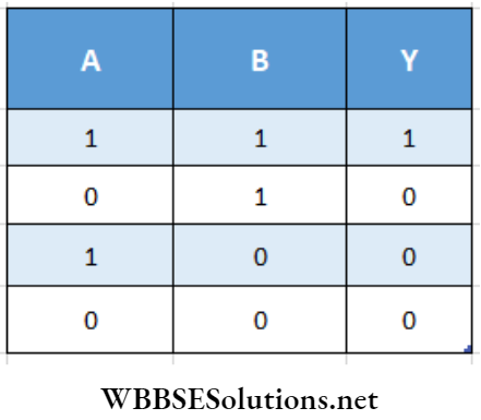
Question 24. Identify the gates P and Q shown in the figure. Write the truth table for the combination of the gates shown.
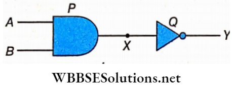
Name the equivalent gate representing this circuit and draw its logic symbol
Here P is a 2-input AND gate and Q is a NOT gate.
Truth Table:
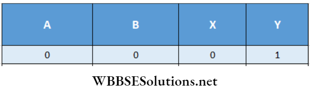
Now the equivalent gate ofthe given circuit represents the circuit action of a NAND gate. The logic symbol of the NAND gate. The logic symbol of the NAND gate is
Question 25. The following figure shows the input waveforms (A, B) and the output waveform (T) of a gate. Identify the gate, write its truth table, and draw its logical symbol
The truth table for the gate can be obtained from the waveform given
Therefore, from the above truth table, we can say that the gate is a NAND gate.
The logic symbol for the NAND gate is given below.
Question 26. The figure shows the Input waveforms A and B to a logic gate.
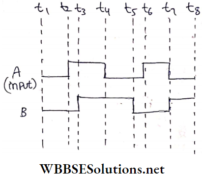
Answer:
4. The figure shows the Input waveforms A and B for the AND gate.
Output waveform will be as follows: