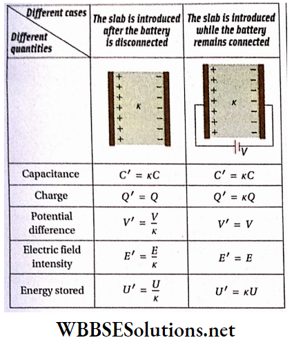
WBCHSE Class 12 Physics Electromagnetism Notes
Magnetic Effect Of Current And Magnetism
Magnetite, a black stone found in nature is called a natural magnet. It has two specific properties
- Attractive property
- Directive property.
1. Attractive property: Magnetite is found to attract pieces of iron.
2. Directive property:
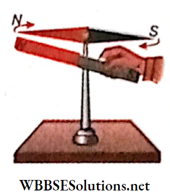
- If a piece of magnetite is suspended freely with the help of a thread, it aligns itself in the north-south direction.
- Navigators used magnetite as a compass for guiding their ships and hence it was called leading stone or lodestone.
- The two above-mentioned properties are called magnetic properties and the phenomenon is known as magnetism. Bodies showing these properties are called magnets.
- Magnetism is a physical property of matter because when a body is magnetized, no chemical change occurs.
Artificial Magnet:
Magnets found in nature have no definite shape. So the directive property cannot be understood clearly. Moreover, the attractive power of this magnet is weak and hence is not so useful.
Read and Learn More Class 12 Physics Notes
Later artificial magnets were invented for practical use. Using some special processes magnetic properties can be built up in iron, steel, nickel, and some alloys.
This process is known as magnetization and the magnets thus made are known as artificial magnets.
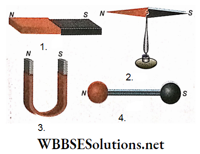
There are different shapes and sizes of artificial magnets:
- Bar magnet
- Magnetic needle
- Horseshoe magnet
- Ball-ended magnet etc.
North and South Poles of a Magnet:
If a bar magnet is dipped into some iron filings and then withdrawn, a good amount of filings clings at the two ends of the magnet but almost none at its middle
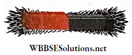
So, attractive power is maximum at the two ends of the magnet, and these two regions are called the poles of a magnet. The middle portion, where no attraction is observed, is called the neutral region.
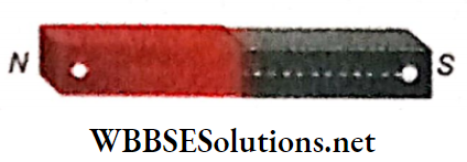
If a bar magnet is suspended freely by a thread, it sets itself at rest in the north-south direction. The pole of the magnet which always faces north is called the north pole (N-pole) or positive pole. Similarly, the pole facing south is called the south pole (S-pole) or negative pole of the magnet.
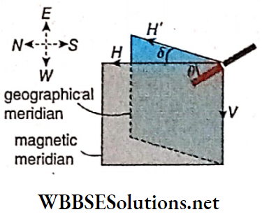
The line joining the two poles of a magnet is called the magnetic axis. If a magnet is suspended freely from its mid-point, it comes to rest after some time. The imaginary vertical plane through the magnetic axis of the magnet at this position is called the magnetic meridian of that place.
Usually, poles are considered as points and these two points lie very close to the ends of the magnet. The effective length of the magnet is about 80- 85% of its geometrical length.
If different magnets are dipped into iron filings and withdrawn, the amounts of iron filings collected are not the same in all cases. So, the attractive power of different magnets is different, but there is no difference between powerful and weak magnets with respect to the directive property.
WBCHSE Class 12 Physics Electromagnetism Notes Mutual Action Between Two Magnetic Poles:
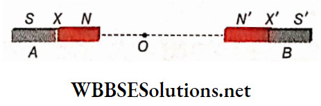
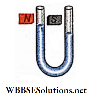
If the N-pole of a bar magnet is brought near the Af-pole of a magnetic needle, repulsion occurs between them, i.e., the Npole of the magnetic needle moves away from the bar magnet.
Again, if the N-pole of the bar magnet is brought near the S-poIe of the magnetic needle, they attract each other, i.e., the S-pole of the magnetic needle comes closer to the bar magnet.
If the experiment is performed with the S-pole of the bar magnet, the opposite action is observed, i.e., the S-pole of the bar magnet attracts the AT-pole of the magnetic needle but repels its S-pole.
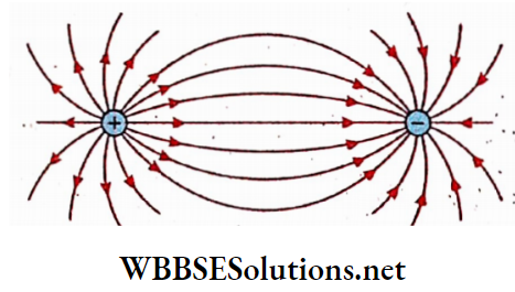
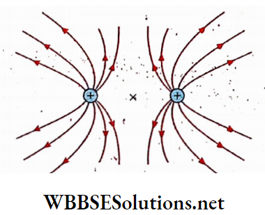
Inference: Like poles repel each other but unlike poles attract each other.
Repulsion Is the conclusive tost of magnetization:
If a body is repelled by a magnet, it is sure that the body is a magnet
If one end of a body Is brought near the Af-poles of a powerful magnet and if an attraction is observed between them there are two probabilities:
- The body may be an ordinary piece of iron
- The body is a magnet and the end under investigation is the S-pole of that magnet. So, attraction cannot Identify whether a body is a magnet or not.
But if repulsion instead of attraction Is observed In the above experiment, it is definite that the body is a magnet and the end under investigation is the iV-pole of that magnet.
Hence, repulsion is the conclusive test of magnetization.

WBCHSE Class 12 Physics Electromagnetism Notes
Magnetic Effect Of Current And Magnetism
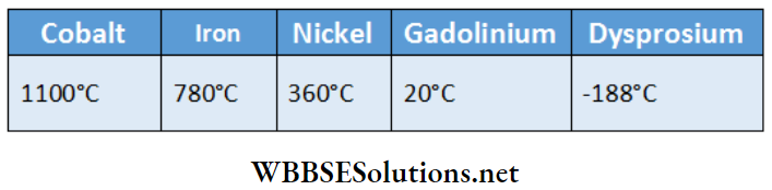
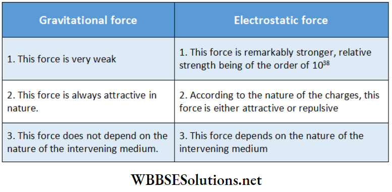
A magnet attracts iron, nickel, cobalt, and some metallic alloys. This force of attraction even penetrates the wood, glass, paper, or other obstructions. It is always observed that the influence of a magnet is felt in its surrounding region. The greater the distance from the magnet, the lesser is its influence. Again if a weak magnet is replaced by a stronger one, the range of this influence increases.
Magnetic Field Definition: The region surrounding a magnet in which the Influence of that magnet is felt, is called the magnetic field of that magnet.
Theoretically, the magnetic field of a magnet extends up to infinity; but In practice, the field Is assumed to be extended up to a limited region due to,
Limitation of the experimental arrangement used for identification
Presence of other magnetic fields (like Earth’s magnetic field) in the environment.
Magnetic Lines of Force or Field lines:
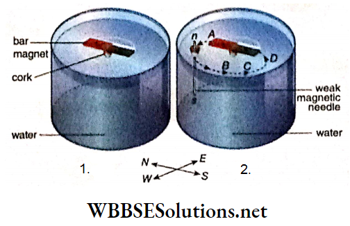
Experiment: A small but powerful bar magnet is kept on a fairly large piece of cork and is let to float on water kept in a large vessel. In the floating condition, the magnet ultimately sets Itself at rest along the Nordic-south direction.
So, its N-pole faces the north and the S-pole faces the sound. With the help of a small cork, a long but comparatively weak magnetic needle is set to float vertically on the water in such a manner that the n-pole of the needle is just above the water’s surface but its s-pole remains deep inside the water.
In this situation, the effect of the bar magnet on the s-pole of the needle becomes negligible due to its depth. Hence, the n-pole of the needle can be treated as an isolated free n-pole with respect to the bar magnet.
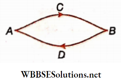
The N-pole of the needle is brought in contact with the N-pole of the bar magnet at point A and then released. It is seen that this n-pole moves over the surface of water and follows a curved path ABCD to reach the S-pole of the bar magnet
WBBSE Class 12 Electromagnetism Notes
Explanation of the experiment: The N-pole of the bar magnet exerts a force of repulsion on the isolated n-pole of the needle but the S-pole exerts a force of attraction on it.
The isolated free n-pole then starts moving along the resultant of the above two forces. At different points of the magnetic field of the bar magnet, the direction of this resultant force is different.
Then, the direction of motion of the n-pole will also change., So, when an isolated and free n-pole is allowed to travel in the magnetic field of a magnet, the pole describes a curved path and this path extends from the north pole to the south pole of the magnet.
A magnetic line of force is an imaginary curved line of a magnetic field; the direction of this field at any point is given by the tangent drawn at that point on the line of force passing through that point.
Class 12 Physics Electromagnetism Notes Properties of magnetic Hass of force:
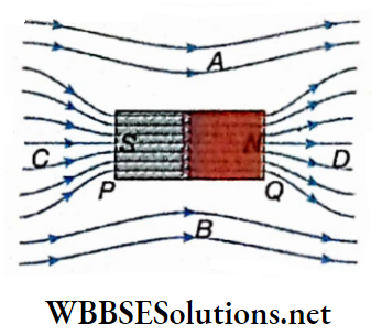
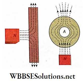
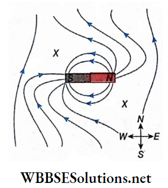
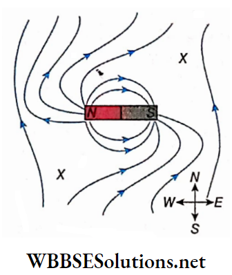
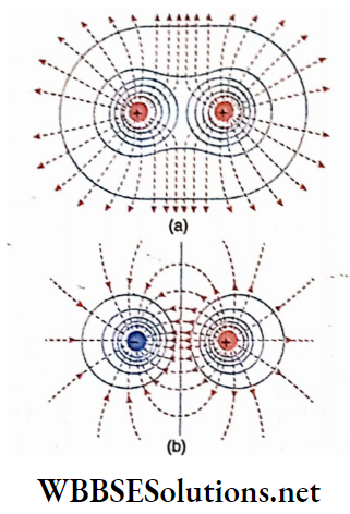
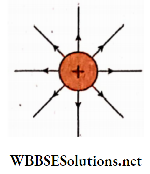
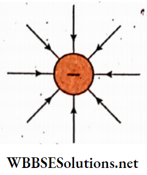
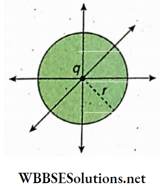
1. A magnetic line of force emerges from the north pole of a magnet and terminates at the south pole.
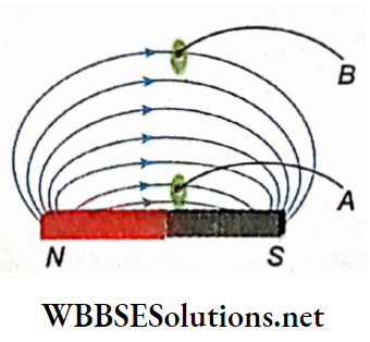
2. For different initial points adjacent to the north pole of a magnet, different lines of force are obtained in the magnetic field. Different lines of force at one side of a bar magnet are shown. A number of such lines of force indicate a magnetic field.
3. Two lines of force never intersect each other. If they intersect, through that point of intersection two tangents can be drawn on the two lines of force and each tangent will be the direction of the magnetic field at the point of inter the section. But two directions of the magnetic field at a single point are meaningless.
4. The concept of lines of force is totally imaginary, no such line exists in a magnetic field.
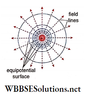
5. At any point in a magnetic field, if a unit area normal to the direction of the lines of force is imagined, the number of lines of force passing through that area is called the number density of the lines of force or magnetic flux at that point.
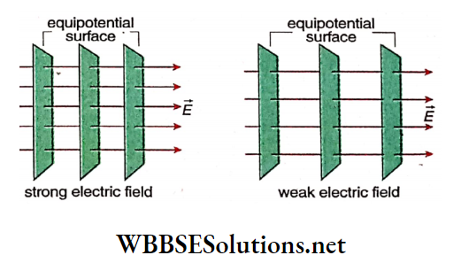
6. The greater this number density, the greater will be the strength of the magnetic field at that point For Example, the number density at point B is less than that at point A. So the magnetic field at point B is weaker than that at point A.
7. In general, the strength of a magnetic field is different at different points in that field and their directions are also different. Hence, the magnetic lines of force are usually curved lines at different distances.
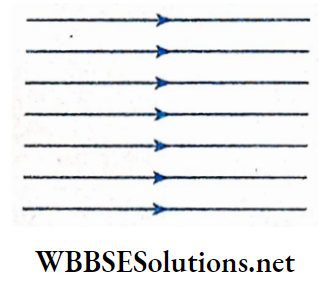
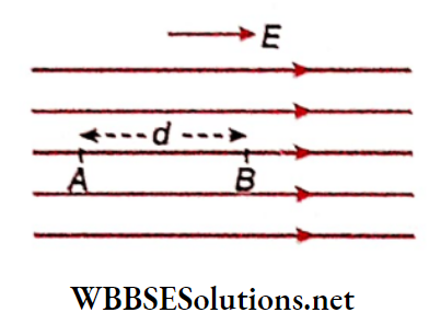
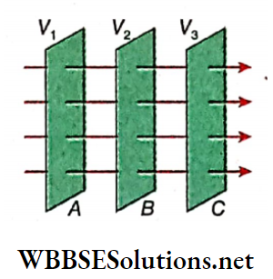
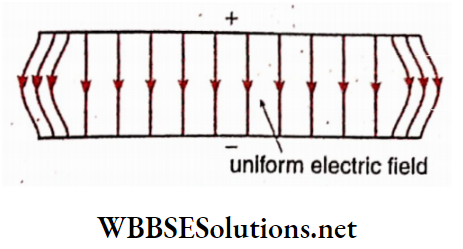
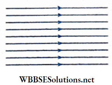
8. But if the magnetic field is uniform, i.e., its magnitude and direction are the same up to a certain region, then it can be represented by equispaced parallel straight lines. Earth’s magnetic field, very close to the surface of the earth, is such a uniform magnetic field.
Class 12 Physics Electromagnetism Notes
Electromagnetism Action Of Current On Magnets
Oersted’s Experiment:
In 1820, scientist Hans Christian Oersted discovered that a magnetic field is generated around a current-carrying conductor. He inferred this through the following experiment.
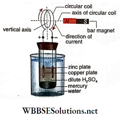
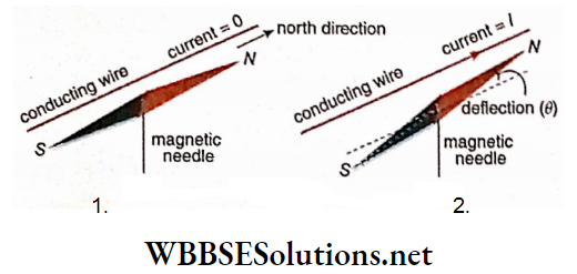
A magnetic needle is kept just below a conducting wire stretched along a north-south direction. The magnetic needle should be free to rotate about its vertical axis. Now if current is passed through the straight conductor with the help of an external source, the magnetic needle gets deflected, i.e., the needle undergoes an angular deflection θ
Observations related to deflection:
1. As soon as the current stops flowing through the wire, the magnetic needle rotates back to its initial position.
2. With the increase in current through the conducting wire, the angular deflection of the needle increases.
3. If the direction of the current in the conductor is reversed, the magnetic needle deflects in the opposite direction.
4. If the conducting wire is rotated slowly from its north-south direction while carrying current, the deflection of the magnetic needle gradually decreases. Ultimately when the direction of the current is along east-west, there will be no deflection of the magnetic needle.
5. So, when the conducting wire is placed normally to the axis of the magnetic needle and current is passed through the wire, no deflection of the magnetic needle is observed.
The direction of deflection of the magnetic needle due to the flow of electric current through the conductor can be determined with the help of any one of the following two rules:
1. Ampere’s swimming rule: If a man is imagined to be swimming along the direction of the current facing the magnetic needle with his arms outstretched, the north pole of the needle will be deflected towards his left hand
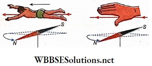
2. Right-hand thumb rule: The right hand, with its thumb sticking out, is held in. Such a way that the conducting wire is in between the palm and the magnetic needle. If the other fingers point the direction of the current then the thumb will indicate the direction of deflection of the north pole of the needle.
WBCHSE Physics Electromagnetism Study Material
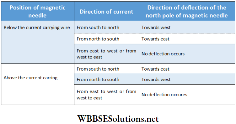
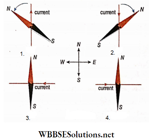
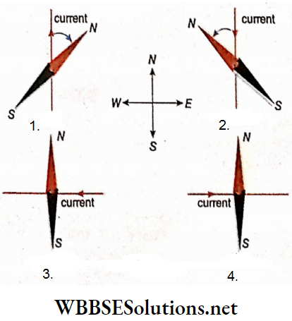
The direction of deflection of the magnetic needle is shown in the following table:
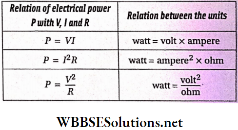
Key Formulas in Electromagnetism for Class 12
WBCHSE Physics Electromagnetism Study Material Discussions:
1. Dependence of magnetic field: At any adjacent point of a current-carrying conductor, the magnitude of the magnetic field depends on the magnitude of current and the direction of the magnetic field depends on the direction of current and on the position of the point with respect to the current-carrying conductor.
2. Presence of insulating material: The magnetic field is not affected if the current-carrying conductor is covered with an insulating material.
3. Current-carrying material: The current-carrying conductor itself is not magnetized. If some iron filings are brought in contact with the conductor, no attraction is observed.
4. Magnetic field due to a moving charged particle: The motion of charged particles is the cause of electric current. Hence, a moving charge can produce a magnetic field around it. Obviously, when a charged particle is at rest, it cannot produce a magnetic field.
Mapping of Magnetic Lines of Force due to an Electric Current:
Any magnetic field can be represented by magnetic lines of force. The direction of the magnetic field at any point is denoted by the direction of the magnetic line of force at that point. To determine the direction of the magnetic field at any point around a current-carrying conductor, either of the following two rules can be used.
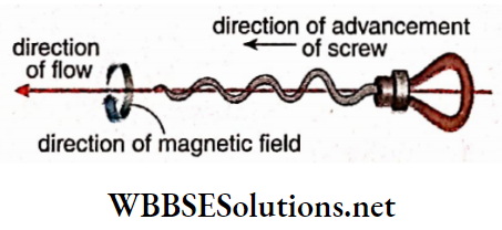
1. Maxwell’s corkscrew rule: If we imagine a right-handed corkscrew to be driven along the direction of current in a conductor, then the direction in which it rotates, gives the direction of the magnetic field.
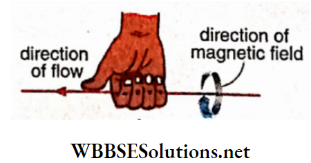
2. Right-hand grip rule: If a current-carrying conductor is imagined to be held within the grip of the right hand and if the direction of current through the conductor is indicated by the thumb, direction then the other fingers will curl in the direction of the magnetic field.
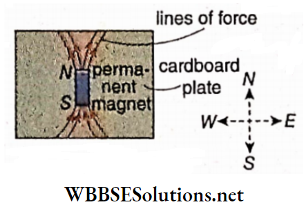
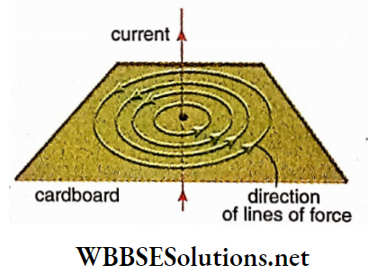
Long straight conductor: A long straight conducting wire carrying current is passed through the center of a cardboard and the cardboard is held normally to the length of the wire.
Some light iron filings are scattered over the cardboard. Now if the cardboard is slightly tapped, the iron filings arrange themselves in some concentric circles around the conducting wire. These concentric circles indicate the magnetic lines of force on a plane perpendicular to the current carrying a long straight conductor.
With the help of the corkscrew rule, the direction of the lines of force can also be determined. For an upward current, the directions of the magnetic lines of force. If the direction of current flow is reversed, i.e., for a downward current, the direction of the lines of force will also be reversed.
In the laboratory, generally, a magnetic needle is used instead of iron filings for plotting magnetic lines of force.
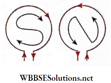
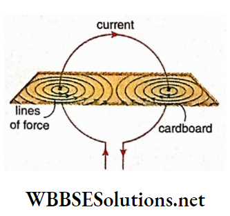
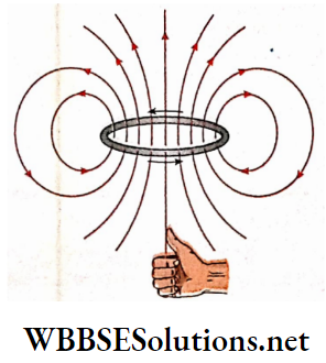
Circular conductor: A circular current-carrying conductor is shown in penetrating a cardboard plate kept perpendicular to the plane of the circular conductor.
With the help of iron filings or a magnetic needle, if the lines of force of the magnetic field are drawn on the cardboard.
The directions of the magnetic lines of force may be determined by the corkscrew rule. If the direction of current in the circular conductor is reversed, the directions of the lines of force will also get reversed.
It is to be noted here that, at the centre of the circular conductor the lines of force are almost parallel to the axis going through the center.
Electromagnetism Notes For Class 12 WBCHSE
Electromagnetism Biot-Savart Law Or Laplace’s Law
A diagrammatic representation of a magnetic field is its representation using magnetic lines of force:
1. The direction of the tangent drawn at any point on a magnetic line of force is the direction of the magnetic field at the point;
2. Comparing the number density of magnetic lines of forces at different points in a magnetic field, the field strengths at those points can be compared. But to define magnetic field precisely as a definite physical quantity, at every point its magnitude should be represented by a number and an associated unit. This is not possible from the concept of magnetic lines of force only.
As a physical quantity, the usual symbol of the magnetic field is \(\vec{B}\) (as it is a vector). This vector B is named magnetic field magnetic induction or magnetic flux density. In the region surrounding a current-carrying conductor
- The direction of \(\vec{B}\) is determined by Maxwell’s corkscrew rule
- The magnitude of \(\vec{B}\) (i.e., B) is determined by Biot-Savart law.
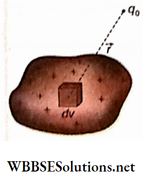
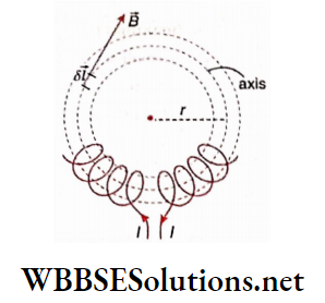
Statement of Biot-Savart law:
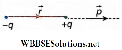
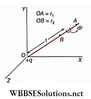
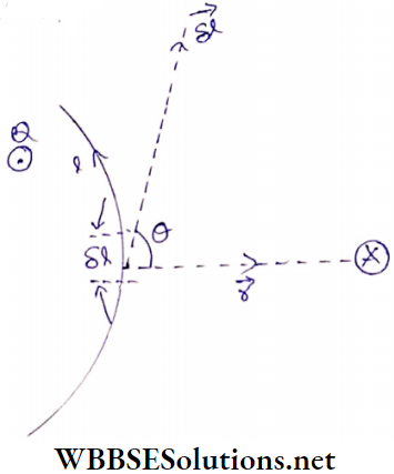
Let δl= a small elementary part of a conducting wire
I = current through the wire
r = distance of any external point from the element δl
θ = angle between the element \(\delta \vec{l}\) and the position vector -r of the external point
δB = magnitude of the magnetic field at that external point.
Then the Biot-Savart law states that,
- \(\delta B \propto \delta l\)
- \(\delta B \propto I\)
- \(\delta B \propto \frac{1}{r^2}\)
- \(\delta B \propto \sin \theta\)
This means, \(\delta B \propto \frac{I \delta l \sin \theta}{r^2} \text { or, } \delta B=k \frac{I \delta l \sin \theta}{r^2}\)….(1)
This law is also called Laplace’s law. The value of the constant k in equation (1) depends on
1. The nature of the medium between the conductor and the point under consideration and
2. The system of units used for different physical quantities. In this chapter, we shall consider only vacuum as the medium.
SI unit: SI units of different physical quantities used in equation (1) are:
δl and r: meter (m); I: ampere (A); δB: weber/metre2 (Wb.m-2) or tesla (T).
For the definition of the unit of magnetic field (Wb.m-2)
If these units are used in equation (1) then another constant is traditionally used instead of k. This constant is μ0 = 4πk,
⇒ \(k=\frac{\mu_0}{4 \pi}\)
So, the usual form of Biot-Savart law in vacuum,
⇒ \(\delta B=\frac{\mu_0}{4 \pi} \cdot \frac{I \delta l \sin \theta}{r^2}\)….(2)
The constant μ0 is called the permeability of free space.
Unit of μ0: From equation (2),
⇒ \(\mu_0=\frac{4 \pi r^2 \delta B}{I \delta l \sin \theta}\)
∴ The unit of \(\mu_0=\frac{\mathrm{m}^2 \times \mathrm{Wb} \cdot \mathrm{m}^{-2}}{\mathrm{~A} \times \mathrm{m}}=\mathrm{Wb} \cdot \mathrm{A}^{-1} \cdot \mathrm{m}^{-1}\)
Here, Wb.A-1 is also called Henry (H).
Hence, the unit of μ0 is henry/metre (H.m-1)
Value of μ0: = 4π x 10-7 H m-1.
It is to be noted that,
⇒ \(\frac{\mu_0}{4 \pi}=10^{-7} \mathrm{H} \cdot \mathrm{m}^{-1}\)
Biot-Savart law for extended conductors: An extended conductor is assumed to be composed of a number of smaller parts \(\delta l_1, \delta l_2, \cdots\), etc. and the Biot-Savart law is applied for each part. At any point, the magnetic field due to the whole conductor will be,
⇒ \(B=\sum \delta B=\frac{\mu_0}{4 \pi} \sum \frac{I \delta l \sin \theta}{r^2}\)
The \(\) (summation) sign indicates the sum of a number of terms. \(\vec{B}\) is a vector; so to determine the resultant, the rule of vector addition is applied. Usually, this vector addition is very complicated. But in the case of symmetrical conductors like straight conducting wire, circular coil, etc., determination of the resultant magnetic field is not so troublesome.
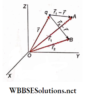
Vector form of Wot-Savort low: If the unit vector towards the point P with respect to \(\delta l \text { be } \hat{r} \text {, then } \vec{r}=r \hat{r}\).
Hence, the magnitude of the vector product \((\delta \vec{l} \times \hat{r})\) is,
⇒ \(|\delta \vec{l} \times \hat{r}|=\delta l \cdot 1 \cdot \sin \theta=\delta l \sin \theta \quad[∵|\hat{r}|=1]\)
Again, the direction of \((\delta \vec{l} \times \hat{r})\) is downward with respect, which is actually the direction of the magnetic field as per the corkscrew rule. So, the vector form of the equation (2) is,
⇒ \(\delta \vec{B}=\frac{\mu_0}{4 \pi} \cdot \frac{I \delta \vec{l} \times \hat{r}}{r^2}\)….(3)
From equation (3) we get,
⇒ \(\vec{B}=\frac{\mu_0}{4 \pi} \sum \frac{I \delta \vec{l} \times \hat{r}}{r^2}=\frac{\mu_0}{4 \pi} \sum \frac{I \delta \vec{l} \times \vec{r}}{r^3}\)….(4)
Usually with respect to the plane of the paper, an upward vector is denoted by \(\odot\) sign to mean the tip of an arrow and a downward vector by \(\otimes\) sign to mean the tail of an arrow. Thus, the direction of the magnetic field at point P is denoted by the \(\otimes\) sign, and at point Q, \(\odot\) sign is used.
The magnetic intensity or magnetic field strength or magnetizing field:
In SI: The magnetic permeability of vacuum is μ0 this value of μ0 is also used for air because, in the presence of air, no remarkable change in the magnetic field is observed.
But for any other medium, the permeability of that medium is denoted by n. For different media the magnitude of μ is different. In the case of any medium, the general form of Biot-Savart law is,
⇒ \(\delta B=\frac{\mu}{4 \pi} \cdot \frac{I \delta l \sin \theta}{r^2}\)….(5)
From equations (2) and (5) we see that the quantity \(\frac{1}{4 \pi} \cdot \frac{I \delta l \sin \theta}{r^2}\) can be treated as the cause of the magnetic field in a medium. In the absence of the multiplier μ0 or μ in this expression, this quantity does not depend on the medium. To determine the magnetic field in a medium, this quantity is just multiplied by the magnetic permeability of that medium. This quantity is called magnetic intensity or magnetizing field. It is expressed by H.
From the equation (5) we can write,
⇒ \(\delta B=\frac{\mu}{4 \pi} \cdot \frac{I \delta l \sin \theta}{r^2}=\mu \delta H\)
where, \(\delta H=\frac{1}{4 \pi} \cdot \frac{I \delta l \sin \theta}{r^2}\)…(6)
Generally, \(B=\mu H \quad \text { or, } \quad H=\frac{1}{\mu} B\)
Like \(\vec{B}\), H is also a vector quantity whose direction is the same
as that of \(\vec{B}\).
So, \(\vec{B}=\mu \vec{H} \quad \text { or, } \quad \vec{H}=\frac{1}{\mu} \vec{B}\)…(7)
With the help of this equation (7), \(\vec{H}\) can be defined.
Definition: At any point in a medium the ratio of the acting magnetic, field and the magnetic permeability of the medium is called the magnetic intensity or magnetizing field at that point.
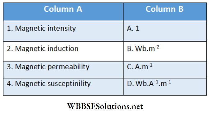
Unit: Unit of \(H=\frac{\text { unit of, } B}{\text { unit of } \mu}=\frac{\mathrm{Wb} \cdot \mathrm{m}^{-2}}{\mathrm{~Wb} \cdot \mathrm{A}^{-1} \cdot \mathrm{m}^{-1}}\)
= A.m-1 (ampere/metre)
CGS or Gaussian system:
In this system \(\vec{H}\), i.e., the magnetic intensification (instead of \(\vec{B}\)) is considered as the primary vector in magnetism. In this case, the unit of magnetic intensity H is d (Oe) arid the unit of magnetic field B is gauss (G). It may be of interest to note that 1 oersted is the same as 1 dyn per unit pole, and 1 gauss is the same as 1 maxwell/cm2 according to the old definition of magnetic intensity.
Relation between SI and CGS units:
1 A.m-1 = 4π x 10-3 Oe, 1 Wb.m-2 = 10-4 G
In the CGS system, the electromagnetic, unit (abbreviated as emu) of current is used as the unit of current and is expressed by the symbol i. This electromagnetic unit is so defined that if the other quantities in equation (6) are expressed in CGS units, thÿf-,ÿ constant \(\frac{1}{4 \pi}\) can be replaced by 1. In that case, the CGS form of the equation will be,
⇒ \(\delta H=\frac{i \delta l \sin \theta}{r^2}\)…(8)
So, the different units used in this equation are
δl and r: cm; i: emu of current; δH: Oe.
This equation (δ) indicates the Biot-Savart law or Laplace’s law in the CGS or Gaussian system.
Emu current: The current which, when flowing through a conducting wire of length in the form of an arc of a circle of radius 1 cm, produces a magnetic Intensity of 1 Oe at the center of the arc, is called 1 electromagnetic unit (emu) of current
The two parts of the wire except the circular are kept along the radius of the circle; thus no magnetic field is produced at the center of the circle due to the current flowing through these two parts.
The definition of the electromagnetic unit of current can be explained from the discussion of the magnetic field produced due to current in a circular conductor
Relation between ampere and emu of current:
1 emu of current = 10 A
Rules of conversion from SI to CGS:
The following replacements convert SI expressions into the corresponding ones. CGS expressions;
1. Magnetic intensity \(\vec{H}\), in place of magnetic field \(\vec{B}\);
2. Electric current in the emu, in place of I in amperes;
3. The constant 1 in place of \(\frac{\mu_0}{4 \pi}\), i.e., 4π in place of μ0
Application of Biot-Savart Law Long Straight Conductor:
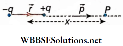
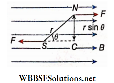
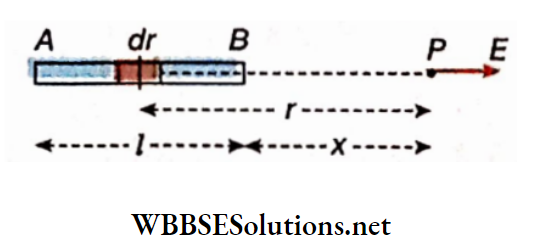
Let I = strength of current in an electrical circuit. AB is a straight conductor and OP = r = perpendicular distance of the point P from the current carrying wire.
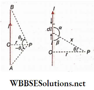
The two endpoints of the conducting wire make angles θ1 and θ2 at point P with respect to OP. In the direction of the current, if the angle θ2 is taken as positive then in the opposite direction, θ1 will be negative, i.e., it will be -θ1.
The conducting wire and its adjacent region in a magnified form. From a very small part dl of the wire, the distance of the point P is x and the angle between the direction of current and x is a.
So, according to Iliot-Savnrt law, the magnitude of the magnetic field at die point P due to dl is,
⇒ \(d B=\frac{\mu_0}{4 \pi} \cdot \frac{I d l \sin \alpha}{x^2}\)…(1)
From the diagram,
⇒ \(\alpha=180^{\circ}-\beta=180^{\circ}-\left(90^{\circ}-\theta\right)=90^{\circ}+\theta\)
So, sinaaa = sin(90° + θ) = cosθ ….(2)
Again, l = rtanθ
Since, r = constant, differentiating the equation we get,
dl = rsec²θdθ….(3)
Again, cosθ = \(\frac{r}{x}\)
or, \(x^2=\frac{r^2}{\cos ^2 \theta}=r^2 \sec ^2 \theta\)…..(4)
Now putting the values of sinaaa, dl, and x2 from equations (2), (3), and (4) into equation (1) we get,
⇒ \(d B=\frac{\mu_0}{4 \pi} \cdot \frac{I \cdot r \sec ^2 \theta d \theta \cdot \cos \theta}{r^2 \sec ^2 \theta}=\frac{\mu_0}{4 \pi} \cdot \frac{I}{r} \cdot \cos \theta d \theta\)….(5)
So, for the entire wire AB, the magnetic field at the point P is,
⇒ \(B=\int d B=\frac{\mu_0}{4 \pi} \cdot \frac{I}{r} \int_{-\theta_1}^{\theta_2} \cos \theta d \theta\)
⇒ \(\frac{\mu_0}{4 \pi} \cdot \frac{I}{r}[\sin \theta]_{-\theta_1}^{\theta_2}=\frac{\mu_0}{4 \pi} \cdot \frac{I}{r}\left[\sin \theta_2-\sin \left(-\theta_1\right)\right]\)
⇒ \(\frac{\mu_0}{4 \pi} \cdot \frac{I}{r}\left(\sin \theta_2+\sin \theta_1\right)\)
So, \(B=\frac{\mu_0}{4 \pi} \cdot \frac{I}{r}\left(\sin \theta_1+\sin \theta_2\right)\)…(6)
This is the expression for the magnitude of the magnetic field at point P due to the current carrying wire.
Special cases:
For infinitely long conducting wire: Let the length of the wire below the point O be Ll and above this point, I². If these two lengths are much greater than r, i.e., and r<<I², the wire can be treated as of infinite length with respect to the point P. In that case, for the lowermost end of the wire,θ1 ≈ 90° and for the uppermost end of the wire θ2 ≈ 90°.
So from the equation (6), we can write,
⇒ \(B=\frac{\mu_0}{4 \pi} \cdot \frac{I}{r}\left(\sin 90^{\circ}+\sin 90^{\circ}\right)\)
∴ \(B=\frac{\mu_0}{4 \pi} \cdot \frac{2 I}{r}\)…(7)
For semi-infinitely long conducting wire: Let the lowermost end of the wire be O and the length of the wire = I. If r<<L, the wire can be called semi-infinitely long with respect to the point P. In that case, θ1 = 0° and θ2 = 90°.
So, from the equation (6), we can write
⇒ \(B=\frac{\mu_0}{4 \pi} \cdot \frac{I}{r}\left(\sin 0^{\circ}+\sin 90^{\circ}\right)\)
∴ \(B=\frac{\mu_0}{4 \pi} \cdot \frac{I}{r}\)…(8)
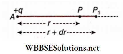
For a point on the extended part of the wire: If point P1 is located according to, both θ1 and θ2 will be negative with respect to r which is the perpendicular distance between point P1 and the extension of the wire AB.
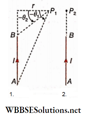
So, the magnetic field at P1,
⇒ \(B_1=\frac{\mu_0}{4 \pi} \cdot \frac{I}{r}\left[\sin \theta_1+\sin \left(-\theta_2\right)\right]\) [taking θ2 negative in equation (6)]
⇒ \(\frac{\mu_0}{4 \pi} \cdot \frac{I}{r}\left(\sin \theta_1-\sin \theta_2\right)\)…..(9)
If we consider the point P2 to lie on the extension of the wire AB, then θ1 = 90° and θ2 = 90°. Putting these in equation (9) we get, the magnetic field at the point P2,
⇒ \(B_2=\frac{\mu_0}{4 \pi} \cdot \frac{I}{r}\left[\sin 90^{\circ}-\sin 90^{\circ}\right]=\frac{\mu_0}{4 \pi} \cdot \frac{I}{r}[1-1]=0\)
So, at any point lying along the length of a current-carrying conductor, the magnetic field due to that conductor will be zero.
Expressions in CGS or Gaussian system: In the above-mentioned equations (6), (7), and (8), if we substitute B→H, I→I, and μ0→4π then we get
Magnetic intensity due to a straight conductor,
⇒ \(H=\frac{i}{r}\left(\sin \theta_1+\sin \theta_2\right)\)
Magnetic intensity due to an infinitely long conductor,
⇒ \(H=\frac{2 i}{r}\)
Magnetic intensity due to a semi-infinitely long conductor,
⇒ \(H=\frac{i}{r}\)
Magnetic Effect Of Current And Magnetism
Electromagnetism Numerical Examples
Short Answer Questions on Electromagnetism
Example 1. The distance between two long straight conductors is 5m. Currents 2.5 A and 5 A are flowing through in the same direction. What will be the magnetic field at a themed point between them?
Solution:
According to the corkscrew rule, the magnetic fields at the mid-point due to die two conductors will be opposite in directions.
So, the relation, \(B=\frac{\mu_0}{4 \pi} \cdot \frac{2 I}{r}, \text { gives }\)
magnetic field at the mid-point due to the first conductor,
⇒ \(B_1=\frac{\mu_0}{4 \pi} \cdot \frac{2 I_1}{\frac{r}{2}}=\frac{\mu_0}{4 \pi} \cdot \frac{4 I_1}{r}\)
and magnetic field at the mid-point due to the second conductor,
⇒ \(B_2=\frac{\mu_0}{4 \pi} \cdot \frac{2 I_2}{\frac{r}{2}}=\frac{\mu_0}{4 \pi} \cdot \frac{4 I_2}{r}\)
⇒ \(I_2>I_1 \text { and hence } B_2>B_1\)
∴ The resultant magnetic field,
⇒ \(B=B_2-B_1=\frac{\mu_0}{4 \pi} \cdot \frac{4}{r}\left(I_2-I_1\right)\)
⇒ \(\frac{\mu_0}{4 \pi} \cdot \frac{4}{5}(5-2.5)=\frac{4 \pi \times 10^{-7}}{4 \pi} \times \frac{4}{5} \times 2.5\) [∵ r = 5m, I1 = 2.5 A, I2 = 5 A]
= 2 x 10⁻⁷ T
Example 2. 5 A current Is flowing in two opposite directions through each of two parallel straight conducting wires kept 0.2 m apart. find who second wins) Determine the magnitudes and directions of the magnetic field at the points P, Q, and R lying on the plane containing the two wires.
Solution:
The magnetic field at P due to the first wire,
⇒ \(B_1=\frac{\mu_0}{4 \pi} \cdot \frac{2 \times 5}{0.1} \text { (upward) }\)
The magnetic field at P due to the second wire,
⇒ \(B_2=\frac{\mu_0}{4 \pi} \cdot \frac{2 \times 5}{0.3} \text { (downward) }\)
Since, B1 > B2, the resultant magnetic field will be upward from the plane.
∴ Bp = B1 – B2
⇒ \(\frac{\mu_0}{4 \pi}(2 \times 5)\left(\frac{1}{0.1}-\frac{1}{0.3}\right)\)
⇒ \(10^{-7} \times 10 \times 10 \times \frac{2}{3}\)
⇒ \(6.67 \times 10^{-6} \mathrm{~Wb} \cdot \mathrm{m}^{-2}\)
Similarly, the upward magnetic field at the point Q,
BQ = 6.67 x 10⁻⁶ Wb.m-2
At point R, the magnetic field due to the first wire as well as for the second wire is downward. Hence, the resultant magnetic field will be the sum of these two fields.
So, \(B_R=2 B_1=2 \times \frac{\mu_0}{4 \pi} \cdot \frac{2 \times 5}{0.1}\)
= 2 x 10-7 x 10 x 10
= 2 x 10⁻⁵ Wb.m-2
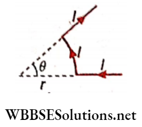
Example 3. An infinitely long conducting wire POQ is bent through right angles at O. If a current I . 0 is sent through this bent wire, what will be the magnitude of the magnetic field at point A at a distance r from each part of the wire?
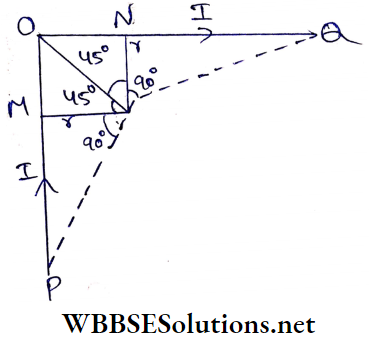
Solution:
AM = AN = r
So, ∠OAM = ∠OAN = 45°
Now, the magnetic field at A due to PO is equal to that due to OQ both in magnitude and direction (downwards). Again, the points P and Q make angles at A relative to AM and AN. For infinitely long wires, each of these angles is close to 90°.
So the resultant magnetic field at A is
⇒ \(B=2 \times \frac{\mu_0}{4 \pi} \cdot \frac{I}{r}\left(\sin 90^{\circ}+\sin 45^{\circ}\right)\)
⇒ \(\frac{\mu_0}{4 \pi}: \frac{I}{r}(2+\sqrt{2}) \text { (directed downwards) }\)
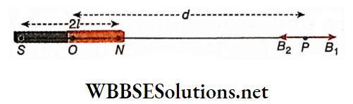
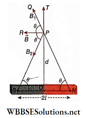
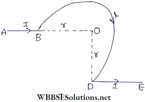
Example 4. Through each of two wires POQ and P’O’Q’ an electric current I is passing. P The points Q, O, O’, and Q’ are collinear. Determine the magnetic field at the midpoint A of OO’.
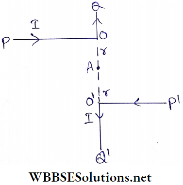
Solution:
Point A lies along the length of the two parts OQ and O’Q’. Hence, no magnetic field exists at A due to these two parts.
The two parts PO and P’O’ are semi-infinite conducting wires with respect to point A. Hence, for each part, the magnetic field at \(A=\frac{\mu_0}{4 \pi} \cdot \frac{I}{r}\) and these two fields are downwards.
Hence, the downward magnetic field at the point A,
⇒ \(B=\frac{\mu_0}{4 \pi} \cdot \frac{I}{r}+\frac{\mu_0}{4 \pi} \cdot \frac{I}{r}=\frac{\mu_0}{4 \pi} \cdot \frac{2 I}{r}\)
Applications of Electromagnetism in Daily Life
Example 5. 5 A current is flowing through a long straight conducting wire. What is the magnitude of the magnetic field at a distance of 10 cm from the wire?
Solution:
We know, \(B=\cdot \frac{\mu_0}{4 \pi} \cdot \frac{2 I}{r}\) [for a straight infinite wire]
Here,I = 5 A, r = 10 cm = 0.1m, μ0 = 4π x 10-7 H.m-1
∴ \(B=\frac{4 \pi \times 10^{-7}}{4 \pi} \times \frac{2 \times 5}{0.1}=10^{-5} \mathrm{~Wb} \cdot \mathrm{m}^{-2}\)
Application of Biot-Savart Law Circular Conductor:
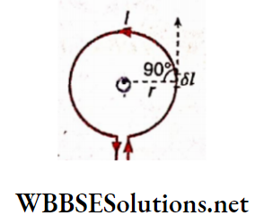
1. Magnetic field at the center of a circular conductor: Let the current through a circular conductor of radius r be I.
Due to an element of length δ1 of the conductor, the magnetic field at the center of a circle,
⇒ \(\delta B=\frac{\mu_0}{4 \pi} \cdot \frac{I \delta l \sin 90^{\circ}}{r^2}=\frac{\mu_0}{4 \pi} \cdot \frac{I \delta l}{r^2}\)
If the circumference of the circle is divided into a large number of such elements then, for each element, I and r remain the same and the angle between that element and the radius is 90°. Again sum of these elements = circumference of the circle = 2πr.
So, die magnetic field at the center of the circular conductor,
⇒ \(B=\frac{\mu_0}{4 \pi} \frac{I}{r^2} \sum \delta l=\frac{\mu_0}{4 \pi} \cdot \frac{I}{r^2} \cdot 2 \pi r=\frac{\mu_0 I}{2 r}\)…(1)
If the circular conductor of a single turn is replaced by a circular coil of N turns then,
⇒ \(B=\frac{\mu_0 N I}{2 r}\)….(2)
The direction magnetic field at the center of the circular conductor can be determined by the corkscrew rule. This direction is normally upward from the plane of the paper. If the conductor is in die form of a circular arc and if that arc makes an angle θ (rad) at the center, the magnetic field at the center of the circle
⇒ \(B=\frac{\mu_0 I}{2 r} \cdot \frac{\theta}{2 \pi}=\frac{\mu_0 I}{4 \pi r} \cdot \theta\)….(3)
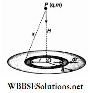
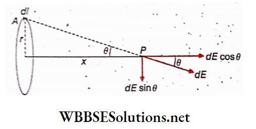
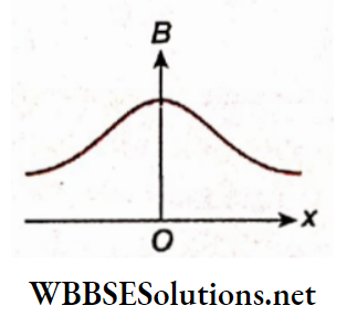
The magnetic field on the axis of a circular conductor:
Let r = radius of a circular conductor, I = current through the conductor, and O is the center of the circular conductor and hence. P is any point on the axis (OP – x). An element of length δl is considered at the topmost point C of the conductor. The line segment CP is perpendicular to this element So, for the element of length 8/ at C, the genetic field at the point P is,
⇒ \(\left.\delta B=\frac{\mu_0}{4 \pi} \cdot \frac{I \delta l \sin 90^{\circ}}{u^2}=\frac{\mu_0}{4 \pi} \cdot \frac{I \delta l}{u^2} \text { [here } C P=u\right]\)
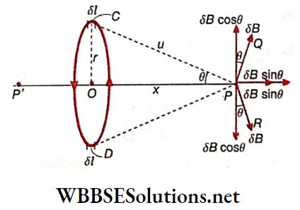
From the corkscrew rule, we see that the direction of δB is along PQ. The component of 8B along the axis is δBsinθ and perpendicular to the axis is δBcosθ. If an element of length δl is now considered at point D diametrically opposite to C on the circumference, the magnetic field at point P will be SB and its direction will be along PR. Naturally, its downward component δBcosθ neutralizes the previous component δBcosθ, but two components
δBsinθ each will be added together along the axis. In this way, if the whole circular conductor is considered, the algebraic sum of the components SBsinfl along the axis will be the resultant magnetic field due to the circular conductor at die point P.
∴ \(B=\sum \delta B \sin \theta=\frac{\mu_0}{4 \pi} \sum \frac{I \delta l}{u^2} \cdot \frac{r}{u}=\frac{\mu_0}{4 \pi} \sum \frac{I \delta l}{u^3} \cdot r\)
Now, due to the symmetry of the circular conductor, the magnitudes of I, r and u will be die same at every point on its circumference. Hence,
⇒ \(B=\frac{\mu_0}{4 \pi} \cdot \frac{I r}{u^3} \sum \delta l=\frac{\mu_0}{4 \pi} \cdot \frac{I r}{u^3} \cdot 2 \pi r=\frac{\mu_0 I}{2} \cdot \frac{r^2}{\left(u^2\right)^{3 / 2}}\)
So, \(B=\frac{\mu_0 I}{2} \cdot \frac{r^2}{\left(r^2+x^2\right)^{3 / 2}}\)….(4)
If a circular coil having N turns is taken instead of the circular conductor of single turn then,
⇒ \(B=\frac{\mu_0 N I}{2} \cdot \frac{r^2}{\left(r^2+x^2\right)^{3 / 2}}\)…..(5)
Now, at the center of the circle, i.e., at the point O, x = 0, and hence,
⇒ \(B=\frac{\mu_0 N l}{2 r}\), which is identical to the equation (2).
Expressions In COS or Gaussian system: In equations (1) to (5) above, substituting B→H, I→I, and μ0 → 4π we get,
magnetic intensity at the center of a circular conductor,.
⇒ \(H=\frac{2 \pi i}{r}\)
and magnetic intensity at the center of a circular coil having N-tums,
⇒ \(H=\frac{2 \pi N i}{r}\)
In the case of a conductor in the form of an arc of a circle, the magnetic intensity at the center of the conductor, H = \(\frac{i}{r}\)θ where θ is the angle made by the arc at the center.
Magnetic intensity at any point on the axis of a circular conductor,
⇒ \(H=2 \pi i \cdot \frac{r^2}{\left(r^2+x^2\right)^{3 / 2}}\)
In the case of a circular coil having N turns, the magnetic intensity at any point on its axis,
⇒ \(H=2 \pi N i \cdot \frac{r^2}{\left(r^2+x^2\right)^{3 / 2}}\)
Angle (θ) subtended by a current-carrying conductor of length 1 cm bent in the form of an arc of a circle of 1 cm radius is 1 rad. If the magnetic intensity at the center of the arc is 1 Oe, then substituting r = 1, θ = 1, H = 1 in the relation \(H=\frac{i \theta}{r}\), we get, i = 1.
Characteristics of the magnetic field of a circular conductor:
1. Direction of magnetic field: At any point on the axis of the conductor the direction of the resultant magnetic field is always along the axis. For the direction of current the magnetic field at the point P is along the axis and directed outward. But on the opposite side of the coil, at the point magnetic field is along the axis and directed inward, i.e., along Pf O. If the direction of current in the coil is reversed, at the point P magnetic field will be inward while at the point P’, it will be outward.
2. Magnitude of the magnetic field: From equation (5) we see that the magnitude of the field becomes maximum at the center of the circle, and decreases along the axis, on either side.
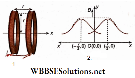
As a result, no uniform magnetic field is obtained at any point on the axis and thus a problem arises while constructing electrical instruments with a circular coil. This problem can be removed by using a Helmholtz double coil.
Helmholtz double coll: Two circular coils having the same radius (= r) are placed coaxially at a distance equal to their radius. If a direct current is passed through them in the same direction, the magnetic fields generated between them will have the same direction. Thus the resultant magnetic field remains almost uniform in between the coils.
Magnetic Effect Of Current And Magnetism
Electromagnetism Numerical Examples
Example 1. The radii of two concentric circular colls are 8 cm and 10 cm and the number of turns In them are 40 and 10, respectively. A 5A current Is passing through each of them in the same direction. Determine the magnetic field produced at the center of the two colls.
Solution:
Since current flows in the same direction through the two coils, the directions of magnetic fields at the center due to the coils will be the same. Hence, the resultant magnetic field will be obtained by adding these magnetic fields.
For the first coil, \(B_1=\frac{\mu_0 N_1 I}{2 r_1}\)
For the second coil, \(B_2=\frac{\mu_0 N_2 I}{2 r_2}\)
∴ The resultant magnetic field,
⇒ \(B=B_1+B_2=\frac{\mu_0 I}{2}\left(\frac{N_1}{r_1}+\frac{N_2}{r_2}\right)\)
⇒ \(\frac{4 \pi \times 10^{-7} \times 5}{2}\left(\frac{40}{8}+\frac{10}{10}\right)
\)
= 2π x 10-7 x 5 x 6
= 1.885 x 10⁻⁵ Wb.m-2
Example 2. A current I is flowing through an Infinitely long wire PQRS. The wire is bent a J S at right angles so that the part QR becomes one-fourth of the circumference of a circle of radius r whose center is at O. Determine the magnetic field at O.
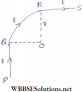
Solution:
With respect to point O, both the parts PQ and
RS are semi-infinite wires and hence, for each part magnetic field at point O will be,
⇒ \(B_1=B_2=\frac{\mu_0}{4 \pi} \cdot \frac{I}{r}\)
Again for a complete circular conductor, the magnetic field at its center = \(\frac{\mu_0 I}{2 r}\)
So. for the one-fourth part QR of the circle, the magnetic field
at O,
⇒ \(B_3=\frac{1}{4} \times \frac{\mu_0 I}{2 r}=\frac{\mu_0 I}{8 r}\)
Hence, the resultant magnetic field at O,
B = B1 + B2 + B3
⇒ \(\frac{\mu_0 I}{4 \pi r}+\frac{\mu_0 I}{4 \pi r}+\frac{\mu_0 I}{8 r}\)
⇒ \(\frac{\mu_0 I}{4 r}\left(\frac{1}{\pi}+\frac{1}{\pi}+\frac{1}{2}\right)=\frac{\mu_0(4+\pi) I}{8 \pi r}\)
Examples of Faraday’s Law of Induction
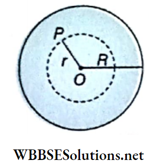
Example 3. Determine the magnetic field at point O due to the circuit.
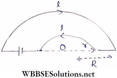
Solution:
Point O lies on the same straight line with the two linear parts of the circuit Hence, no magnetic field acts at O due to those two parts.
For a complete circular conductor, the magnetic field at the tire center of the circle = \(\frac{\mu_0 I}{2 r}\)
Hence, for a semicircular conductor, the magnetic field at the center = \(\frac{\mu_0 I}{4 r}\)
The magnetic field at O due to the semicircular conductor of radius r is \(B_1=\frac{\mu_0 I}{4 r}\) and that due to the semicircular conductor of radius \(R \text { is } B_2=\frac{\mu_0 I}{4 R}\).
The corkscrew rule shows that Bj and B2 are oppositely directed. Since Bj > Bz, the resultant magnetic field at the point O (upward with respect to the page of the book),
⇒ \(B=B_1-B_2=\frac{\mu_0 I}{4}\left(\frac{1}{r}-\frac{1}{R}\right)=\frac{\mu_0 I(R-r)}{4 r R}\)
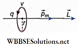
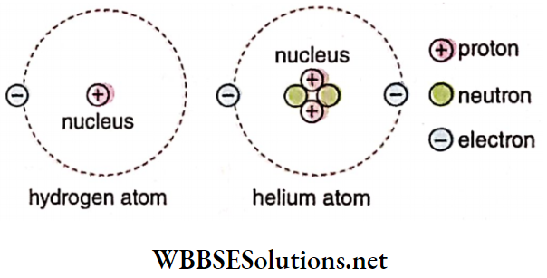
Example 4. What is the magnetic field produced at the center of a hydrogen atom due to the revolution of its electron in the first orbit (K-orbit)? The radius of the first orbit = 0.53 x 10⁻¹⁰ m, the velocity of the electron in that orbit = 2.19 x 10s m s-1
Solution:
Time period of revolution, \(T=\frac{2 \pi r}{v}\).
So, the circular loop formed due to the revolution of the electron carries an effective current
⇒ \(I=\frac{\text { charge }}{\text { time period }}=\frac{e}{T}=\frac{e v}{2 \pi r}\)
So, the magnetic field at the center of the atom,
⇒ \(B=\frac{\mu_0 I}{2 r}=\frac{\mu_0}{4 \pi} \cdot \frac{e v}{r^2}\)
⇒ \(10^{-7} \times \frac{\left(1.6 \times 10^{-19}\right) \times\left(2.19 \times 10^6\right)}{\left(0.53 \times 10^{-10}\right)^2}\)
= 12.47 T
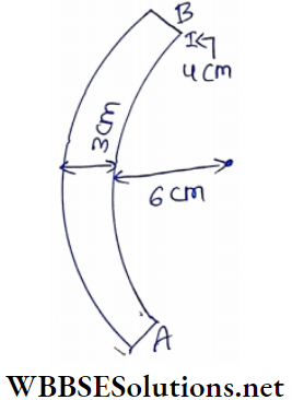
Example 5. Calculate the magnetic induction at point O (center of the partial circular conductor).
Solution:
Magnetic induction at die center due to whole conductor, B = Magnetic induction due to (straight part AB + curved part BCD + straight part DE)
∴ \(B_{\text {total }}=B_{A B}+B_{B C D}+B_{D E}\)
BAB = 0 [∵ thePoint O is along AB]
⇒ \(B_{B C D}=\frac{3}{4}\) of the ma8netic due to the whole circle
⇒ \(\frac{3}{4} \times \frac{\mu_0}{4 \pi} \cdot \frac{2 \pi I}{r}\) [directed inwards and perpendicular to the plane of the conductor]
⇒ \(B_{D E}=\frac{\mu_0}{4 \pi} \cdot \frac{I}{r}\) [directed outwards and perpendicular to the plane of the conductor]
∴ \(B_{\text {total }}=\frac{3}{4} \frac{\mu_0}{4 \pi} \frac{2 \pi l}{r}-\frac{\mu_0}{4 \pi} \frac{l}{r}\)
⇒ \(\frac{\mu_0}{4 \pi}, \frac{I}{r}\left[\frac{3}{2} \pi-1\right]\) [directed inwards and perpendicular to the plane of the conductor]
Example 6. Two concentric but mutually perpendicular conducting coils are carrying current 3 A and 4 A, respectively. If the radius of each coil is 2x cm, what will be the magnetic induction at the center of the coils? (μ0 = 4π x 10-7 Wb A-1.m-1)
Solution:
⇒ \(r=2 \pi \mathrm{cm}=\frac{\pi}{50} \mathrm{~m}\)
Magnetic field at the center of a circular coil, \(B=\frac{\mu_0 I}{2 r}\)
∴ For the first coil,
⇒ \(B_1=\frac{\left(4 \pi \times 10^{-7}\right) \times 3}{2 \times \frac{\pi}{50}}=3 \times 10^{-5} \mathrm{~Wb} \cdot \mathrm{m}^{-2}\)
and for the second coil,
⇒ \(B_2=\frac{\left(4 \pi \times 10^{-7}\right) \times 4}{\ddots 2 \times \frac{\pi}{50}}=4 \times 10^{-5} \mathrm{~Wb} \cdot \mathrm{m}^{-2}\)
Since the coils are mutually perpendicular, By and B2 are also at right angles to each other. Hence, the resultant magnetic field,
⇒ \(B=\sqrt{B_1^2+B_2^2}=\sqrt{(3)^2+(4)^2} \times 10^{-5}\)
= 5 x 10⁻⁵ Wb.m-2
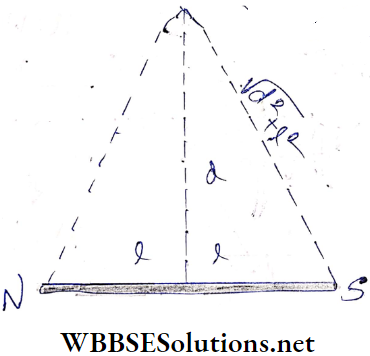
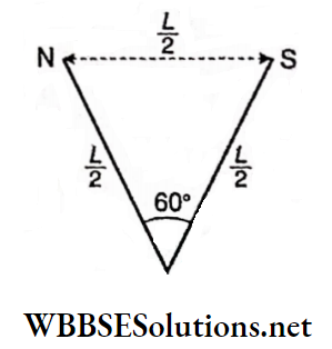
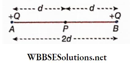
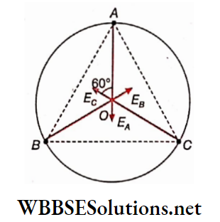
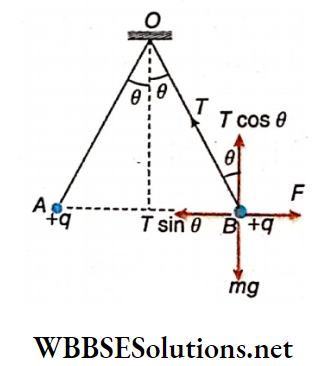
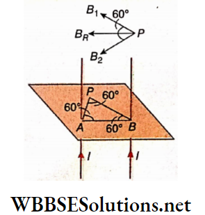
Example 7. Each of two long straight wires, passing through points A and B, carries a current directed vertically upwards with respect to the plane of the paper. The separation between them is r. Find out the magnetic field at a point P on that plane, which is at a distance r from each of the wires.
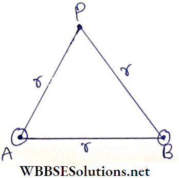
Solution:
Here PA = PB = r
Due to the current-carrying conductor, which passes through point A, the magnetic field intensity at P is,
⇒ \(B_1=\frac{\mu_0}{4 \pi} \frac{2 I}{P A}=\frac{\mu_0}{4 \pi} \frac{2 I}{r}\)
Similarly, due to the current-carrying conductor which passes through point B, the magnetic field intensity at point P is,
⇒ \(B_2=\frac{\mu_0}{4 \pi} \cdot \frac{2 I}{P B}=\frac{\mu_0}{4 \pi} \cdot \frac{2 I}{r} \text { (along } \overrightarrow{P B_2} \text { ) }\)
The resultant magnetic field intensity at point P is given by,
⇒ \(B=\sqrt{B_1^2+B_2^2+2 B_1 B_2 \cos 60^{\circ}}\)
⇒ \(\sqrt{\left(\frac{\mu_0}{4 \pi} \frac{2 I}{r}\right)^2\left[1^2+1^2+2 \cdot 1 \cdot 1 \cdot \frac{1}{2}\right]}\)
⇒ \(\frac{\mu_0}{4 \pi} \frac{2 I}{r} \sqrt{3} \text { (directed parallel to } \overrightarrow{B A} \text { ) }\)
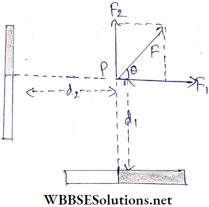
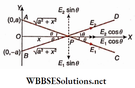
Example 8. Two small identical circular loops marked (1) and (2) carrying equal currents are placed with their geometrical axes perpendicular to each other. Find the magnitude and direction of the net magnetic field produced at O. Also determine the field when the radius of the loop is very large as compared to the distance of the point from the center.
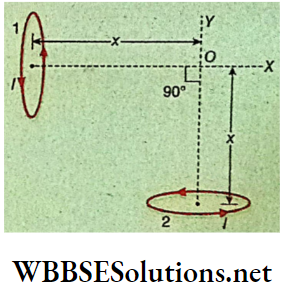
Solution:
Let R be the radius of each loop. Magnetic field at O due to loop 1,
⇒ \(B_1=\frac{\mu_0 I R^2}{2\left(R^2+x^2\right)^{3 / 2}} \text { (it acts along } \overrightarrow{O X} \text { ) }\)
Magnetic field at O due to loop 2,
⇒ \(B_2=\frac{\mu_0 I R^2}{2\left(R^2+x^2\right)^{3 / 2}} \text { (it acts along } \overrightarrow{O Y} \text { ) }\)
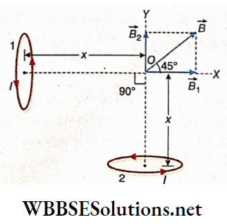
∴ The net magnetic field at O due to both the loops,
⇒ \(B=\sqrt{B_1^2+B_2^2}=\sqrt{2 B_1^2}=\sqrt{2} B_1 \cdot\left[∵ B_1=B_2\right]\)
⇒ \(=\sqrt{2} \frac{\mu_0 I R^2}{2\left(R^2+x^2\right)^{3 / 2}}=\frac{\mu_0 I R^2}{\sqrt{2}\left(R^2+x^2\right)^{3 / 2}}\)
This field acts at an angle of 45° with \(\vec{OX}\).
Now if R>>x, neglecting x2/R2 we get
⇒ \(B=\frac{\mu_0 I R^2}{\sqrt{2}\left[R^2\left(1+x^2 / R^2\right)\right]^{3 / 2}} \approx \frac{\mu_0 I R^2}{\sqrt{2} R^3}\)
∴ \(B \approx \frac{\mu_0 I}{\sqrt{2} R}\)
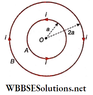
Example 9. Two circular coils of radii a and 2a having a common center, carry identical currents, but opposite directions. The number of turns of the second Conductor is 8. Show that magnetic field intensity at the center 3 times that glue to the smaller one. Also, find out the ChangeinWe previous result when current flows in the same direction throughout the coils
Solution:
Magnetic field intensity at the center O due to the smaller loop is,
⇒ \(B_1=\frac{\mu_0 i}{2 a} \text { (upwards) }\)
Similarly magnetic field intensity at the centre due to the bigger loop,
⇒ \(B_2=8 \times \frac{\mu_0 i}{2(2 a)}=\frac{2 \mu_0 i}{a}\) (downwards)
∴ The net magnetic field at O,
B = B2-B1
⇒ \(\frac{\mu_0 i}{a}\left(2-\frac{1}{2}\right)\)
⇒ \(\frac{3 \mu_0 i}{2 a}=3 B_1 \quad\left[∵ B_1=\frac{\mu_0 i}{2 a}\right]\)
Hence resultant field is 3 times that due to the smaller loop.
Now if the direction of the current is the same for both loops, the resultant field will be,
⇒ \(B=B_1+B_2=\frac{\mu_0 i}{2 a}+\frac{2 \mu_0 i}{a}=5 \frac{\mu_0 i}{2 a}=5 B_1\)
Hence the resultant field will be 5 times that due to the smaller loop if current flows in the same direction.
Example 10. A wire loop is formed by joining two semicircular wires of radii r1 and r2. If the loop carries a current I, find the magnetic field at the center O.
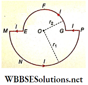
Solution:
The magnetic field at the point O due to the semicircular part MNP is,
⇒ \(\dot{B}_{M N P}=\frac{\mu_0}{4} \cdot \frac{I}{r_1} \text { (upwards) }\)
Similarly magnetic field at O due to the semicircular part GFE is,
⇒ \(B_{G F E}=\frac{\mu_0}{4} \cdot \frac{I}{r_2} \text { (upwards) }\)
As the point, O lies along the straight parts ME and PG of the loop, the magnetic field due to them at O is zero.
The so-net magnetic field at O due to the whole loop,
B = B1 + B2
⇒ \(\frac{\mu_0}{4} \cdot \frac{I}{r_1}+\frac{\mu_0}{4} \cdot \frac{I}{r_2}\)
∴ \(B=\frac{\mu_0}{4} I\left[\frac{1}{r_1}+\frac{1}{r_2}\right] \text { (upwards) }\)
Example 11. The radius and number of turns of a circular coil are 10 cm and 25 respectively. What should be the current through the coil that will produce a magnetic field of 6.28 x 10⁻⁵Wb.m-2 at its center?
Solution:
Radius of the coil, r = \(\frac{10}{2}\) = 5cm = 0.05m;
number of turns, N = 25, and magnetic field at the center of the coil
B = 6.28 x 10⁻⁵Wb.m-2.
Now, \(B=\frac{\mu_0 N I}{2 r}\)
∴ \(I=\frac{2 r B}{\mu_0 r}=\frac{2 \times 0.05 \times\left(6.28 \times 10^{-5}\right)}{\left(4 \times \pi \times 10^{-7}\right) \times 25}\)
= 0.2A
Example 12. The magnetic field due to a current carrying a circular loop of radius 3 cm at a point on the axis at a distance of 4 cm from the center is 54μT. What will be Its value at the center of the loop?
Solution:
Magnetic field on the axis of a circular conductor; \(B=\frac{\mu_0 I}{2} \frac{r^2}{\left(r^2+x^2\right)^{3 / 2}}\) and magnetic field at the centre (x = 0) is
⇒ \(B^{\prime}=\frac{\mu_0 I}{2 r}\)
∴ \(\frac{B^{\prime}}{B}=\frac{\left(r^2+x^2\right)^{3 / 2}}{r^3}\)
or, \(B^{\prime}=\frac{\left(r^2+x^2\right)^{3 / 2}}{r^3} B\)
⇒ \(\frac{\left(3^2+4^2\right)^{3 / 2}}{3^3} \times 54\)
∴ \(B^{\prime}=250 \mu \mathrm{T}\)
Magnetic Effect Of Current And Magnetism
Electromagnetism Ampere’s Circuital Law
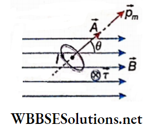
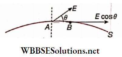
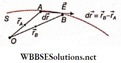
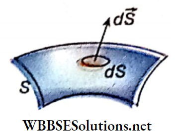
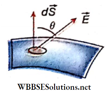
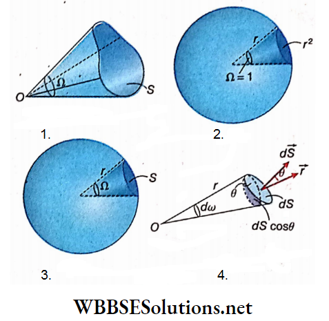
Line integral or path integral of a vector: Let \(\vec{A}\) be a vector and 81 a very small line segment. This segment can be treated as a vector \(\delta \vec{l}\), where the magnitude of \(\delta \vec{l}\) is equal to the length of the segment and its direction is along the tangent to that segment. (\(\delta \vec{l}\) is shown in a magnified form),
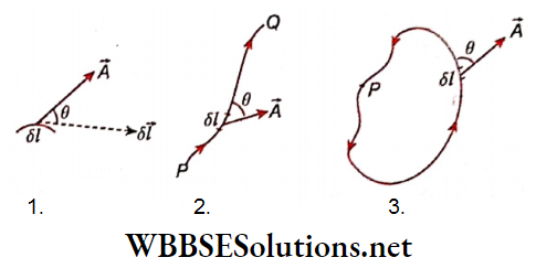
Now, \(\vec{A} \cdot \delta \vec{l}=A \delta l \cos \theta\)
The sum of the above dot products along a finite line segment PQ can be expressed as an integral (using the symbol dl, instead of δl).
⇒ \(\lim _{n \rightarrow \infty} \sum_{i=1}^n \vec{A} \cdot \delta \vec{l}_i=\int_P^Q \vec{A} \cdot d \vec{l}=\int_P^Q A \cos \theta d l\)
It is called the line integral or path integral of vector \(\vec{A}\) along the path PQ. It is to be noted that the magnitude of vector \(\vec{A}\) may vary between point A to point B and if the direction of \(\vec{A}\) changes, θ will also change. The determination of the magnitude of a line integral is in general very complicated. However, due to different types of symmetry, the integral can often be determined easily.
Closed line integral:
A path that closes on itself is a closed path. To express the line integral of a vector along a closed path the symbol \(\oint\) is used.
For Example, the line integral of the vector \(\vec{A}\), called the circulation of \(\vec{A}\), is given by
⇒ \(\oint \vec{A} \cdot d \vec{l}=\oint A \cos \theta d l\)
Example:
The line integral of force vector work done:
If the force vector \(\vec{F}\) is taken as a special Example of vector \(\vec{A}\), according to the definition of work done we can write, work done by the force \(\vec{F}\) for displacement \(\overline{\delta l}\)
⇒ \(d W=\vec{F} \cdot \delta \vec{l}=F \delta l \cos \theta\)
So, tire total work done along the segment PQ.
⇒ \(W=\int_P^Q d W=\int_P^Q \vec{F} \cdot d \vec{l}=\int_P^Q F \cos \theta d l\)
Similarly, total work done by the force \(\vec{F}\) along a closed path,
⇒ \(W=\oint \vec{F} \cdot d \vec{l}=\oint F \cos \theta d l\)
If the force is conservative, the work done is zero. Naturally, the physical significance of the line integral of the force vector is this integral always indicates tire work done along a line.
Similarly, line integrals of different vectors in physics have different physical significances. For Example, the liter integral of tire electrostatic field \(\vec{E}\) around a closed path is zero because the electrostatic field is a conservation force field.
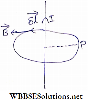
Statement of Ampere’s circuital law: The line integral of the magnetic field vector along a closed path in any magnetic field is equal to the product of the net current enclosed by the closed path and the permeability of vacuum, i.e.,
⇒ \(\oint \vec{B} \cdot d \vec{l}=\mu_0 I\)….(1)
Here, I = net current enclosed by the closed path.
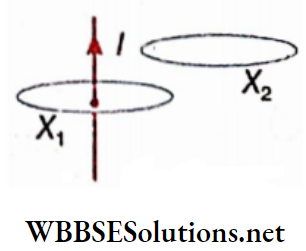
Explanation:
If Ω is the closed path, it encloses current I, and as a result,
⇒ \(\oint_{X_1} \vec{B} \cdot d \vec{l}=\mu_0 I\)
On the other hand, if we consider the closed path X2, it encloses no current and henceI = 0.
⇒ \(\oint_{X_2} \vec{B} \cdot d \vec{l}\)
2. If any closed path encloses a number of conductors, carrying currents in different directions, the algebraic sum of the enclosed currents is to be taken.
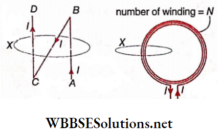
Currents in the parts AB, BC, and CD may be taken as I, -I, and I, respectively, and for the closed path X we can write,
⇒ \(\oint_X \vec{B} \cdot d \vec{l}=\mu_0(I-l+l)=\mu_0 l\)
Again, since an equal current, I flow through each of Tiro’s turns,
⇒ \(\oint_X \vec{B} \cdot d \vec{l}=\mu_0 N I \quad[N=\text { number of turns }]\)
CGS form of the law: Substituting B→H, I→i and μ0 → 4π we can write,
for a closed path enclosing a single turn
⇒ \(\oint \vec{H} \cdot d \vec{l}=4 \pi i\)
and for a closed path enclosing N turns,
⇒ \(\oint \vec{H} \cdot d \vec{l}=4 \pi N i\)
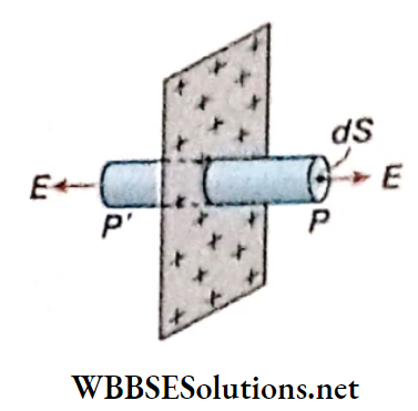
Application of Ampere’s Circuital Law:
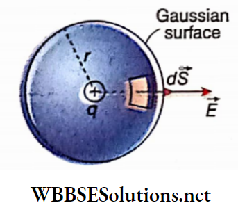
The magnetic field of a long straight wire:
Let a current I flow through a straight long conductor. We have to determine the magnetic field at the point P at a perpendicular distance r from the wire.
Taking the wire as an axis, a circular path is drawn through the point P having radius r in such a manner that the tire path lies in a plane perpendicular to the wire.
It is convenient to consider this circular path as Ampere’s closed path. For an element of length \(\delta \vec{l}\) on this closed path, the corkscrew rule shows that the magnetic field \(\vec{B}\) is parallel to \(\delta \vec{l}\) at every place, i.e., the angle between them is 0°.
Again, due to symmetry, the magnitude of \(\vec{B} \text { (i.e., }|\vec{B}|=B \text { ) }\) is the same at every point on the closed path.
So, \(\oint \vec{B} \cdot d \vec{l}=\oint_{B d l \cos \theta}\)
Since the current enclosedÿ by the closed path is I, from Ampere’s circuital law,
B – 2πr = μ0I
or, \(B=\frac{\mu_0 I}{2 \pi r}=\frac{\mu_0}{4 \pi} \cdot \frac{2 I}{r}\)
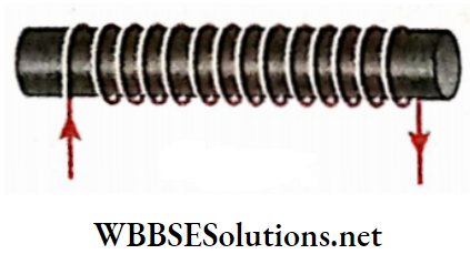
Solenoid: If a long insulated conducting wire is wound tightly over the surface of a cylinder so that every circular turn is perpendicular to the axis of the cylinder, then this coll is called a solenoid.
The axis of the cylinder is the axis of the solenoid. Usually after making a solenoid the inner cylinder is removed. (A conductor with a coating of insulating material is called an insulated conductor.)
Magnetic lines of force: The solenoid is placed on a cardboard with its axis lying on the cardboard plane. Now some light iron filings are scattered over the cardboard and the cardboard is slightly tapped.
The iron filings arrange themselves along the magnetic lines of force. The magnetic lines of force.
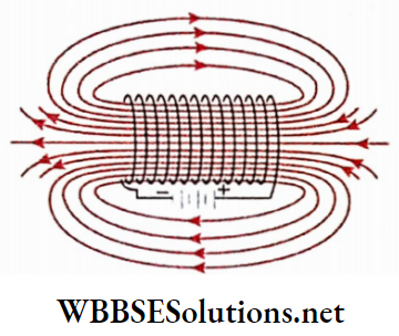
Characteristics of the lines of force: The number density of magnetic lines of force inside the solenoid is very high, i.e., the magnetic field in that part is very strong.
The magnetic field outside the solenoid can be neglected in comparison. Moreover, the magnetic lines of force inside the solenoid are parallel to its axis. So, a strong and nearly uniform axial magnetic field is generated inside the solenoid
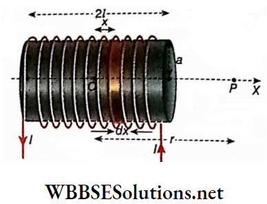
Magnetic field inside a long straight solenoid: Let the length of a long straight solenoid = L and its number of turns =N.
So, the number of turns per unit length of the solenoid, n = \(\frac{N}{L}\)A few number of turns of the solenoid is shown. Current through the solenoid = I.
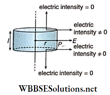
Here, the rectangle abed is taken as the Ampere’s closed path whose side ab=L lies along the axis of the solenoid.
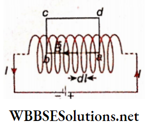
Let N be the number of turns enclosed by the rectangular path, \(\overrightarrow{d l}\) is a very small segment on this path, and \(\vec{B}\) is the magnetic field produced due to this part of the solenoid. According to Ampere’s circuital law,
⇒ \(\begin{array}{r} \oint_{a b c d} \vec{B} \cdot d \vec{l}=\int_a^b \vec{B} \cdot d \vec{l}+\int_b^c \vec{B} \cdot \overrightarrow{d l}+\int_c^d \vec{B} \cdot \overrightarrow{d l} \\ +\int_d^a \vec{B} \cdot d \vec{l}=\mu_0 N I \end{array}\) …(1)
As \(d \vec{l} \text { and } \vec{B}\) are in the same direction along ab so,
⇒ \(\int_a^b \vec{B} \cdot d \vec{l}=\int_a^b B d l \cos 0^{\circ}=B \int_a^b d l=B L\)….(2)
On the other hand, the magnetic field \(\vec{B}\) is perpendicular to the small segments \(d \vec{l}\) on the parts of me and da inside the solenoid. As the solenoid is an ideal one, \(\vec{B}\) = 0 for the side cd and also \(\vec{B}\) = 0 for the parts of me and da which are outside the solenoid.
Hence from equations (1) and (2) we get,
⇒ \(\oint_{a b c d} \vec{B} \cdot d \vec{l}=B L=\mu_0 N I\)…(3)
or, \(B=\mu_0 \frac{N}{L} \cdot I \quad \text { or, } B=\mu_0 n I\)….(4)
It is to be noted here that the magnitude of the magnetic field depends on the number of turns per unit length n but not on the total number of turns N of the solenoid. Hence, to increase the magnetic field it is not sufficient to increase the number of turns but it is also necessary to make the turns very close to each other so that the value of n increases.
CGS expression: Substituting B→H, I→I, and μ0 → 4π in equation (4), we get, H = 4πni.
Toroid: A toroid is a long insulated conducting wire, wound on a donut-shaped core having a circular axis and uniform cross-section so that each turn is normal to the axis.
A toroid is nothing but a solenoid bent to close on itself. A long straight solenoid has two definite ends but a toroid is an endless solenoid.
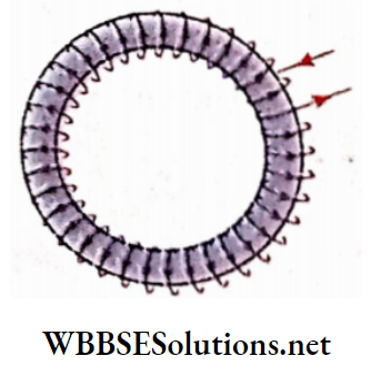
The magnetic field of a toroid: Let the radius of the ring of a toroid = r and the total number of turns in it = N. Sd,’ the circumference of the circular axis of the toroid = 2nr, arid the number of turns per unit length of it, \(n=\frac{N}{2 \pi r}\). A few turns of a toroid are shown. Current through the toroid = I.
Here, the axis of the toroid is considered as the Ampere’s closed path. If any small part \(8 \vec{l}\) is taken on the axis, according to the corkscrew rule, the direction of the magnetic field \(\vec{B}\) is parallel to \(8 \vec{l}\) at every point, i.e., the angle between them is 0°. Now, due to symmetry, the magnitude of \(\vec{B}\) is the same at all points on the axis.
Hence,
⇒ \(\oint \vec{B} \cdot d \vec{l}=\oint B d l \cos 0^{\circ}=B \oint d l=B \cdot 2 \pi r\)
Again, the net current enclosed by the axis = current I through each of N turns = NI
So, according to Ampere’s circuital law,
⇒ \(B \cdot 2 \pi r=\mu_0 N I \quad \text { or, } B=\mu_0 \cdot \frac{N}{2 \pi r} I\)
or, B = μ0nI….(5)
It should be noted that equation (5) is identical to equation (4). From this, it is concluded that if a solenoid is too long, whatever may be the shape, the magnitude of the magnetic field at any point on its axis will be B = μ0nI.
CGS expression: Substituting B→H, I→i, and μ0 → 4π in equation (5), we get, H = 4πni.
The core of a solenoid: In the above discussion, air is considered the core of a solenoid or a toroid. Thus, magnetic permeability is taken as μ0. For any other core (like iron, nickel, etc.), the value of the magnetic permeability changes notably. In that case, Ampere’s circuital law takes the form
⇒ \(\oint \vec{B} \cdot d \vec{l}=\mu n I, \text { where } \mu\), is the permeability of the core.
Limitation of Ampere’s circuital law:
Maxwell proved that Ampere’s circuital law is valid only for steady current. If the enclosed current varies with time, on the right-hand side of equation (1), an additional term should be added.
By this correction, Maxwell arrived at his famous electromagnetic field equations. An elaborate discussion about it has been done in the chapter on Electromagnetic waves. We should remember that, Ampere’s law is not incorrect, it can only be called incomplete.
In our discussion, we consider the cases where electric current remains steady with time, and hence, the equations obtained from Ampere’s law are accurate.
Magnetic Effect Of Current And Magnetism
Electromagnetism Numerical Examples
Example 1. A solenoid with 7 turns per unit length Is carrying a current of 2.5 A. What is the magnetic Intensity Inside the solenoid?
Solution:
Turns per unit length, n = 7 cm-1 =700 m-1; if μ is the permeability of the medium inside the solenoid then, magnetic field B = μnl.
∴ Magnetic intensity,
H = \(\frac{B}{\mu}\) = nI
=700 x 2.5
= 1750 A m-1
Example 2. The length of a solenoid is GO cm and Its total number of turns is 1250. If 2 A current is passed through It, what will be the magnetic field at any point on Its axis?
Solution:
Number of turns = 1250, length = 60 cm = 0.6 m
∴ Number of turns per unit length, n = \(\frac{1250}{0.6}\) m-1
So, the magnetic field at any point on its axis,
B = μ0nI
= 4π x 10-7 x \(\frac{1250}{0.6}\) x 2 [μ0 = 47T x 10-7Wb.A-1 m-1]
= 5.23 x 10⁻³ Wb/m2
Example 3. Two solenoids made of insulated conducting wires and of equal lengths are such that one is wound over another. The resistance of each of them is R and the number of turns per unit length is n. The solenoids are now connected in
- Series
- Parallel and the combination Is then connected with a battery of emf E.
- If current flows through them in the same direction in both cases, determine the magnetic field along the axis of the solenoids in each case
Solution:
1. In case of series combination, equivalent resistance =2R and hence current through each solenoid, \(I_s=\frac{E}{2 R}\)
Hence, the resultant magnetic field along the axis,
⇒ \(B=B_1+B_2=\mu_0 n I_s+\mu_0 n I_s\)
⇒ \(2 \mu_0 n \cdot \frac{E}{2 R}=\frac{\mu_0 n E}{R}\)
in the case of parallel combination, the terminal potential difference across each solenoid = E.
So, current through each solenoid, Ip = \(\frac{E}{R}\).
⇒ \(B=B_1+B_2=\mu_0 n I_p+\mu_0 n I_p\)
⇒ \(2 \mu_0 n \cdot \frac{E}{R}=\frac{2 \mu_0 n E}{R}\)
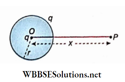
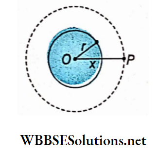
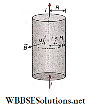
Example 4. A long straight solid conductor of radius 5 cm carries a current of 2 A, which is uniformly distributed over its circular cross-section. Find the magnetic field at a distance of 3 cm from the axis of the conductor.
Solution:
Let us consider an internal point P at a distance r(= 3 cm) from the axis of the conductor. Imagine a circular path of radius r around the conductor, such that P lies on it. If R is the radius of the solid conductor then the current enclosed by the circular path,
⇒ \(I_1=\frac{I}{\pi R^2} \times \pi r^2=\frac{I r^2}{R^2}\)
Let B be the magnetic field at point P due to the current-carrying conductor. B acts tangentially to the circular path. So according to Ampere’s Circuital law,
⇒ \(\oint \vec{B} \cdot d \vec{l}=\mu_0 I_1\)
or, \(B \times 2 \pi r=\frac{\mu_0 I r^2}{R^2}\)
Here, I = 2 A, r = 3 cm = 0.03 m, R = 5 cm = 0.05 m
∴ \(B=\frac{10^{-7} \times 2 \times 2 \times 0.03}{(0.05)^2}=4.8 \times 10^{-6} \mathrm{~T}\)
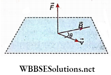
Force on A Moving Charge In A Magnetic Field
Let \(\vec{B}\) = magnetic field at a point, q= electric charge of a particle, \(\vec{v}\) = velocity of the particle at the given point.
Magnetic force on the charged particle due to the magnetic field at that point,
⇒ \(\vec{F}=q \vec{v} \times \vec{B}\) ….(1)
If the angle between \(\vec{v} \text { and } \vec{B} \text { be } \theta\), from the cross product of two vectors,
⇒ \(F=|\vec{F}|=q \nu B \sin \theta\)…(2)
Naturally, if v = 0, F = 0, i.e., if a charged particle is at rest then no magnetic force acts on it.
Definition of magnetic field \(\vec{B}{/latex]:
Direction of [latex]\vec{B}{/latex]: If θ = 0° or 0 = 180°, F = 0. Thus no magnetic force acts on a charged particle that is moving parallel or antiparallel to the magnetic field. Hence, in a magnetic field, the direction (or its opposite direction) of a moving charged particle for which no magnetic force acts on it, defines the direction of [latex]\vec{B}{/latex].
Magnitude of [latex]\vec{B}{/latex]: If v and B remain perpendicular to each other, d = 90°. Thus, the magnitude of the magnetic force [latex]\vec{F}{/latex] becomes maximum. Expressing this maximum force by Fm, equation (2) can be written as,
⇒ [latex]F_m=q v B\)…(3)
If q = 1 and v – 1, then B = Fm. The maximum possible force exerted by a magnetic field on a particle of unit charge moving with unit velocity through the field defines this magnitude of the magnetic field.
Unit of B: From equation (3), \([B]=\frac{[F]}{[q][v]}\)
Hence the unit of B is,
⇒ \(\frac{\mathrm{N}}{\mathrm{A} \cdot \mathrm{s} \cdot\left(\mathrm{m} \cdot \mathrm{s}^{-1}\right)} \quad \text { or } \mathrm{N} \cdot \mathrm{A}^{-1} \cdot \mathrm{m}^{-1}\)
This unit is known as tesla (T) or Weber/metre2 (Wb.m”2).
Electromagnetism Notes For Class 12 WBCHSE Significance of the cross product:
Applying the rule of the cross product of two vectors in equation (1) we can conclude that \(\vec{F}\) is always perpendicular to the plane containing \(\vec{v} \text { and } \vec{B}\).
If a right-handed corkscrew rotated from the direction of \(\vec{v} \text { to } \vec{B}\), the direction of advancement of the screw-head indicates the direction of \(\vec{F}\).
Work done by the magnetic force is zero: \(\vec{F} \text { and } \vec{v}\) is always perpendicular to each other. Since the displacement of a particle is taken along the direction of its velocity, at any point in the magnetic field, the force \(\vec{F}\) and a small displacement \(\vec{ds}\) of the particle are perpendicular to each other. Then, for the magnetic force F and its displacement \(\vec{ds}\), work done,
⇒ \(d W=\vec{F} \cdot d \vec{s}=F d s \cos 90^{\circ}=0\)
Hence, the work done by the magnetic force on a moving charged particle in a magnetic field is zero. In other words, the magnetic force is a no-work force.
Again, we know that, work done on a free particle = change in the kinetic energy of the particle. Since magnetic force is a no-work force, the kinetic energy of a charged particle is not affected.
∴ AK = W =0
or, \(\frac{1}{2}\) mv2 = constant (m = mass of the particle)
or, v = constant
So, when a magnetic force acts on a charged particle moving in a magnetic field, its speed as well as its kinetic energy remains unaffected.
Magnetic force In CGS system: in this system, charge q is expressed in esu [see the chapter: ‘Electric Fields’]. But to indicate the magnetic force, the current as well as the charge must be measured in emu.
1 emu of charge = 3 x 10¹⁰ esu of charge = c esu [ c = velocity of light in vacuum = 3 x 1010 cm.s-1 ]
So, if the magnitude of an electric charge is q esu, in the electromagnetic unit, it will be \(\vec{q}{c}\) emu.
Hence, the above-mentioned SI equation (1) can be expressed in
CGS system as,
⇒ \(\vec{F}=\frac{q}{c} \vec{v} \times \vec{B}\)
In this equation, magnetic field \(\vec{B}\) is used but not the magnetic intensity \(\vec{H}\). Here c = 3 x 1010 cm.s-1. F, q, v, and B are measured in dyn, esu, cm.s-1, and gauss or G, respectively.
Note that, 1 C = 0.1 emu of charge = 3 x 10⁹ esu of charge.
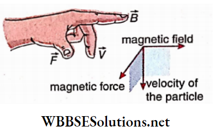
Fleming’s left-hand rule: If a charged particle moves at right angles to the magnetic field, is if the angle between \(\vec{v}\) and \(\vec{B}\) be θ = 90°, then from it can be concluded that the three vectors \(\vec{v}, \vec{B} \text { and } \vec{F}\) are mutually perpendicular. This special case can be easily explained by Fleming’s left-hand rule.
Path of a Moving Charge in a Uniform Magnetic Field:
Uniform magnetic field: A magnetic field is said to be uniform if its magnitude and direction remain constant in a region. We know that a magnetic field is represented by magnetic lines of force. For a uniform magnetic field
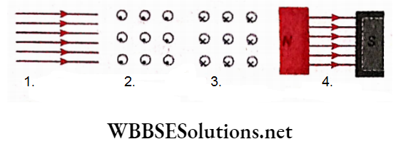
Magnetic lines of force are parallel to each other because the direction of the magnetic field remains constant;
The magnitude of the magnetic field also remains unchanged and hence the number density of the lines of force at different points are equal, i.e., the lines of force are equispaced.
Moreover, to represent a uniform normal and upward magnetic field with respect to the plane of the page; equispaced marked points are used; on the other hand, to denote a downward uniform magnetic field similar marked points are used
In the region adjacent to the surface, the terrestrial magnetic field is assumed to be formed. Only in the vicinity of magnets or magnetic materials, are these lines of force distorted a little.
A uniform magnetic field is also generated between two strong opposite magnetic poles kept very close to each other.
Determination of the path of a charged partake: The charged particle is at rest: Since \(\vec{F}=q \vec{v} \times \vec{B}\) if \(\vec{v}\) = 0, \(\vec{F}\) = 0. Hence, in this case, no magnetic force acts on the particle and the charged particle remains at rest.
The charged particle enters with a velocity \(\vec{v}\) parallel to the magnetic field: If the velocity of the particle and the magnetic field are parallel to each other, then \(\vec{v} \times \vec{B}=0\). So, the magnetic force, \(\vec{F}=q \vec{v} \times \vec{B}=0\). Since no magnetic force acts in this case, the particle continues to move along a straight line.
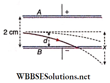
The charged particle enters with a velocity \(\vec{v}\) perpendicular to the magnetic field:
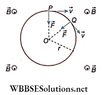
Let a uniform magnetic field B be acting upward, perpendicular to the plane of the paper. A particle having charge +q enters that magnetic field at P with a velocity \(\vec{v}\) parallel to the plane of the paper.
Applying cross product rule, we see that the magnetic force \(\vec{F}\) ing on the particle will be normal to \(\vec{v}\) and along the direction \(\vec{PO}\).
As a result, the particle will be accelerated towards \(\vec{PO}\), and hence it will tend to deviate from its path.
When the particle reaches another point Q, the magnetic force \(\vec{F}\) will still act normally to \(\vec{v}\) and along \(\vec{QO}\).
In this way, magnetic force acting on the charged particle at every point of its path is always directed towards point O.
This force acts as a centripetal force on the particle, which therefore keeps revolving along a circular path centered at O and of radius r (r = PO = QO). Since the magnitude of velocity does not change under the influence of the magnetic field, the charged particle will have a uniform circular motion.
The radius of the circular path: Magnetic force, \(\vec{F}=q \vec{v} \times \vec{B}\).
Since the angle between v and B is 90°, the magnitude of the magnetic force,
⇒ \(F=|\vec{F}|=q v B \sin 90^{\circ}=q v B\)
If the mass of the charged particle is m,
⇒ \(\text { centripetal force }=\frac{m v^2}{r}\)
So, \(q v B=\frac{m v^2}{r} \quad
or, [latex]r=\frac{m v}{q B}\)…(1)
We see from the equation (1) that:
For a given charged particle (q = constant) and for a definite magnetic field (B = constant), the radius of the circular path is directly proportional to the momentum (mv) of the particle. This property is utilized in the measurement of the mass of a charged particle in a mass spectroscope.
If a given charged particle (q = constant) enters a magnetic field with a definite momentum (mv= constant) then the radius of the circular path is inversely proportional to the applied magnetic field (B).
The radius of the circular path is inversely proportional to its specific charge \(\frac{q}{m}\). For Example, the charge of a proton and electron is the same but the mass of a proton is 1836 times that of an electron.
Hence, the value of \(\frac{q}{m}\) for an electron is 1836 times higher. It means that if a proton and an electron enter a magnetic field with equal velocity, the electron revolves in a circular path of a much smaller radius.
It is clear that if the charge is -q instead of +q, the direction of uniform circular motion will be reversed.
Period of resolution and cyclotron frequency: Circumference of the circular path =2πr.
Since it is a uniform circular Otiort, time period,
⇒ \(T=\frac{2 \pi r}{\nu}=2 \pi \frac{\dot{m}}{q B}\)…(2)
The number of complete revolutions made in unit time, i.e., frequency of the circular motion,
⇒ \(n=\frac{1}{T}=\frac{1}{2 \pi}\left(\frac{q}{m}\right) B\) ….(3)
This frequency n is called cyclotron frequency.
Evidently, both T and n are independent of the radius of the path as well as of the velocity. From equation (1), it is clear that \(frac{r}{v}\) = constant. This property for the motion of a charged particle in a magnetic field is utilized in particle accelerators like cyclotrons.
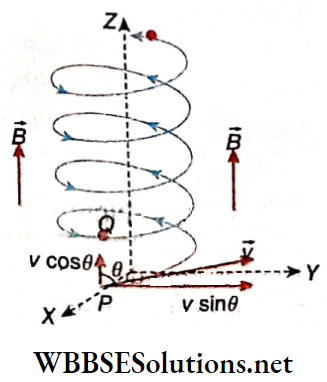
The charged particle enters the magnetic field at an inclined path: Let the z-axis be chosen along the direction of a uniform magnetic field acting at a place. A particle of charge +q and mass m enters that magnetic field with velocity \(\vec{v}\) at the point P on the xy -plane.
If this velocity \(\vec{v}\) is inclined at an angle θ with the magnetic field \(\vec{B}\), the component of velocity along \(\vec{B}\), i.e., along z-axis = vcosθ and the component of velocity perpendicular to B, i.e., on the xy -plane = vsinθ.
Naturally, no magnetic force acts on the particle the component cost, and hence this corÿonent remains unchanged. So, the charged particle performs a uniform linear motion along the magnetic field.
Again, the component vsinθ produces a uniform circular motion. The radius o|this uniform circular motion can be obtained by using for v in equation (1),
⇒ \(r=\frac{m v \sin \theta}{q B}\)….(4)
The time period and frequency of the particle in uniform circular motion do not depend on the velocity of the particle; hence just like equations. (2) and (3), it can be written as
⇒ \(T=\frac{2 \pi m}{q B} \text { and } n=\frac{1}{T}=\frac{q B}{2 \pi m}\)….(5)
Due to the combination of linear motion parallel to the z-axis and uniform circular motion on the xy-plane, the charged particle follows a spiral or helical path.
The axis of this helical path is the z-axis. For each complete revolution of the particle, the distance covered along the z-axis, i.e., along the direction of the magnetic field is called the pitch of this helical motion.
So, pitch = time period x linear velocity
⇒ \(\frac{2 \pi m}{q B} \cdot v \cos \theta\)
⇒ \(\frac{2 \pi m}{q B} \cdot \frac{q B r}{m \sin \theta} \cdot \cos \theta\)
= 2πrcotθ
= circumference of the circular path x cotθ …(6)
The property of the helical motion of a charged particle in a magnetic field is utilized in the magnetic focussing of different equipment.
WBCHSE Class 12 Physics Chapter 6 solutions Cyclotron:
The cyclotron was developed in 1932 by Professor E O Lawrence at the BerkelyInstitute, taliformia is a powerful particle accelerator for accelerating positively charged particles such as protons, aaa particles, etc., to very high energies so that they can be used in disintegration experiments.
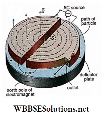
Description: It consists of two cylindrical shells of copper having semicircular cross sections with the same diameter and height. They are open towards their diameter and all other sides are closed.
The diameters of the two shells are much larger than their heights. They are arranged side by side in such a way that a small gap exists between their diameters. Each is called ‘dee’ on account of its shape like the letter D.
Two pole pieces of a strong electromagnet are placed above and below the dees in such a way that a uniform magnetic field -defects perpendicular to the plane of the dees.
An alternating potential of the order of 105 V and of high frequency (about 106 Hz) is applied between the dees. So the dees act as the two electrodes -of the source of potential.
An ion source S is located near the center of the dees and it supplies the positive ions to be accelerated. At the periphery of the dees, an auxiliary negative electrode deflects the accelerated ions onto the target to be bombarded.
The whole space inside the dee is evacuated to a pressure of about 10-6 mm of mercury. If the ‘whole arrangement is seen horizontally.
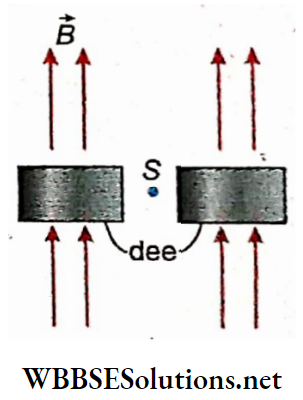
Principle of action: Suppose that a positive ion (e.g., hydrogen ion H+ or helium ion He++ ) emerges from the ion sources S. Generally these ions are produced by bombarding gas molecules with high-velocity electrons.
The positive ion produced at S will be attracted to whichever dee happens to be negative at that moment. Due to this attractive force-velocity of the ion increases and it enters the dee. Inside the dee, there is no electric field.
Owing to the magnetic field which is perpendicular to the plane of the dee the ion describes a semicircular path. The radius of the path is obtained from equation (1) of the section.
The ion moves in this path at a constant speed. At the end of the semicircular path when the ion arrives at the gap between the dees, then the other dee should become negative. Then the ion is again attracted, its velocity increases and it enters the other dee. From equation
It is understood that due, to the increase of velocity v, the radius r of the semicircular path will also increase. But from the equation
Of section, it is seen that in spite of the increase in velocity and radius, the time taken to describe each of the semicircular paths remains the same.
In this way, then at last reaches the outer edge of the dee and comes out with a high velocity. To increase the velocity of the ion, the magnetic field (\(\vec{B}\)) may be increased
Resonance condition: It is obvious that the condition of proper operation of a cyclotron is that the time taken by the ion to traverse a semicircular path will be equal to half of the time period of the alternating potential. So the frequency of the applied alternating potential difference n0 must be equal to the frequency of revolution of the ion, i.e., cyclotron frequency n.
⇒ \(\frac{1}{2 \pi}\left(\frac{q}{m}\right) B=n_0\)….(1)
This equation is called the resonance condition of the cyclotron. In practice, the value of n0 is kept fixed and the magnetic field B is varied until the above condition is satisfied.
The kinetic energy of the accelerated particle: If v is the velocity of a charged particle of mass m and charge q and if it moves perpendicular to a magnetic field B, the radius of its circular path according to the equation (1) of the section is,
⇒ \(r=\frac{m v}{q B} \quad\)
or, \(v=\frac{q B r}{m}\)
If R is the radius of a dee of the cyclotron, then the velocity of the charged particle ejected from the outlet is given by,
⇒ \(v_0=\frac{q B R}{m}\)
So, the kinetic energy of, the particle,
⇒ \(E=\frac{1}{2} m \nu_0^2=\frac{q^2 B^2 R^2}{2 m}\)….(2)
The kinetic energy of the accelerated particle Disadvantages:
1. If the velocity of the charged particle is high enough to be displacement comparable to the velocity of light, the mass of the particle does not remain constant.
According to the theory of relativity, m increases with the increase of velocity. So the resonance condition according to equation (1) is violated and the cyclotron does not function.
For an electron, the relativistic increase of mass is much greater. So the electrons very quickly get out of step. Hence a cyclotron is not used for accelerating electrons.
2. To make the charged particle sufficiently fast, dees of very large diameter are to be taken. This diameter may even exceed 100m. The construction of an electromagnet of so large diameter is prohibitively expensive and technically complicated.
WBCHSE Class 12 Physics Chapter 6 solutions Remedies:
1. With the increase of mass due to relativity the frequency n0 of the alternating source may also be diminished in such a way that the product mn0 always remains constant. In that case, the resonance condition is never violated. The machine with this arrangement is called a synchro-cyclotron.
2. Both B and n0 can be changed simultaneously in such a way that
- The resonance condition is always satisfied
- In spite of the increase in velocity of the charged particle, the radius r of its circular path remains unchanged. So a thin annular electromagnet of that radius will serve the purpose. Hence technical complications and expenses may be reduced sufficiently. This machine is called a synchrotron.
Path of a Charged Particle in a Uniform Electric Field:
If a particle of charge +q experiences a force \(\vec{F}\) in a uniform electric field, from definition,
the electric field, \(\vec{E}=\frac{\vec{F}}{q} \quad \text { i.e., } \vec{F}=q \vec{E}\)…(1)
If the mass of the particle is m, then acceleration,
⇒ \(\vec{a}=\frac{\vec{F}}{m}=\frac{q \vec{E}}{m}\)….(2)
Naturally, for negative charges, the acceleration (\(\vec{a}\)) will be opposite to \(\vec{E}\). Due to this acceleration, the charged particle acquires different kinds of motion in different cases.
1. The charged particle is initially at rest: Initial velocity u = o. Hence, after time t,
the velocity of the particle, \(v=a t=\frac{q E}{m} t\)
and displacement, \(s=\frac{1}{2} a t^2=\frac{q E}{2 m} t^2\)
2. The charged particle enters with a velocity \(\vec{u}\) along the electric held: Since the direction, of acceleration, is in the direction of \(\vec{E}\) after time t,
velocity of the particle, \(v=u+\frac{q E}{m} t\)
and the displacement, \(s=u t+\frac{1}{2} \frac{q E}{m} t^2\)
3. The charged particle enters with a velocity \(\vec{u}\) perpendicular to the electric field: Let the uniform electric field act parallel to the y-axis and the charged particle enters this electric field with a velocity \(\vec{u}\) at the point P along the x-axis
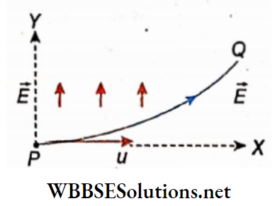
There is no component of E along the x-axis and hence the particle has no acceleration in this direction. So, along the x-axis, the particle possesses a uniform velocity u.
If the distance covered by the particle in time t is x, then t = \(\frac{x}{u}\). Again, along y-axis, initial velocity of the particle = 0, but acceleration, a = \(\frac{qE}{m}\).
So, in time t, displacement of the particle along the y-axis is,
⇒ \(y=\frac{1}{2} a t^2=\frac{1}{2} \frac{q E}{m}\left(\frac{x}{u}\right)^2=\frac{q E}{2 m u^2} \cdot x^2\)
or, \(x^2=\frac{2 m u^2}{q E} y\)….(3)
This is an equation of a parabola (in the form of x² = 4ay)
So, the path of the particle will be parabolic.
Path of Charged Particle in Crossed Electric Field and Magnetic Field:
Let a particle of charge +q and mass m enter an electromagnetic field at the point O along the z-axis with a velocity \(\vec{v}\),
Electric field \(\vec{E}\) at that point O is along the x-axis and magnetic field \(\vec{B}\) is along the y-axis, i.e.,\(\vec{v}\) \(\vec{E}\) and \(\vec{B}\) are mutually perpendicular. Now, the electric force acting on the particle along the x-axis = qE. The magnetic force acting on the particle = qvB, and the cross-product rule shows that this magnetic force acts along the negative direction of the x-axis.
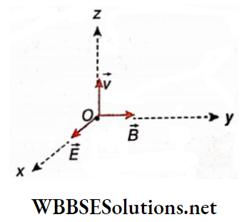
So, here the electric and the magnetic fields are oppositely directed. Keeping the directions of i, and B unchanged, if these two forces are made equal in magnitude, the net force acting on the charged particle becomes zero. In this case, the charged particle continues its motion along the z-axis with its initial Velocity v without suffering any deviation. The condition for this situation is,
⇒ \(q E=q v B \quad \text { or, } \quad \nu=\frac{E}{B}\)
Suppose the electric field E and magnetic field \(\vec{B}\) are acting simultaneously perpendicular to each other.
Let a stream of charged particles enter the space in a direction perpendicular to both \(\vec{E}\) and \(\vec{B}\). If the speed of the charged particles is different, then only those particles whose speed is equal to the ratio \(\frac{E}{B}\) will pass through the hole S on the screen without any deflection.
All other particles will be deflected from, their path and will not reach point S. This arrangement is known as a velocity filter. In the figure only the green particle would pass through the hole S as its velocity is equal to \(\frac{E}{B}\).
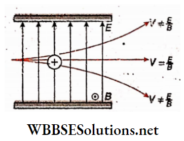
This principle, known as the velocity selector, Is utilized In the determination of Q specific charge \(\frac{q}{m}\) of an electron by J J Thomson’s experiment and θ mass of the nucleus with the help of mass-spectrometer.
Lorentz Force:
In an electromagnetic field, if a charge q enters with velocity \(\vec{v}\), the forces acting on it are
Electric force, \(\vec{F}_e=q \vec{E} \quad[\vec{E}=\text { electric field }]\)
Magnetic force, \(\vec{F}_m=q \vec{v} \times \vec{B} \quad[\vec{B}=\text { magnetic field }]\)
These forces, \(\vec{F}_e \text { and } \vec{F}_m\) are called Lorentz electric force and Lorentz magnetic force, respectively. The resultant Lorentz
force acting on the particle (charge),
⇒ \(\vec{F}=\vec{F}_e+\vec{F}_m=q \vec{E}+q \vec{v} \times \vec{B}\) – q (\(\vec{F}\) x \(\vec{v}\) x \(\vec{B}\))….(1)
In CGS or Gaussian system:
⇒ \(\vec{F}_{e q}=q \vec{E}, \vec{F}_m=\frac{q}{c}(\vec{v} \times \vec{B})\)
So, the resultant Lorentz force, \(\vec{F}=q\left[\vec{E}+\frac{1}{c}(\vec{v} \times \vec{B})\right]\)
Remarks:
1. If the charged particle is at rest in an electromagnetic field, an electric force still acts on it, but as [lavec]\vec{v}[/latex] = 0 no magnetic, force acts.
2. For negatively charged particles (e.g., electron or negative ion) q is replaced by -q, and hence the direct|on of each force \(\left(\vec{F}_e \vec{F}_m \text { and } \vec{F}\right)\) will be reversed.
WBCHSE Class 12 Physics Chapter 6 Solutions
Electromagnetism Numerical Examples
Example 1. An amagnetic field of 0.4 T is applied on a proton moving with a velocity of 5 x 10⁻⁶ m s-1. The magnetic field acts at an angle of 30º with the direction of velocity of the proton. What will be the acceleration of the proton? (mass ofa proton = 1.6.x 10-27 kg)
Solution:
Force acting on the proton, F= qvBsinθ.
∴ Acceleration antiproton = \(\frac{\text { force acting }}{\text { mass of proton }}=\frac{q v B \sin \theta}{m}\)
Here, q = 1.6 x 10⁻¹⁹ C, v = 5 x 10⁶ m.s-1,
B = 0.40 T, θ = 30° and m = 1.6 x 10⁻²⁷ kg.
∴ Acceleration of the proton
⇒ \(\frac{1.6 \times 10^{-19} \times 5 \times 10^6 \times 0.40 \times \sin 30^{\circ}}{1.6 \times 10^{-27}}\)
= 1014 m.s-2
Example 2. An electron (mass = 9 x 10-31g, charge = 1.6 x 10⁻¹⁹ C) enters a magnetic field with a velocity of 106 m si and starts rotating in a circular path of radius 10 cm. What is the value of the magnetic field?
Solution:
The electron is rotating in a circular path i.e. the direction Of the velocity of the electron is perpendicular to the direction of the magnetic field. So the magnetic force = qvB, which provides the necessary centripetal force for the circular motion.
∴ \(q v B=\frac{m v^2}{r}\) [r = radius of the circular path = 10cm = 0.1 m]
or, \(B=\frac{m v}{q r}=\frac{\left(9 \times 10^{-31}\right) \times 10^6}{\left(2.6 \times 10^{-19}\right) \times 0.1}\)
= 5.6 x 10⁻⁵ T
Example 3. Two particles of equal charge are accelerated by applying the same potential difference and then allowed to enter a uniform magnetic field normally. If the particles keep revolving along circular paths of radii R1 and R2, determine the ratio of their masses
Solution:
If the charge of each particle is q and the potential difference applied is V, kinetic energy acquired = qV
So, \(q V=\frac{1}{2} m_1 v_1^2=\frac{1}{2} m_2 v_2^2\)
or, \(\frac{v_1}{v_2}=\sqrt{\frac{m_2}{m_1}}\)
Again, the magnetic force required to revolve along a circular path = centripetal force.
∴ For the first particle,
⇒ \(q v_1 B=\frac{m_1 v_1^2}{R_1} \quad\)
or, \(q B=\frac{m_1 v_1}{R_1}\)
For the second particle, \(q B=\frac{m_2 v_2}{R_2}\)
∴ \(\frac{m_1 v_1}{R_1}=\frac{m_2 v_2}{R_2} \quad\)
or, \(\frac{m_1}{m_2}, \frac{v_1}{v_2}=\frac{R_1}{R_2}\)
or, \(\frac{m_1}{m_2} \cdot \sqrt{\frac{m_2}{m_1}}=\frac{R_1}{R_2} \quad\)
or, \(\sqrt{\frac{m_1}{m_2}}=\frac{R_1}{R_2}\)
or, \(\frac{m_1}{m_2}=\left(\frac{R_1}{R_2}\right)^2\)
Example 4. In a cyclotron, the frequency of alternating current is 12 MHz and the radius of its dee is 0.53 m.
- What should be the operating magnetic field to accelerate protons?
- What is the kinetic energy of the proton beam produced by the cyclotron? Given, the mass of the proton = 1.67 x 10⁻²⁷ kg and charge = +1.6 X 10⁻¹⁹ C.
Solution:
1. Condition of resonance,
⇒ \(\frac{1}{2 \pi}\left(\frac{q}{m}\right) B=n_0 \quad \text { or, } B=\frac{2 \pi n_0 m}{q}\)
Here, n0 = 12 MHz = 12 x 106 Hz = 12 x 106 s-1
So, \(B=\frac{2 \times 3.14 \times\left(12 \times 10^6\right) \times\left(1.67 \times 10^{-27}\right)}{1.6 \times 10^{-19}}\)
= 0.79 Wb.m-2
2. Kinetic energy of proton,
⇒ \(E^{\prime}=\frac{q^2 B^2 R^2}{2 m}\)
= \(\frac{\left(1.6 \times 10^{-19}\right)^2 \times(0.79)^2 \times(0.53)^2}{2 \times\left(1.67 \times 10^{-27}\right)}\)
= \(1.34 \times 10^{-12} \mathrm{~J}\)
= \(\frac{1.34 \times 10^{-12}}{1.6 \times 10^{-19}} \mathrm{eV}\)
= 8375 x 10-6 eV
= 8.375 MeV
Example 5. A beam of protons with velocity 4 x 10 sm.s-1 enters a uniform magnetic field of 0.4 T at an angle of 60° to the magnetic field. Find the radius of the helical path of the proton beam and the time period of revolution. Also, find the pitch of the helix. Mass of proton = 1.67 X 10⁻²⁷ Vg
Solution:
Mass of the proton, m = 1.67 x 10⁻²⁷ kg velocity of the proton, v = 4 x 10⁵ m.s-1; charge, q = 1.6 x 1049 C.
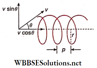
∵ The component of velocity perpendicular to the field is vsinθ, the radius of the helical path,
⇒ \(r=\frac{m \nu \sin \theta}{q B}\)
= \(\frac{\left(1.67 \times 10^{-27}\right)\left(4 \times 10^5\right) \sqrt{3}}{\left(1.6 \times 10^{-19}\right) \times 0.4 \times 2}\)
= 9 x 10⁻³ m
= 0.9 cm
During the time period of the revolution,
⇒ \(T=\frac{2 \pi r}{\nu \sin \theta}\)
= \(\frac{2 \times 3.14 \times 0.009 \times 2}{4 \times 10^5 \times \sqrt{3}}\)
= 1.63 x 10⁻⁷ s
The pitch of the helix,
p = vcosθ x T =4 x 10⁵ x \(\frac{1}{2}\) x 1.63 x 10-7
= 3.26 x 10⁻² m
= 3.26 cm
Class 12 WBCHSE Physics Electromagnetism Concepts
Electromagnetism Action Of A Magnet On Current
Oersted’s experiment deals with the influence of a current-carrying conductor on a magnet. The magnet, in reaction, also exerts equal but opposite force on the current-carrying conductor.
So, it is possible to move a current-carrying wire in a magnetic field. This kind of motion is very important for practical purposes. This phenomenon is the subject matter of electrodynamics.
Force on a Current-Carrying Conductor in a Magnetic Field:
The Lorentz force acting on a charge q moving with velocity \(\vec{v}\) in a magnetic field \(\vec{B}\) is,
⇒ \(\vec{F}=q \vec{v} \times \vec{B}\)
When current flows in a circuit, the drift motion of free electric charges through the circuit is considered as the cause of that current. Naturally, the magnetic force acting on those free charges in a magnetic field acts as the force on the current-carrying conductor.
Let the current through a circuit = I; a V element of length \(\vec{dl}\) of that circuit is considered.
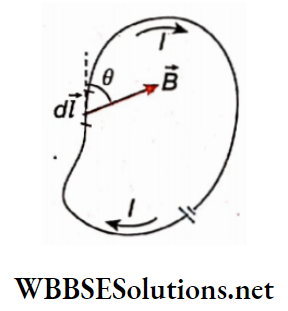
The magnetic field at the position of this element of the circuit = \(\vec{B}\). If dq amount of charge crosses dl length in time dt, current the circuit, \(I=\frac{d q}{d t}\)
Velocity of the charge, \(\vec{v}=\frac{d \vec{l}}{d t}\)
So, the magnetic force acting on the small part \(\vec{dl}\)
⇒ \(d \vec{F}=d q \vec{v} \times \vec{B}=d q \cdot \frac{d l}{d t} \times \vec{B}=\frac{d q}{d t} d \vec{l} \times \vec{B}\)
∴ \(d \vec{F}=I d \vec{l} \times \vec{B}\) ….(1)
If the angle between \(d \vec{l} \text { and } \vec{B}\) be θ, then
\(dF=|d \vec{F}|=I d l B \sin \theta=B I d l \sin \theta\)….(2)
So, the magnetic force acting on the whole circuit or on a finite part of it,
⇒ \(F=\int d F=\int B I d l \sin \theta\)…(3)
Generally, for different elements- of the circuit, both B and θ may change. Hence, in the absence of some special symmetry, the integral of equation (3) becomes very complicated.
Special cases:
The current carrying wire is at right angles with a uniform magnetic field: For any small part of the wire, θ = 90° or sinθ = 1. If the magnetic field is uniform, B = constant. If a current carrying wire of length is placed in this uniform magnetic field, according to equation (3) the force acting on the wire will be,
F = BIl….(4)
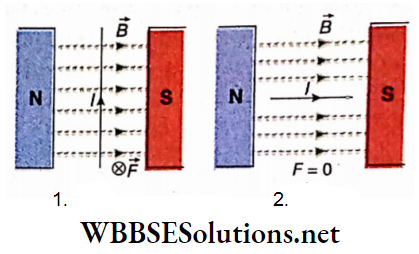
The current-carrying wire is placed parallel to the magnetic field: For any small part of the wire, 0 = 0° or sinθ = 0.
So, according to equation (3), the force acting on the wire is,
F = 0….(5)
Note that, the units of l or dl, I, B, and F are m, A, Wb.m-2, and N, respectively.
Fleming’s left-hand rule:
If a long straight current-carrying conductor is kept at right angles with a uniform magnetic field, i.e., if for each element of the wire, the angle between \(\vec{dl}\) and \(\vec{B}\) is θ = 90°, then according to the rule of cross-product we can say from equation (1) that the three vectors \(\vec{dl}\), \(\vec{B}\) and \(\vec{dF}\) will be mutually perpendicular.
Fleming’s left-hand rule is a handy tool for determining the direction of the magnetic force acting on a current-carrying conductor, perpendicular to the magnetic field.
Statement: If the forefinger, middle finger, and thumb of the left hand are stretched mutually perpendicular to each other, such that the forefinger points to the direction of the magnetic field and the middle finger points to the direction of current, then the thumb points to the direction of force experienced by the conductor.
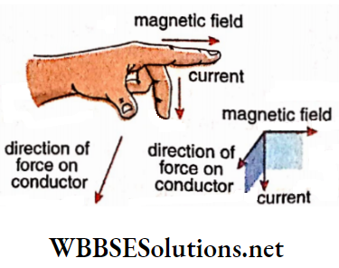
This left-hand rule is also known as the motor rule.
Barlow’s wheel: We can demonstrate the action of a magnet on an electric current with the help of this experimental arrangement.
Description: B is the Barlow’s wheel made of a thin copper plate having a number of sharp teeth. The wheel B is kept vertical such that its one sharp tooth remains in contact with mercury kept in a container placed in between two poles of a strong horse-shoe magnet (NS). Now the wheel and the mercury inside the container (M) are connected to a source of current E.
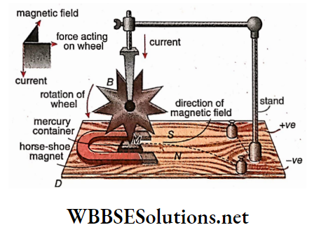
Working principle: The magnetic field acts from the JV-pole to the S-pole of the magnet parallel to the horizontal platform.
Since the tooth of the wheel remains in contact with mercury, the circuit is closed as soon as the battery is switched on. As a result, the current flows in a downward direction.
From Fleming’s left-hand rule, we see that a magnetic force acts on the current toward the right. Due to this force, the tooth will be deflected towards the right. As a result, the circuit breaks.
Hence magnetic force will no longer act on the wheel. But due to inertia of motion, the next tooth comes in contact with mercury and in a similar way will be deflected towards the right. Hence, a continuous anticlockwise motion will be observed in Barlow’s wheel.
Electromagnetism Derivations For Class 12 WBCHSE Discussions:
1. To get an effective result, the wheel should be very light. Moreover, the magnetic field and the electric current should be very strong.
2. If the direction of either the magnetic field or the electric current is reversed, the rotation of the wheel will also be reversed; but if both of them are reversed then the rotation of the wheel will be in the same direction.
3. The machine which converts electrical energy into rotational energy (usually mechanical energy) is called a motor. So, Barlow’s wheel is a motor, although it has no practical use.
Torque on a Current Loop in a Uniform Magnetic Field:
PQRS is a rectangular conductor. Its length, PQ = RS =l and breadth, QR = PS = b
So, the area of the rectangular face of the conductor, <A= Tb. This rectangular conductor is placed in a magnetic field B in such a way that
- PQ and RS 316 perpendicular to the magnetic field
- The surface PQRS is parallel to the magnetic field.
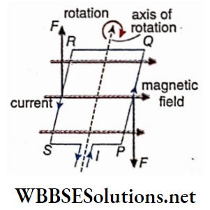
If a current is sent through the conductor,
1. No force acts on the arms QR and PS as they are parallel to the magnetic field,
2. Magnitude of the force (\(\vec{F}\)) acting on each of the arms PQ and RS, F = BIl.
Applying Fleming’s left-hand rule, we see that these two equal forces are downward and upward, respectively and hence they constitute a couple.
Since the perpendicular distance between these two forces is QR = PS = b, the moment of the couple, i.e., the torque acting on the coil is,
⇒ \(\tau=B I l \cdot b=B I A\)….(1)
and due to this torque, the coil starts to rotate. Instead of a single turn, if the conducting coil has N turns, torque acting on it,
⇒ \(\tau\) = BNIA….(2)
Equations (1) and (2) show that the torque r depends only on area A of the coil. This means that the shape of the coil is not important. Instead of a rectangular coil, a coil of any other shape of equal area may be used to obtain the same torque.
Vector representation of torque: We know that any plane surface can be treated as a vector, such that the magnitude of the vector is equal to the magnitude of its area and its direction is along the normal to that plane.
So, the quantity A in equation (1) can be expressed as a vector \(\vec{A}\) the direct arbitrary position of the rotating loop under the influence of torque. If the angle between \(\vec{A}\) and the magnetic field \(\vec{B}\) is θ, from equation (1) we get,
⇒ \(\tau=B I A \sin \theta\)….(3)
The vector representation of the above equation is,
⇒ \(\vec{\tau}=I \vec{A} \times \vec{B}\)…..(4)
So, the torque acting on a conducting coil having N turns will be
⇒ \(\vec{\tau}=N I \vec{A} \times \vec{B}\)….(5)
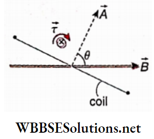
Electromagnetism Derivations For Class 12 WBCHSE
Electromagnetism Numerical Examples
Example 1. 2A current is flowing through a circular coil of radius 10 cm, made of insulated wire and having 100 turns.
- If the circular plane of the conductor is kept at right angles to the direction of a magnetic field of 0.2 Wb.m-2, determine the force acting on the coil.
- If the conductor is placed parallel to the magnetic field, determine the torque acting on it.
Solution:
Here,N = 100, r = 10 cm = 0.1 m,
B = 0.2 Wb m-2.
∴ Circumference of the circular loop,
L = 2πr
= 2 x I x 0.1
= 0.628 m
Area of the circular loop,
A = πr2 = π x (0.1)2
= 0.0314 m2
1. The whole circumference of the conductor is normal to the magnetic field; hence magnetic force
= NILB
= 100 x 2 x 0.628 x 0.2
= 25.12 N
[It should be noted that, in this situation, if the circular plane is taken as a vector, its direction will be perpendicular to that plane, i.e., parallel to the magnetic field. As a result, no torque will act on the conductor.]
2. If the circular plane is taken as a vector, its direction will be perpendicular to the plane, i.e., normal to the magnetic field.
As a result, the torque acting on the conductor
= NIAB
= 100 x 2 x 0.0314 x 0.2
= 1.256 N.m
Example 2. The radius of a circular coil having 100 turns Is 5 cm and a current of 0.5 A is flowing through this coil. If it is placed in a uniform magnetic field of strength 0.001 T, then what torque will act on the coil when the plane of the coil is
- Parallel to the magnetic field
- Inclined at 30° with the magnetic field
- Perpendicular to the magnetic field?
Solution:
Number of turns = 100
Current, I = 0.5A
Radius of the circular coil, r = 5 cm = 5 x 10⁻²m
∴ Area of the coil, A = πr2 = 3.14 x (5 x 10-2)2m2
Magnetic field intensity, B = 0.0001 T
Now torque acting on the current carrying coil due to magnetic field,
⇒ \(\tau=n B I A \sin \theta\)
1. When the coil is parallel to the malefic field, then θ = 90°
So, \(\tau=n B I A \sin 90^{\circ}\)
= 100 x 0.001 x 0.5 x 3.14 x 25 x 10-4
= 3.93 x 10⁻⁴ N.m
2. When the coil makes an angle 30° with the field, then θ = 60°
So, \(\tau=n B I A \sin 60^{\circ}\)
⇒ \(=100 \times 0.001 \times 0.5 \times 3.14 \times 25 \times 10^{-4} \times \frac{\sqrt{3}}{2}\)
= 3.4 X 10⁻⁴ N.m
3. When the coil is perpendicular to the field, θ = 0°.
∵ \(\tau=0\)
Example 3. On a smooth plane inclined at 30° with the horizontal, a thin current-carrying metallic rod is placed parallel to the horizontal ground. The plane is In a uniform magnetic field of 0.15 T along the vertical direction. For what value of current can the rod remain stationary? The mass per unit length of the rod is 0.30kg/m.
Solution:
Along the inclined plane, the component of the magnetic force acting on the conductor and the component of the weight of the conductor will bring equilibrium. So,
BIlcosd = mgsinθ….(1)
Here, force on the conductor BIl acts horizontally towards the right.
Now, from equation (1),
⇒ \(I=\frac{m g \sin \theta}{B l \cos \theta}=\frac{m g}{B l} \tan \theta\)
∵ \(\frac{m}{l}=0.30 \mathrm{~kg} / \mathrm{m}, g=9.8 \mathrm{~m} / \mathrm{s}^2\)
B = 0.15 T, θ = 30°
∴ \(I=\frac{0.30 \times 9.8}{0.15} \tan 30^{\circ}\)
⇒ \(=2 \times 9.8 \times \frac{1}{\sqrt{3}}=11.3 \mathrm{~A}\)
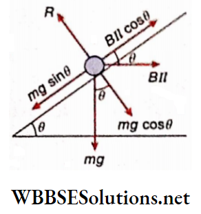
Electromagnetism Action Of Current On Current
Like parallel currents: Let two straight parallel conductors PQ and RS be kept horizontally and I1 and I2 be the currents flowing through them in the same direction
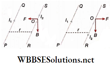
According to the corkscrew rule, for current I1, the magnetic field B at any point O on the wire RS will act downwards. If Fleming’s left-hand rule is applied at point O on wire RS, it is seen that the wire RS will experience a force F towards the wire PQ.
As Reactiion, the wire PQ also will experience the same force F towards the wire RS. So, we can conclude that two parallel currents attract each other.
Unlike parallel currents: Suppose I1 and I2 currents are flowing through the wires PQ and RS, respectively mutually opposite directions. Applying Fleming’s left-hand rule similarly, it is found that the wire RS experiences a force F away from the wire PQ. The wire PQ also experiences an equal but opposite force that acts on It away from the wire RS. So, we can conclude that two unlike parallel currents repel each other.
The magnitude of the force of attraction or repulsion: Let r be the perpendicular distance between two long, straight parallel conductors kept in a vacuum or air.
Due to current I1 the magnetic field at a distance of r will be
⇒ \(B=\frac{\mu_0}{4 \pi} \cdot \frac{2 I_1}{r}\)
From the relation F = BIl, we get, the force acting on the unit length of the wire placed at r, carrying current I2, which is
⇒ \(\left.F=\frac{\mu_0}{4 \pi} \cdot \frac{2 I_1 I_2}{r} \text { [Putting } B=\frac{\mu_0}{4 \pi} \cdot \frac{2 I_1}{r} \text { and } l=I_2\right]\)….(1)
Here, the unit of r is m, I1, and I2 is A, F is N.m-1, and μ0 = 4π x 10-7 H.m-1.
This equation gives the definition of international ampere. If I1 = I2 = 1 A and r = 1 m,
⇒ \(F=\frac{\mu_0}{4 \pi} \times \frac{2 \times 1 \times 1}{1}=\frac{4 \pi \times 10^{-7}}{4 \pi} \times 2\)
= 2 x 10⁻⁷ N
1 ampere: Two long straight parallel conducting wires, having negligible cross sections and carrying equal currents are kept 1 m apart from each other. The steady direct current for which each wire experiences a force of 2 x 10⁻⁷ N per unit length, is called 1 ampere.
Expressions in Gaussian system: Substituting \(I_1 \rightarrow i_1, I_2 \rightarrow i_2 \text { and } \mu_0 \rightarrow 4 \pi\) in equation (1) we get,
⇒ \(F=\frac{2 i_1 i_2}{r}\)
Here unit of r is cm, F is dyn, and i1 and i2 emu
Obliquo currents:
1. If currents through two oblique straight conductors lying in the same plane converge to or diverge from their point of intersection, they attract each other
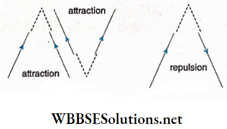
2. If currents through two oblique straight conductors lying in the same plane are such that, one of them is directed towards and the other directed away from their point of intersection, they repel each other.
Experimental Demonstration Roget’s Vibrating Spiral:
Description: A long elastic spring made of insulated copper wire is suspended from a rigid support. A small spherical copper bob, attached at the lower end of the spring, just touches the mercury kept in a vessel. The fulcrum at the upper end of the spring and mercury in the vessel are joined to a battery.
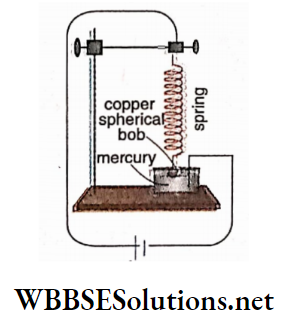
Working principle: When the battery is switched on, a unidirectional parallel current flows through the turns of the spring and hence the turns attract each other, resulting in the contraction of the spring.
Naturally, the copper bob remains no longer in contact with mercury and hence the circuit is cut off. As soon as the bob leaves the surface of the mercury, the attraction between the turns of the spring no longer exists.
Hence, the spring elongates due to its own weight, the copper sphere touches the mercury again and closes the circuit. In this way, alternate compression and elongation of the spring goes on and hence the spring vibrates continuously.
This experiment proves that a number of unidirectional parallel currents attract each other.
Electromagnetism Numerical Examples
Example 1. Two very long- conducting wires are kept at a distance of 4 cm from each other in a vacuum. Currents flowing through the wires are 25A and 5A, respectively. Find the length of each conductor, which experiences a force of 125 dynes.
Solution:
Here, I1 = 25 A, I2 = 5 A, r = 4 cm = 0.04 m
So, the force acting per unit length of the wire,
⇒ \(F=F=\frac{\mu_0}{4 \pi} \cdot \frac{2 I_1 I_2}{r}=\frac{4 \pi \times 10^{-7}}{4 \pi} \cdot \frac{2 \times 25 \times 5}{0.04}\)
= 625 x 10-6 N.m-5
For 125 dyn or 125 x 10-5 N force, the effective length of each wire,
⇒ \(l=\frac{125 \times 10^{-5}}{625 \times 10^{-6}}=2 \mathrm{~m}\)
Example 2. Two long straight parallel conducting wires kept 0.5 m apart, carry 1 A and 3 A currents, respectively.
- What is the force acting per unit length of tire two wires?
- At what position in the plane of the wires, the resultant magnetic field will be zero?
Solution:
1. Force acting per unit length,
⇒ \(F=\frac{\mu_0}{4 \pi} \cdot \frac{2 I_1 I_2}{r}=10^{-7} \times \frac{2 \times 1 \times 3}{0.5}\)
= 1.2 x 10⁻⁶ N.m-1
According to the corkscrew rule, the magnetic fields produced between two wires are mutually opposite in direction. Let any point P in this region be at a distance x from the first wire.
∴ The magnetic field at point P due to the first wire
⇒ \(\frac{\mu_0}{4 \pi} \cdot \frac{2 I_1}{x}\)
and magnetic field at the point P due to the second wire
⇒ \(\frac{\mu_0}{4 \pi} \cdot \frac{2 I_2}{(0.5-x)}\)
If the resultant magnetic field at the point P is zero, then
⇒ \(\frac{\mu_0}{4 \pi} \cdot \frac{2 I_1}{x}=\frac{\mu_0}{4 \pi} \cdot \frac{2 I_2}{(0.5-x)} \quad\)
or, \(\frac{0.5-x}{x}=\frac{I_2}{I_1}=\frac{3}{1}\)
or, 3x = 0.5 – x
or, 4x = 0.5
or, x = \(\frac{0.5}{4}\)
= 0.125 m
So, at any point on the plane between the wires, 0.125 m away from the first wire, the resultant magnetic field will be zero
Example 3. Two long parallel conductors, kept at a distance d, carry currents I1 and I2, respectively. The mutual force acting between them. Now, the current one is doubled and its direction is also reversed. If the distance of separation between them is made 3d, what will be the force acting between the two conductors?
Solution:
For the unit length of the conductors,
⇒ \(F=\frac{\mu_0}{4 \pi} \cdot \frac{2 I_1 I_2}{d}\)
If the current in the first conductor is doubled and its direction is reversed, it will be -2I1.
∴ In the second case
⇒ \(F^{\prime}=\frac{\mu_0}{4 \pi} \cdot \frac{2\left(-2 I_1\right) I_2}{3 d}\)
= \(-\frac{2}{3} \frac{\mu_0}{4 \pi} \cdot \frac{2 I_1 I_2}{d}\)
= \(-\frac{2}{3} F\)
Practice Problems on Electromagnetism for Class 12
Example 4. A long horizontal wire AB, which is free to move in a vertical plane and carries a steady current of 20 A, is in equilibrium at a height of 0.01 m over another parallel long wire CD, which is fixed in a horizontal plane and carries a steady current of 30A. Show that when AB is slightly depressed, it executes simple harmonic motion. Find its period of oscillations.
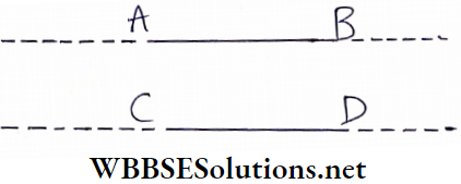
Solution:
Force per unit length on wire AB due to the magnetic field produced by wire CD
⇒ \(\frac{\mu_0}{4 \pi} \frac{2 I_1 I_2}{r}\)
where Ix = 20 A, I2 = 30 A and distance between AB and CD, r = 0.01m.
So force on the whole of wire AB due to wire CD,
⇒ \(\left.F=\frac{\mu_0}{4 \pi} \cdot \frac{2 I_1 I_2}{r} \times L \text { [where } L=\text { length of wire } A B\right]\)
Since wire AB is in equilibrium, the force F must balance its weight by acting downwards. This is possible only if the two wires repel each other and hence I1 and I2 are flowing in opposite directions.
Accordingly, \(F=\frac{\mu_0}{4 \pi} \cdot \frac{2 I_1 I_2}{r} \times L=M g\)…..(1) [where M=mass of wire AB]
If we consider that the wire is depressed by a small distance d so that the height of AB over CD becomes (r-d), then the force on wire AB increases to,
⇒ \(F_1=\frac{\mu_0 2 I_1 I_2}{4 \pi(r-d)} \times L=\frac{\mu_0 I_1 I_2}{2 \pi r}\left(1-\frac{d}{r}\right)^{-1} L\)
= \(=\frac{\mu_0 I_1 I_2}{2 \pi r}\left(1+\frac{d}{r}\right) L\)
Now on releasing the wire AB, it moves under the effect of restoring force f.
⇒ \(f=F_1-M g=F_1-F=\frac{\mu_0 I_1 I_2}{2 \pi r}\left[1+\frac{d}{r}-1\right] L\)
= \(\frac{\mu_0 I_1 I_2 L}{2 \pi r^2} d\)
Acceleration of the wire AB, \(a=\frac{f}{M}=\frac{\mu_0 I_1 I_2 L}{2 \pi r^2 M} d\)
Since, except d all other physical quantities are constants
Hence the motion of the wire is simple harmonic.
So time period,
⇒ \(T=2 \pi \sqrt{\frac{2 \pi r^2 M}{\mu_0 I_1 I_2 L}}=2 \pi \sqrt{\frac{2 \pi r^2}{\mu_o I_1 I_2 L} \times \frac{\mu_0 I_1 I_2 L}{2 \pi r g}}\) [putting the value of M from equation (1)]
∴ \(T=2 \pi \sqrt{\frac{r}{g}}=2 \pi \sqrt{\frac{0.01}{9.8}}\)
= 0.2s
Electromagnetism Derivations For Class 12 WBCHSE
Electromagnetism Galvanometer
A galvanometer is an instrument used to detect and measure the current in a circuit.
A current measuring instrument can be constructed using the heating effect, the chemical effect, or the magnetic effect of current. However, to measure a direct current (dc), the magnetic effect is most advantageous for practical purposes.
The two types of galvanometers used widely in laboratories are:
1. Moving magnet galvanometer: The basic principle of this instrument is the action of electric current on a magnet.
Example: Tangent galvanometer, Since galvanometer, Helmholtz double coil galvanometer.
This type of galvanometer is rarely used due to its disadvantageous setup and low sensitivity. The discussion is out of our syllabus.
2. Moving coil galvanometer: The basic principle of this instrument is the action of a magnet on an electric current.
Example: D’Arsonval galvanometer, table galvanometer.
Moving Coil Galvanometer:
With a moving coil galvanometer, we can detect and measure even a very weak current (about 10-9A) in a circuit. This galvanometer.
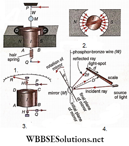
Description of a moving coil:
ABCD: A coil of insulated copper wire wound over a rectangular frame made of cane or aluminum.
I: A cylinder of soft iron. The axis of the cylinder coincides with the axis of the coil and the cylinder is fitted inside the coil.
NS: Two magnetic poles made of soft iron attached with a strong permanent magnet. The gap between the two poles is cylindrical and in this gap, the coil is placed in such a way that the axis of the gap coincides with the axis of the coil.
Due to this special shape of the magnetic poles, the magnetic field always remains parallel to the plane of the coil.
Now this coil is fitted with a mechanical system such that:
- The circuit current to be measured can be sent directly through the coil
- A very accurate measurement of the deflection of the coil due to the flow of current can be done. For this purpose, two types of mechanical arrangements are widely used
1. Suspended-coil galvanometer or D’Arsonval galvanometer: This type of arrangement.
W: Phosphor-bronze wire. The coil ABCD is hung by this wire.
M: A small mirror attached to the phosphor-bronze thread W. Ift he coil rotates through an angle θ, and the mirror also rotates through θ. So, if a ray of light falls on the mirror from a stationary source of light, the reflected ray rotates through an angle of 20. If the displacement of the reflected light spot on a scale, kept at a distance D from the mirror, is d then,
⇒ \(2 \theta=\frac{d}{D} \quad(\text { when, } d \ll D)\)
or, \(\theta=\frac{d}{2 D}\)….(1)
For this arrangement, it is also called a mirror galvanometer.
b This arrangement is shown. Two magnetic poles are not drawn here.
HH: Two hairsprings. Two ends of the coil are connected with these two hairsprings. The circuit current to be determined enters the coil through the two bearings P and Q attached to HH.
R: A pointer. With the rotation of the coil, it also rotates. When no current flows through the galvanometer, the pointer remains vertical. It can move on either side of this position depending on the direction of the current.
The deflection of the pointer gives an idea of the magnitude of the current. The tire value of the rotation is obtained from a graduated circular scale. Titus it is also called a pointer galvanometer.
Theory: Let the number of turns of the rectangular coil = N, the area of its surface A, the magnetic field parallel to the coil = D, and current through the coil = I. The torque acting on the coil, \(\tau=B N I A\) Due to torque, the coil rotates from its equilibrium position.
On the other hand, the phosphor-bronze thread in a suspended coil galvanometer or the hairsprings in a table galvanometer always tries to return the coil to its equilibrium position by virtue of its elastic property.
The value of this restoring torque \(\tau\)‘ is directly proportional to the tire angle of deflection of the coil. So, if the tire coil comes to rest at an angular displacement of θ
⇒ \(r=r^{\prime} \text { or, } B N I A=c \theta\)
or, \(I=\frac{c}{B N A} \cdot \theta\)….(2)
Here, c = restoring torque per unit twist = constant. From this equation, the tire value of the current can be obtained.
Using equation (1) for a suspended coil galvanometer we get,
⇒ \(I=\frac{c}{2 B N A D} d\)….(3)
WBCHSE Class 12 Physics Electromagnetism Notes Discussions:
1. Relation between current and angle of deflection: From equation (2), it is seen that current (I) is directly proportional to the angle of deflection (θ), i.e., a linear relation exists between them. Thus, the current measuring scale of this kind of galvanometer is always uniform.
2. Setting of the galvanometer: This galvanometer contains no magnetic needle and hence it is not necessary to set this galvanometer magnetic meridian plane. Rather, it can be placed in any position.
3. Galvanometer sensitivity: A moving coil galvanometer is very sensitive and current can be measured very accurately with it. Thus, this type of galvanometer is widely used for current measurement.
Suspended-type galvanometers are highly sensitive. The current through the coil for which the displacement of the light spot on a scale kept at a distance of 1 m from the mirror is 1 .mm, which is called the sensitivity of the galvanometer. Its unit is A mm-1
The sensitivity of this kind of galvanometer is about 10-9 A.mm-1.So, the galvanometer will be more sensitive for a lesser value of sensitivity.
On the other hand, a table galvanometer is very durable in spite of our lower sensitivity. Different table galvanometers are so designed that their pointers give full-scale deflection for a current range of 50μA to 15 mA
4. Condition of sensitivity:
From equation (2) we get, \(\frac{\theta}{I}=\frac{B N A}{c}\)
So, for a given current I, to get greater deflection θ, the value of \(\frac{B N A}{c}\) should be greater.
- Using a powerful magnet the value of B can be increased.
- A rectangular coil of multiple turns (N) and of sufficiently large surface area (A) has to be used. However, with an increase of N and A, the resistance of the galvanometer also increases and the coil becomes very heavy.
- A suspension thread should be chosen for which c is sufficiently small and hence a very thin wire should be used which can bear the weight of the coil. A suspension wire made of phosphor bronze serves this purpose
5. Limitation: The main disadvantage of a moving coil galvanometer is overload. If the current is more than its endurance limit and is passed through this galvanometer, its phosphor bronze wire or the hairsprings may get damaged permanently.
Electromagnetism Use Of Galvanometer As An Ammeter Or A Voltmeter
Ammeter: The instrument which measures current in an electrical circuit is called an ammeter. An ammeter is always connected in series with a circuit so that the entire current in the circuit can pass through it, Again, its resistance should be very low so that when it is joined in a circuit, the main current in that circuit does not decrease appreciably.
So, an ammeter milliammeter or microammeter) is a low-resistance instrument connected in series with an electrical circuit. The resistance of an Ideal ammeter should be zero.
Voltmeter: The instrument used for measuring the potential difference between two points of an electrical circuit is called a voltmeter. To equalize the potential difference between those two points with the potential difference between the two ends of the voltmeter, it should be connected in parallel with those two points in the circuit.
Again, the resistance of the voltmeter should be very high so that no appreciable fraction of the main current passes through the voltmeter. So, a voltmeter (or millivoltmeter) is an instrument of high resistance connected in parallel with an electrical circuit. The resistance of an ideal voltmeter should be infinite.
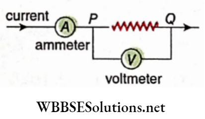
Disadvantages of using a galvanometer: The basic instrument used for measuring current is a moving magnet galvanometer or a moving coil galvanometer. In spite of this, there are some problems with using these instruments directly in laboratory experiments.
1. Some time is spent on leveling and setting of these galvanometers.
2. The magnitude of the current cannot be obtained directly from any scale. To calculate the magnitude of current we have to use the galvanometer formula after measuring the angle of deflection.
3. Usually the resistance of a galvanometer is of intermediate order (in most of cases, from 100Ω to 500Ω). When this galvanometer is used to measure current or potential difference, the results turn out to be erroneous; because it is not an ideal one to use as an ammeter as its resistance is not too low, and again it is not an ideal one as a voltmeter as its resistance is not too high.
Transformation of Galvanometers:
To make a galvanometer fit for everyday use in the laboratory, it should be effectively converted into an ammeter or a voltmeter. Thus, a galvanometer is the primary instrument while an ammeter or a voltmeter is the secondary instrument.
To construct an ammeter or a voltmeter, a moving coil table galvanometer is generally used. For this
The resistance of the galvanometer, G;
The current IG, for the full-scale deflection of the pointer in the circular scale, should be known beforehand.
Galvanometer to ammeter: Let the resistance of the galvanometer = G and the current required for the full-scale deflection of the pointer = IG
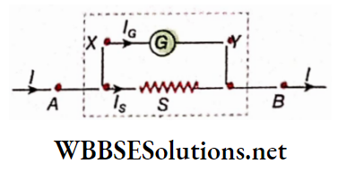
Now, a low resistance in parallel, i.e., a shunt S is connected with the galvanometer. The whole system is kept in a box covered with glass in such a way that
The pointer and the circular scale remain visible from the outside,
The terminals A and B are outside the box. The points A and B are connected with the external circuit. If the main circuit current corresponds to a full-scale deflection of the galvanometer, the galvanometer is effectively converted into an ammeter suitable for measuring maximum current I. Note that, due to the parallel combination of G and S, the equivalent resistance of the ammeter thus formed becomes sufficiently small.
Galvanometer to ammeter Calculation:
VX – VY = IG.G = IS.S [here, Is stands for shunt current]
So, \(S=\frac{I_G}{I_S} \cdot G\)
Again, \(I=I_G+I_S \quad \text { or, } \quad I_S=I-I_G\)
Hence, \(S=\frac{I_G}{I-I_G} \cdot G\)….(1)
So, to convert the galvanometer into an ammeter to measure a maximum current I, a shunt S as obtained from equation (1), should be connected in parallel with the galvanometer.
Range of the ammeter: In equation (1), I > IG; hence when an ammeter is constructed from a galvanometer, its range always increases and never decreases. If this range becomes n times, \(\frac{I}{I_G}=n\); so from equation (1) we get,
⇒ \(S=\frac{1}{I / I_G-1} \cdot G=\frac{G}{n-1}\) ….(2)
Resistance of the ammeter: The equivalent resistance of G and S is the resistance (R) of the ammeter.
So, \(\frac{1}{R}=\frac{1}{G}+\frac{1}{S}=\frac{1}{G}+\frac{n-1}{G}=\frac{n}{G} \text { i.e., } R=\frac{G}{n}\)…(3)
Galvanometer to voltmeters: In this case, a high resistance R is connected in series with the galvanometer. The two points A and B are connected with the external circuit.
So, if the current in the external circuit is IG, the galvanometer current will also be and as a result, the pointer gives full-scale deflection. Hence, In this condition, the potential difference (VA – VB) between the two points A and B will show full-scale deflection of the pointer.
So, the galvanometer will then be effectively converted into a voltmeter. Due to the series combination of G and R, the equivalent resistance of the voltmeter becomes sufficiently large.
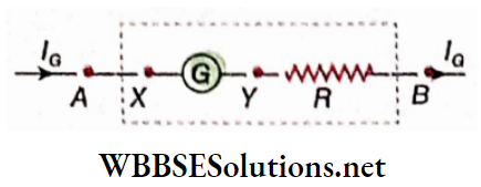
Galvanometer to voltmeters Calculation:
VA – VB = V = IG (G+R)
or, \(G+R=\frac{V}{I_G} \quad .. R=\frac{V}{I_G}-G\)….(4)
So, to convert the tire galvanometer into a voltmeter fit for measuring a maximum potential difference V, high resistance of magnitude R, as obtained from equation (4), should be connected in series.
Range of voltmeter: In equation (4), V > IGG (= VG), and hence if a galvanometer is converted into a voltmeter, the range of the voltage always increases and never decreases.If this range becomes n -times, then \(\frac{V}{V_G}=n\); So from equation (4) we get,
⇒ \(R=G\left(\frac{V}{I_G \cdot G}-1\right)=G\left(\frac{V}{V_G}-1\right)=G(n-1)\)…(5)
Resistance of the voltmeter: Naturally, the resistance of the newly formed voltmeter,
RV = G + R = G + G(n-l) = nG….(6)
WBCHSE Class 12 Physics Electromagnetism notes Differences between an ammeter and a voltmeter:
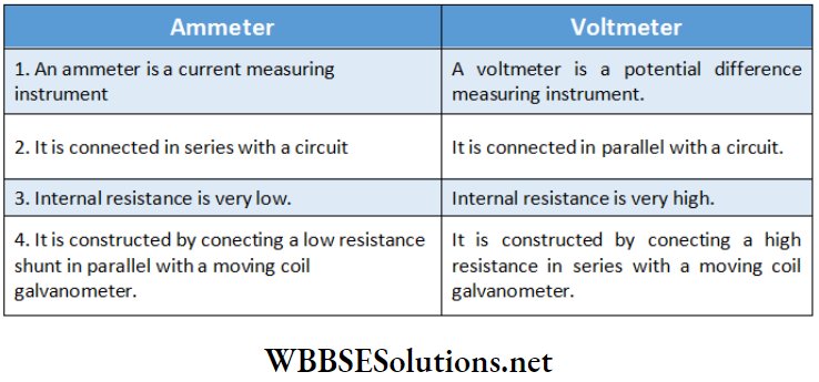
Theoretically moving magnet or suspended-coll galvanometers may be converted to an ammeter or voltmeter in a similar way. However due to the practical difficulties associated with such arrangements only moving coil table galvanometers are converted to be used as an ammeter or voltmeter.
WBCHSE Class 12 Physics Electromagnetism Notes
Electromagnetism Numerical Examples
Example 1. A galvanometer of resistance 10Ω gives lull scale deflection for a current of 10 mA. How can this galvanometer be used?
- As an ammeter to measure current of range 0-2 A
- As a voltmeter having a voltage range of 0-5 V?
Solution:
Resistance of the galvanometer, G = 10-11; maximum current, IG = 10 mA = 0.01 A
1. Connecting a shunt S in parallel to the galvanometer, if the instrument is used between points A and B, an ammeter of current range 0-1 will be obtained.
In the given question, I = 2 A.
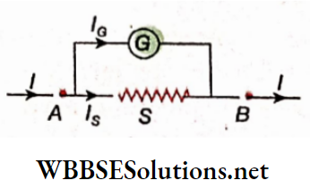
Now, IS.S= IG.-G
or, \(S=\frac{I_G}{I_S} G=\frac{I_G}{I-I_G} \cdot G=\frac{0.01}{2-0.01} \times 10\)
= 0.0503Ω
This is the required value of the shunt resistance.
2. A voltmeter having a voltage range of zero to (VA – VG) is obtained if a resistance R is connected in series with the galvanometer and the instrument is used between points A and B.
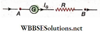
In the given problem, VA – VB = 5V
Now, VA – VB = IG (G + R)
or, \(R=\frac{V_A-V_B}{I_G}-G=\frac{5}{0.01}-10\)
= 500-10
= 490Ω
Example 2. Full-scale deflection occurs, in a moving coil galvanometer of resistance 36Ω when 100 mA current flows through it. What arrangement should be made to convert it into a voltmeter in the 0-5V range? Draw the necessary circuit diagram.
Solution:
Resistance of the galvanometer = 36Ω, maximum current, IG = 100 mA = 0.1 A.
Connecting a resistance R in series with the galvanometer and using the equipment in between the two points A and B, we shall get a voltmeter to measure voltage difference ranging from 0 to (VA– VB).
Here, VA – VB = 5V
Now, VA – VB = IG(G+R)
or, \(R=\frac{V_A-V_B}{I_G}-G=\frac{5}{0.1}-36\)
= 50-36
= 14Ω
This is the required value of the resistance R.
Example 3. A millivoltmeter of range ‘0-50 mV’ and resistance 50Ω is to be converted into an ammeter of range 0-1 A. How can it be done?
Solution:
Resistance of the millivoltmeter, R = 50 Ω; maximum voltage, V = 50 mV = 0.05 V.
Connecting a shunt S in parallel with the millivoltmeter and using this combination in between points A and B, we shall get an ammeter to measure a maximum current I.
Here, I = 1 A.
Now, IS. S = IV.R
or, \(S=\frac{I_V}{I_S} \cdot R=\frac{I_V}{I-I_V} \cdot R\)
⇒ \(\frac{\frac{V}{R}}{I-\frac{V}{R}} \cdot R=\frac{V}{I-\frac{V}{R}}=\frac{0.05}{1-\frac{0.05}{50}}=\frac{0.05}{1-0.001}=0.05 \Omega\)
This is the required value of the shunt resistance.
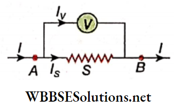
Example 4. How would you convert a voltmeter that can measure up to 150 V to an ammeter that can measure current up to 8R The Resistance of the voltmeter is 300Ω.
Solution:
Resistance of the voltmeter, R = 300Ω; maximum voltage, V = 150 V.
∴ Maximum current through the voltmeter,
⇒ \(I_V=\frac{V}{R}=\frac{150}{300}=0.5\)
Connecting a shunt S in parallel with the voltmeter and using this combination in between the points A and B, we shall get an ammeter to measure a maximum current I.
Here, I = 8 A
Now, IS.S = IV.R
or, \(S=\frac{I_V}{I_S} \cdot R=\frac{I_V}{I-I_V} \cdot R=\frac{0.5}{8-0.5} \times 300=\frac{0.5}{7.5} \times 300\)
= 20Ω
This is the required value of the shunt resistance.
Example 5. A galvanometer of resistance 100Ω gives full-scale deflection for a current of 10 mA. What is the value of, the shunt to be used to convert it into an ammeter which can measure current up to 10 A?
Solution:
Resistance of the galvanometer, G= 100Ω; maximum current, IG = 10 mA = 0.01 A. Connecting a shunt S in parallel with the voltmeter and using this combination in between the points A and B, we shall get an ammeter useful to measure a maximum current I.
Here, I = 10A and IS.S = IG.G
or, \(S=\frac{I_G}{I_S} \cdot G=\frac{I_G}{I-I_G} \cdot G=\frac{0.01}{10-0.01} \times 100=\frac{1}{9.99}\)
= 0.1001Ω
Example 6. A moving coil galvanometer of resistance 50Ω gives full-scale deflection for a current of 50 mA. How can this galvanometer used to convert it into a voltmeter that can measure voltage up to 200 V?
Solution:
Resistance of the galvanometer, G = 50Ω; maximum current, IG= 50 mA = 0.05 A. Connecting a resistance R in series with the galvanometer and using the equipment in between the two points A and B, we shall get a voltmeter to measure the voltage difference ranging from 0 to ( VA– VB)
Here, VA – VB = 200V
Now VA – VB = IG(G+R)
or, \(R=\frac{V_A-V_B}{I_G}-G=\frac{5}{0.1}-36=14 \Omega\)
This is the required value of resistance R.
WBCHSE Class 12 Physics Electromagnetism notes
Electromagnetism Conclusion
- Two like poles repel each other and two unlike poles attract each other.
- Repulsion is the conclusive test of magnetization.
- The region surrounding a magnet in which the influence of the magnet is felt is called the magnetic field of the magnet.
- A magnetic line of force in a magnetic field is defined as a continuous line such that the litigant drawn at any point on it gives the direction of the magnetic field at that point.
- The direction of deflection of a magnetic needle due to the flow of electric current can be determined by
- Ampere’s swimming rule
- Right-hand thumb rule.
- The right-hand thumb rule is also called Oersted’s rule. For determination of the direction of the magnetic field at a point near a current-carrying conductor)
- Maxwell’s corkscrew rule
- The right-hand grip rule is used. The ratio of the magnetic field (B) acting at a point by a substance to the magnetic permeability (μ) of that substance is called the magnetic intensity or magnetizing field (H) at that point.
Units of B and H:
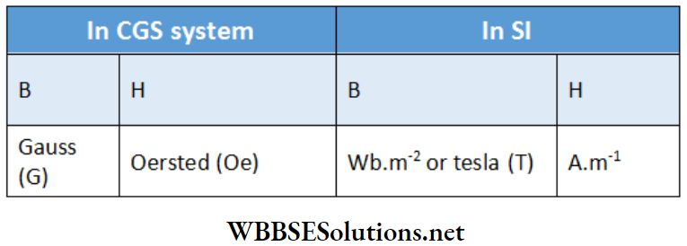
Relation between SI and CGS units:
- 1A.m-1 = 4π x 10-3 Oe , 1Wb.m-2 = 104 G
- The current which, when flowing through a conducting wire of length 1 cm bent in the form of an arc of a circle of radius 1 cm, produces a magnetic field of 1 Oe at the center of the arc, is called an electromagnetic unit of current.
- 1 emu of current =10 A.
- Ampere’s circuital law: The line integral of the magnetic field vector along a closed path in a magnetic field is equal to the product of the total current enclosed by the closed path and the permeability of the vacuum.
- \(\text { i.e., } \oint \vec{B} \cdot \overrightarrow{d l}=\mu_0 I\)
- Here, I is the total current enclosed by the closed path.
- If a long, insulated conducting wire is wrapped over the surface of a cylinder in such a way that each circular turn is perpendicular to the axis of the cylinder, the coil thus formed is called a solenoid.
- If a long, insulated conducting wire is wound on a donut-shaped core of uniform cross-section having a circular axis such that each turn is perpendicular to its axis, the coil thus formed is called a toroid. A toroid is also called an endless solenoid.
- If a positively charged particle of magnitude 1 C moves with velocity 1m s-1 in a magnetic field and experiences a maximum force of 1 N, then the magnitude of the magnetic field is called 1 T or 1 Wb.m-2.
- The magnetic force experienced by a moving charged particle in a magnetic field is a no-work force.
- The speed and kinetic energy of a charged particle does not change when a magnetic force acts on it.
- If the magnitude and direction of a magnetic field throughout a certain region remain constant, the field is called a uniform magnetic field otherwise, it is a non-uniform magnetic field.
- A charged particle follows a circular path inside a uniform magnetic field when it enters the field perpendicularly. A charged particle follows a helical path inside a uniform magnetic field when it enters the tire field obliquely.
Fleming’s left-hand rule: If the tire forefinger of the middle finger and the thumb of the left hand are stretched mutually perpendicular to each other, such that the forefinger points the direction of the magnetic field and the tire middle finger points the direction of the current, the thumb points the direction of the force acting on tire conductor.
- Two like parallel currents attract each other and two unlike parallel currents repel each other.
- Two long, linear, and parallel conducting wires of negligible cross sections are kept 1 nr apart from each other. The steady direct current flowing in each wire for which both of them experience a force of 2 x 10⁻⁷ N.m-1 is called 1 A current.
- Galvanometers used in the laboratory are:
- Moving magnet galvanometer-examples: Tangent galvanometer, sine galvanometer.
- Moving coil galvanometer-examples: D’Arsonval galvanometer, table galvanometer.
- According to Biot-Savart law or Laplace’s law, die magnitude of magnetic field ⇒ \(\delta \vec{B}\) at a point due to a small element δ1 of a current carrying wire is,
- ⇒ \(\delta B \propto \frac{I \delta l \sin \theta}{r^2} \text { or, } \delta B=k \frac{I \delta l \sin \theta}{r^2}\)
- where r = distance of the point from the element and
- θ = angle between the current element \(\delta \vec{B}\) and position vector \(\vec{r}\).
- In SI, the conventional form of Biot-Savart law is,
- ⇒ \(\delta B=\frac{\mu_0}{4 \pi} \cdot \frac{I \delta l \sin \theta}{r^2}\)
- [μ0 = magnetic permeability of vacuum = 4π x 10-7 H.m-1]
- Generally, \(B=\mu H \quad \text { or, } \quad H=\frac{1}{\mu} B\)
- The magnetic field at any point near a straight conductor,
- ⇒ \(B=\frac{\mu_0}{4 \pi} \frac{I}{r}\left(\sin \theta_1+\sin \theta_2\right)\)
- Magnetic field due to an Infinite straight conductor,
- ⇒ \(B=\frac{\mu_0}{4 \pi} \cdot \frac{2 l}{r}\)
- The magnetic field at the center of a circular conductor of N turns,
- ⇒ \(B=\frac{\mu_0 I N}{2 r}[r=\text { radius of the circle }]\)
- The magnetic field at a point on the axis of a circular conductor of N times,
- ⇒ \(B=\frac{\mu_0 N I}{2} \cdot \frac{r^2}{\left(r^2+x^2\right)^{3 / 2}}\)
- [where, x = distance of the point from the center of the coil]
- Magnetic field due to a long, straight solenoid at any point on its axis,
- ⇒ \(B=\mu_0 n I\)
- [n = number of turns per unit length of the solenoid = \(\frac{N}{L}\)
- Magnetic field due to a toroid,
- ⇒ \(B=\mu_0 n I\)
- [n = number of turns per unit length of the toroid = \(\frac{N}{2 \pi r}\)]
- If N number of conductors carrying current I are enclosed by a closed loop then according to circuital law,
- ⇒ \(\oint \vec{B} \cdot d \vec{l}=\mu_0 N I\)
- Force on a charged particle moving with a velocity (\(\vec{v}\)) in a uniform magnetic field (\(\vec{B}\)) is
- ⇒ \(\vec{F}=q \vec{v} \times \vec{B}\)
- The radius of the circular path described by a moving charged particle entering a uniform magnetic field perpendicularly,
- ⇒ \(r=\frac{m v}{q B}\)
- [m = mass of the charged particle, v = velocity of the particle, q = charge of the particle and B = magnetic field]
- Time period of revolution, \(T=2 \pi \frac{m}{q B}\)
- Number of complete revolutions in the circular path, i.e., frequency of circular motion,
- ⇒ \(n=\frac{1}{T}=\frac{1}{2 \pi}\left(\frac{q}{m}\right) B\)
- This is known as cyclotron frequency.
- The kinetic energy of the charged particle ejected from the outlet of the cyclotron device = \(\frac{q^2 B^2 R^2}{2 m}\) [ R = radius of the dee of cyclotron]
- A charged particle, when it enters a magnetic field obliquely, follows a helical or spiral path. The pitch of this spiral or helical path
- = time period x linear velocity
- = circumference of the circular path x cotθ
- Force experienced by a particle of charge + q in a uniform electric field
- ⇒ \(\vec{F}=q \vec{E}\)
- For a charge q moving in an electromagnetic field with velocity \(\vec{v}\), the forces acting are,
- Electric force, \(\vec{F}_e=q \vec{E} \quad[\vec{E}=\text { electric field }]\)
- Magnetic force, \(\vec{F}_m=q \vec{v} \times \vec{B}[\vec{B}=\text { magnetic field }]\)
- Resultant Lorentz force, \(\vec{F}=q(\vec{E}+\vec{v} \times \vec{B})\)
- In the case of a current-carrying conductor in a magnetic field, the resultant magnetic force acting on the whole circuit or a finite part of the circuit,
- ⇒ \(F=\int d F=\int B I d l \sin \theta\)
- The torque acting on a rectangular conductor having N turns placed in a uniform magnetic field,
- ⇒ \(\tau=B N I A\) [I = current-strength, A = area of cross-section of the rectangular conductor]
Vectorial form:
- ⇒ \(\vec{\tau}=N I \vec{A} \times \vec{B}\)
- If the perpendicular distance between two long parallel conductors kept in vacuum or in air be r, the force of attraction or repulsion per unit length of the wire is,
- ⇒ \(F=\frac{\mu_0}{4 \pi} \cdot \frac{2 I_1 I_2}{r}\) [I1 , I2 are the currents in the two wires]
- In the case of a moving coil galvanometer, if the number of turns in the tire coil is N, the area of the plane of coil A, the magnetic field parallel to coil B, current the of the coil I, and the coil comes to rest at an angle θ, then
- ⇒ \(I=\frac{c}{B N A} \theta\)
- Here, c = restoring torque per unit deflection = constant
- Required shunt to be connected with a galvanometer in parallel to convert it to an ammeter,
- ⇒ \(S=\frac{I_G}{I-I_G} \cdot G\)
- [where S = shunt resistance, G = galvanometer resistance, IG = maximum galvanometer current, I = main current in circuit]
- If the range of an ammeter is to be increased n -times,
- ⇒ \(S=\frac{G}{n-1}\)
- To convert a galvanometer into a voltmeter for measuring a maximum voltage of V, the resistance to be connected in series with the galvanometer,
- ⇒ \(R=\frac{V}{I_G}-G\)
- If the range of the voltmeter is to be increased n -times, then
- R = G(n-l)
Units of some magnetic quantities:
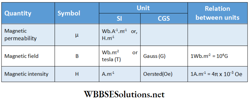
- When two current-carrying loops make an angle θ with each other, then net magnetic field at their center,
- ⇒ \(B=\sqrt{B_1^2+B_2^2+2 B_1 B_2 \cos \theta}\)
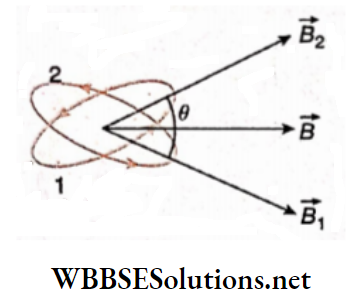
- The value of the magnetic field at at point on the center of separation of two parallel conductors carrying equal currents in the same direction is zero.
- If a current-carrying circular loop is turned into a coil having n identical turns then the magnetic field at the center of the coil becomes n² times the previous electric field i.e., Bn = n²B1 where Bn = magnetic field at the center of the coil having n turns; B1 = magnetic field at the center of the circular loop.
Electromagnetism Very Short Questions and Answers
Question 1. What is the nature of lines of force in a uniform magnetic field?
Answer: Parallel and equispaced
Question 2. In a uniform magnetic field, lines of force are equispaced – straight lines.
Answer: Parallel
Question 3. How is the direction of a magnetic field $ at a point related to the magnetic line of force passing through that point?
Answer:
⇒ \(\vec{B}\) is tangential to the line of force at that point
Question 4. A magnetic needle is kept below a very long conducting wire. If the current is sent through the wire from north to south, in which direction will the north pole of the needle be deflected?
Answer: Toward the east
Question 5. A magnetic needle is placed below a very long conducting wire. If the current is sent through the wire from east to west, in which direction will the north pole of that needle be deflected?
Answer: No deflection occurs
Question 6. How does the magnetic field at a point near a long straight current-carrying conductor vary with the current and the distance of the point?
Answer: Proportional, inversely proportional
Question 7. When 1 A current flows through a circular conductor, the magnetic: fields generated at its centre are 10-7 T. For what value of current, will the magnetic field be 10-6 T?
Answer: 10 A
Question 8. Which physical quantity has the unit Wb.m-2? Is it a scar lar or a vector quantity?
Answer: Magnetic field or magnetic induction \(\vec{B}\) it is a vector quantity
Question 9. What is the unit of magnetic permeability μ0 of vacuum?
Answer: H.m-1
Question 10. What is the magnetic field produced at a distance of 1 m from a long, straight conductor carrying 1 A current?
Answer: 2 x 10⁻⁷ T
Question 11. The magnetic field at a distance of 1 m from a long, straight conductor is 10-7 T. What is the current through the conductor?
Answer: 0.5 A
Question 12. Consider the circuit where APB and AQB are semi-circles. What is the magnetic field at the center C of the circular loop?
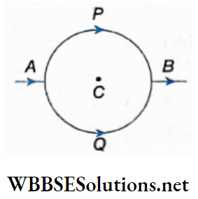
Answer: Zero
Question 13. A solenoid carrying 1 A current has a length of 1 m and contains 10000 turns. What is the magnetic field on the axis of the solenoid?
Answer: 4π x 10-3T
Question 14. What will be the nature of the path of a charged particle when it enters a uniform magnetic field 5 normally?
Answer: Circular
Question 18. An electron and a proton enter a uniform magnetic field perpendicularly with the same speed. How many times larger will be the radius of the proton’s path than that of the electron’s path? Given: the proton is 1840 times heavier than the electron
Answer: 1840
Question 19. Can a stationary charge produce a magnetic field?
Answer: No
Question 20. What is the magnitude of force experienced by a stationary charge placed in a uniform magnetic field?
Answer:
⇒ \(\vec{F}_m=q \vec{v} \times \vec{B}=0(… \vec{v}=0)\)
Question 21. Does any force act on a magnetic north pole ifit is brought near a negatively charged conductor at rest?
Answer: No
Question 22. Does any force act on a charge moving in a magnetic field?
Answer:
⇒ \(\text { yes, } \vec{F}=q \vec{v} \times \vec{B}\)
Question 23. A long straight wire is carrying a current. An electron starts its motion on a line parallel to the wire in a direction same as that of the current. What will be the direction of the force on the electron?
Answer: Away from the wire in a normal direction
Question 24. A charge q moves with velocity \(\vec{v}\) at an angle 6 to a magnetic field P. What is the force experienced by the particle?
Answer: qvBsinθ
Question 25. An electron moving with a velocity of 107m.s-1 enters a uniform magnetic field of 1 T along a direction parallel to the field. What would be its trajectory?
Answer: Undeviated straight line
Question 26. A certain proton moving through a magnetic field region experiences maximum force. When does this occur?
Answer: The velocity of the proton is perpendicular to the magnetic field
Question 27. An electron beam projected along the positive x-axis experiences a force, due to a magnetic field, along the positive y-axis. What is the direction of the magnetic field?
Answer: Positive z-axis
Question 30. What is the mutual action between two, unlike parallel currents?
Answer: Repulsion
Question 31. Two long and straight parallel wires carry a current 1 A each. If the distance between the two wires is 1 m, what will be the force acting per unit length on them?
Answer: 2 x 10⁻⁷ N.m-1
Question 32. What type of galvanometer is used to prepare an ammeter or a voltmeter in the laboratory?
Answer: Moving coil table galvanometer
Question 33. In the case of a moving coil galvanometer, what is the relation between the current I and the angle of deflection θ?
Answer: Proportional
Question 34. How is a galvanometer converted into an ammeter?
Answer: By connecting a rightly chosen low-resistance shunt in parallel to it
Question 35. How should a resistance be connected with a galvanometer to convert it into a voltmeter?
Answer: In series
Question 36. What is the nature of the magnetic field in a moving coil galvanometer?
Answer: Radial
Electromagnetism Assertion Reason Type
Direction: Those questions have Statement 1 and Statement 2, Of the four choices given below, choose the one that best describes the two statements.
- Statement 1 is true, Statement 2 is true; Statement 2 is a correct explanation for statement I.
- Statement 1 is true, Statement 2 Is true; Statement 2 is not a correct explanation for Statement 1.
- Statement 1 is true, Statement 2 is false.
- Statement 1 is false, and Statement 2 Is true.
Question 1.
Statement 1: A magnetic needle that can rotate in a horizontal plane undergoes a deflection when current is passed through a conducting wire, placed above and parallel to it.
Statement 2: A magnetic field is developed around a current-carrying conductor.
Answer: 1. Statement 1 is true, Statement 2 is true; Statement 2 is a correct explanation for statement I.
Question 2.
Statement 1: A long straight conductor attracts iron filings when a current is passed through it.
Statement 2: A magnetic field is developed around a current-carrying conductor.
Answer: 4. Statement 1 is false, Statement 2 Is true.
Question 3.
Statement 1: I = 1 A and OA = 1 cm. The magnetic field developed at A is 10-5 Wb.m-2.
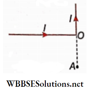
Statement 2: If I am the current flowing through a long straight conductor, then the magnetic field developed at a distance r from the conductor is \(B=\frac{\mu_0 I}{2 \pi r}\)
Answer: 2. Statement 1 is true, Statement 2 Is true; Statement 2 is not a correct explanation for Statement 1.
Question 4.
Statement 1: Neither the magnetic field vector \(\vec{B}\) nor the
magnetic intensity vector \(\vec{H}\) of a magnetic field depend on
the nature of the medium.
Statement 2: If the magnetic permeability of a medium is \(\mu \text { then } \vec{H}=\frac{1}{\mu} \vec{B}\)
Answer: 4. Statement 1 is false, Statement 2 Is true.
Question 5.
Statement 1: A galvanometer of resistance G is converted to an ammeter by increasing its range n times. The resistance of the ammeter is \(\frac{G}{n}\).
Statement 2: A shunt of resistance has \(\frac{G}{n-1}\) to be connected in parallel with a galvanometer in order to increase its range n times.
Answer: 1. Statement 1 is true, Statement 2 is true; Statement 2 is a correct explanation for statement I.
Question 6.
Statement 1: The velocity of injection of a charged particle, being accelerated in a cyclotron remains constant irrespective of the applied magnetic field.
Statement 2: In a cyclotron the charged particle is accelerated only due to the applied electric field because magnetic force is a no-work force.
Answer: 4. Statement 1 is false, Statement 2 Is true.
Question 7.
Statement 1: If an electron and a proton are projected with equal momentum in a uniform transverse magnetic field, then the curvature of their padis is equal.
Statement 2: The mass of a proton is much higher than that of an electron.
Answer: 2. Statement 1 is true, Statement 2 Is true; Statement 2 is not a correct explanation for Statement 1.
Question 8.
Statement 1: A charged particle moves perpendicular to a magnetic field. Its kinetic energy remains constant, but momentum changes.
Statement 2: A magnetic force acts on the charged particle.
Answer: 2. Statement 1 is true, Statement 2 Is true; Statement 2 is not a correct explanation for Statement 1.
Electromagnetism Match The Column
Question 1. Match the electromagnetic quantities in column A with the rules or formulae in column B.
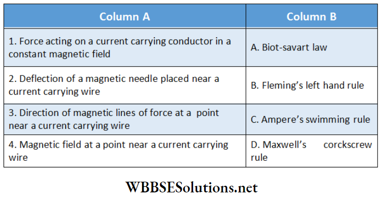
Answer: 1-B, 2-C, 3-D, 4-A
Question 2. The BC of the conductor is semicircular. Match the values of the magnetic field developed at O given in column 2 with the corresponding segments given in column 1.

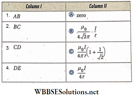
Answer: 1-A, 2-D, 3-B, 4-C
Question 3. A galvanometer of resistance 100Ω shows full-scale deflection for a current of 10 mA. Match the resistances in column 2 necessary to convert the galvanometer to an ammeter or voltmeter as given in column 1.
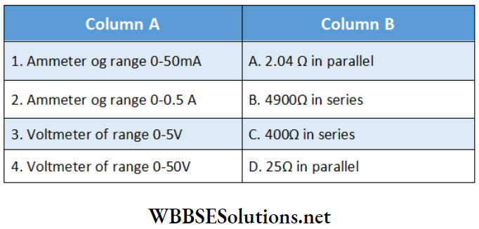
Answer: 1-D, 2-A, 3-C, 4-B
Question 4. Current in each of the two conductors parallel to each other and at a distance r is I (column 1). The magnetic fields at a point on the same plane and equidistant from the two conductors are given in column 2 (μ0 = 4π x 10-7 H.m-1)
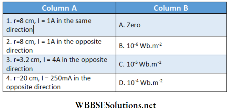
Answer: 1-A, 2-C, 3-D, 4-B
Question 5. A current-carrying wire. An electron at a point P moves with a velocity \(\vec{v}\). The direction of \(\vec{v}\) is given in column A and its deflection in column B. Match them.
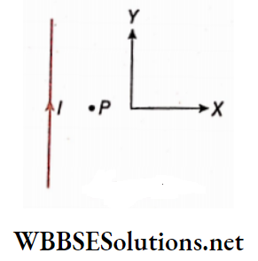
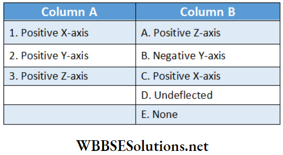
Answer: 1-B, 2-C, 3-D,