
WBCHSE Class 12 Physics Kirchhoff’s Laws Notes
Kirchhoff’s Laws And Electrical Measurement Kirchhoff’s Laws
Kirchhoff formulated the following two laws which enable us to find the distribution of current in complicated electrical circuits (or networks of conductors).
Kirchhoff’s First Law or Kirchhoff’s Current Law (KCL):
Statement: In an electrical circuit 9or network of wires) the algebraic sum of currents through the conductors as meeting at a point is zero, i.e., \(\Sigma i=0\)
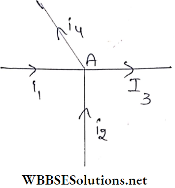
Kirchhoff’s Current Law Explanation of the law: Let us consider the number of wires connected at point A. Currents i1, i2, i3, and i4 flow through these wires in the directions. Here currents i1 and i2 are approaching point A while currents i3 and i4 are leaving point A. Taking current entering point A as positive current while current leaving point A as negative current and applying the first law we can write,
i1 + i2 – i3 – i4 = 0…(1)
Kirchhoff’s Current Law Discussion:
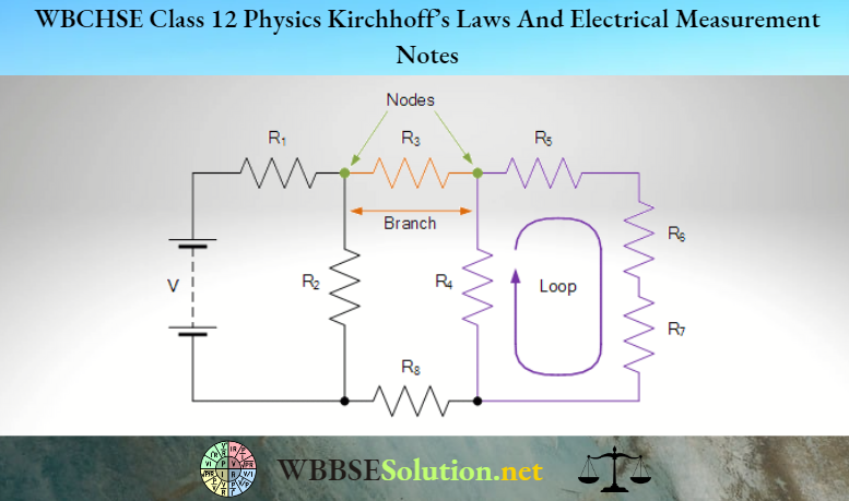
Node analysis: Any connecting point in an electrical circuit is called a node. By applying the first law of Kirchhoff, the analysis of an electrical circuit is called node analysis.
Conservation of electric charge: If we write equation (1) in the form i.e., i1 + i2 = i3 + i4, we can say that the sum of the currents approaching a connecting point = the sum of the currents leaving the point. If the current flows for time t we have
Read and Learn More Class 12 Physics Notes
⇒ \(i_1 t+i_2 t=t_3 t+i_4 t \quad \text { or, } q_1=q_2=q_3+q_4\)
i.e., the sum of the charges approaching the connecting point = the sum of the charges leaving the point.
The significance of the above equation is discussed below:
There cannot be any accumulation of charge at any connecting point in an electrical circuit
The charge cannot be created or destroyed, i.e., the total charge will remain constant
Kirchhoff’s Second Law or Kirchhoff’s Voltage Law (KVL):
Statement: The algebraic sum of the product of the current and resistance in any closed loop of a circuit is equal to the algebraic sum of electromotive force acting in that loop, i.e.,
⇒ \(\Sigma i r=\Sigma e\)
Explanation of the law: A closed-loop ACBDA within an electrical circuitIn the loop, current i1 is in a clockwise direction while current- i2 is in an anticlockwise direction. Taking clockwise current as positive and anticlockwise current as negative, i1 becomes positive and i2 becomes negative.
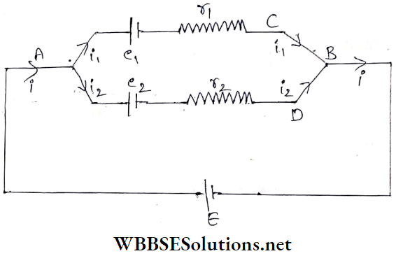
Again, the electromotive force of the sources that send currents in clockwise and anticlockwise directions in the closed loop are taken as positive and negative respectively.
So emf e1 becomes negative and emf e2 becomes positive. Hence, for the closed-loop ACBDA,
i1r1-i2r2 = -e1 + e2 ….(2)
We can write by applying Kirchhoff’s first law to the point A
i-i1-i2 = 0 on i2 = i – i1
So, equation (2) can be written as
i1r1 -(i-i1)r2
= –1+ e2
on i1(r1 + r2) = e2– e1 + ir2
or, \(i_1=\frac{\left(e_2-e_1\right)+i r_2}{r_1+r_2}\)….(3)
Knowing the values of die quantities of equation (3) we can determine i1 and i2.
WBBSE Class 12 Kirchhoff’s Laws Notes
Kirchhoff’s Voltage Law Discussion:
Mesh analysis: A complicated circuit formed by a number of adjacent loops resembles a mesh which can be analyzed one by one by applying Kirchhoff’s second law.
S3 Conservation of energy: We know that inside a source of electricity, other forms of energy are converted into electrical energy, and in an external circuit, electrical energy is converted into other forms of energy.
The amount of electrical energy developed inside a source of electricity to send a one-coulomb charge in a circuit is the electromotive force of the source. Again the amount of electrical energy spent in an external circuit due to the flow of one coulomb charge is the potential difference of the external circuit According to the second law of Kirchhoff,
⇒ \(\Sigma i r=\Sigma e \text { i.e., } \Sigma e=\Sigma v\) [potential difference, v = ir]
i.e., electrical energy developed in any circuit due to unit charge = electrical energy spent in the circuit
So, Kirchhoff’s second law obeys the law of conservation of energy
Class 12 Physics Electrical Measurement Notes
Kirchhoff’s Laws And Electrical Measurement Kirchhoff’s Laws Numerical Examples
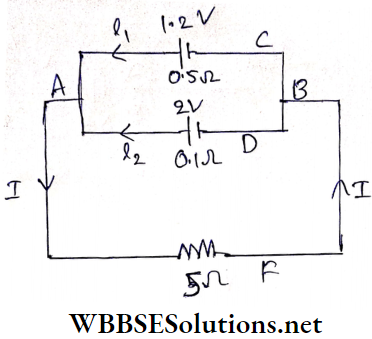
Example 1. Two cells, one of emf 1.2 V and internal resistance 0.5Ω, the other of emf 2 V and internal resistance 0.1Ω are connected in parallel and the combination is connected in series with an external resistance of 5Ω. What is the current through this resistor?
Solution:
Applying Kirchhoff’s first law to point A we have,
I1 + I2 – I = 0
or, I2 = I-I1 …..(1)
Applying Kirchhoff’s second law to the loop ACBDA we have,
-I1 x 0.5 + 12 x 0.1 = -1.2 + 2
-I1 x 0.3 -5-(I-I1) x 0.1 = 0.8
or, 0.1 I – 0.6I1 = 0.8 …….(2)
For the loop ADBFA,
-I2 x 0.1 – I x 5 = -2
or, (I-I1) x 0.1 + 5I = 2….(3)
Now, multiplying equation (3) by 6 and subtracting equation (2) from it we have,
⇒ \(30.5 I=11.2 \quad \text { or, } I=\frac{11.2}{30.5}=0.367 \mathrm{~A}\)
Example 2. Determine the current flowing through the resistor of resistance 200Ω and the potential difference across its ends.
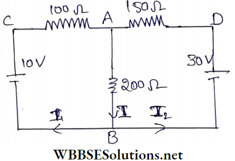
Solution:
Applying Kirchhoff’s first law to point B we have,
I-I1-I2 = 0…..(1)
Applying Kirchhoff’s second law to the loop ABCA we have,
100I1 + 200I = 10
or, 10I1 + 20I = 1….(2)
For the loop ADBA,
-200I-150I2 = -30
200I+ 150(I-I1) = 30
350I- 150I1 = 30
or – 15I1 + 35I = 3….(3)
From the equations (2) and (3) we get,
⇒ \(130 I=9 \text { or, } I=\frac{9}{130} \mathrm{~A}=69.2 \mathrm{~mA}\)
⇒ \(V_{A B}=\frac{9}{130} \times 200=\frac{180}{13} V \cdot 13.84\) V
Key Concepts in Kirchhoff’s Laws
Example 3. Twelve equal wires, each of resistance r ohm, are connected so as to form the frame of a cube. An electric current enters this cube at one corner and leaves from the diagonally opposite corner. Calculate the total resistance between the two corners.
Solution:
Let ADGCHEFB be the frame of the cube formed by twelve equal wires each of resistance r. Let the total current entering at the comer A and leaving the diagonally opposite comer B be 6x.
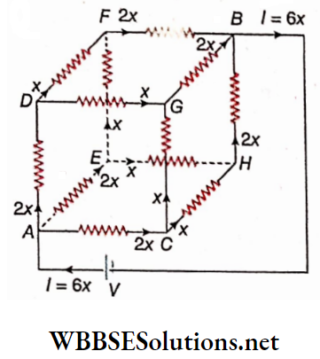
Therefore, the 12 wires of the cubic framework (mesh) will have equivalent resistance,
⇒ \(R=\frac{V}{I}=\frac{V}{6 x}\) …..(1)
As the resistance of each wire is the same, the current 6x is divided at A into three equal parts, one along AD, the other along AE and the third along AC.
At points D, E, and C the current is again divided into two equal parts. At points F, G, and H the currents combine so that the current in each of the arms FB, GB, and HB is 2x.
The currents at point B again combine. If V is the potential difference across A and B, then taking the path ACHBA and applying Kirchhoff’s second law we get,
2x.r + x.r + 2x.r = V
or, 5xr = V
From equations (1) and (2) we have,
6xR = 5xr
or, R = \(\frac{5}{6}\)r
| Class 11 Physics | Class 12 Maths | Class 11 Chemistry |
| NEET Foundation | Class 12 Physics | NEET Physics |
Node Voltage Loop Current:
Node voltage: During the analysis of any circular we can consider a potential for every connecting point i.e., node. This is called node voltage. For analysis circuit with the help of node voltage the following rules are adopted:
1. The potential of any connecting point of the circuit may be taken as zero, because for the calculation of current the potential difference between two points Is required whatever may be the Individual potential of the two points. In the potential of C Is taken ns zero.
2. If there is no source, of electricity or resistance (or condenser or inductance) between any two points, the potential of the two points is equal.
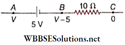
3. The potential of the negative terminal of a source of electricity is less than that of the positive terminal by the amount equal to the emf of the source. For Example, in the potential of A = V; the potential of B = (V- 5) V.
4. Current through any resistance is determined by applying the formula \(\frac{V}{R}\) = I. For Example, in the current through BC
⇒ \(I=\frac{V_B-V_C}{10}=\frac{(V-5)-0}{10}=\frac{V-5}{10}\)
5. After calculating the currents, Kirchhoff’s first law can be applied at various connecting points.
Loop Current: During the analysis of any circuit a separate current for every closed loop may be considered. This is called loop current.
For analysis of a circuit with the help of loop current the following rules are adopted:
1. Loop current is to be shown with a definite direction. For Example, in current i1 for the loop, ABCD is shown in the clockwise direction
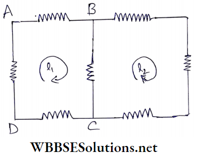
2. For the calculation of the current flowing in every branch of a loop the current in the adjacent loop is to be taken into account. For Example, in the current through AB, CD, and DA = i1, but current through BC = i1– i2.
3. Next Kirchhoff’s second law can be applied to the loop.
Class 12 Physics Electrical Measurement Notes
Kirchhoff’s Laws And Electrical Measurement Numerical Examples
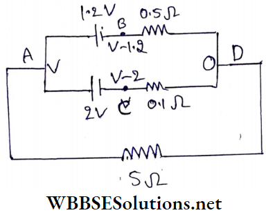
Example 1. Determine the current flowing through the resistance of 5Ω as shown In the circuit.
Solution:
Potentials of different connecting points are taken in the following way:
VA = V; VB = V-1.2;
VC = V – 2 and VD = 0
Current along \(B D=\frac{(V-1.2)-0}{0.5}=\frac{V-1.2}{0.5} \mathrm{~A}\)
Current along \(C D=\frac{(V-2)-0}{0.1}=\frac{V-2}{0.1} \mathrm{~A}\)
Current along \(A D=\frac{V-0}{5}=\frac{V}{5} \mathrm{~A} .\)
Applying Kirchhoff’s first law to the connecting point D we have,
⇒ \(\frac{V-1.2}{0.5}+\frac{V-2}{0.1}+\frac{V}{5}=0\)
or, \(\frac{10(V-1.2)+50(V-2)+V}{5}=0\)
or, 10V- 12 + 50V- 100 + V = 0
or, \(61 V=112 \text { or, } V=\frac{112}{61} \mathrm{~V}\)
∴ Current through resistance of \(5 \Omega=\frac{V}{5}=\frac{112}{61 \times 5}=0.367 \mathrm{~A}\)
Short Notes on Electrical Measurements
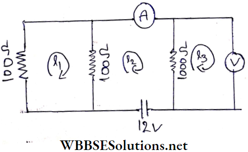
Example 2. The resistances of the ammeter and the voltmeter are 10Ω and 900Ω respectively. What are the readings of the ammeter and the voltmeter?
Solution:
In the circuit, currents flowing in the three loops have been shown as i1, i2, and i3 (clockwise).
From the second law of Kirchhoff’s, we get, for the first loop,
100i1 + 100(i1– i2) = 0
or, 2i1– i2 = 0 …..(1)
for the second loop,
100(i2-i1) + 10i2 + 100(i2– i3) = 12
or, – 100i1 + 210i2 – 100i3 = 12…(2)
fol the third loop,
100(i3 -i2) + 900 i3 = 0.
or, 10i3-i2 = 0 ….(3)
From (1) and (3),
i2 = 2i1 = 10i3
i1 = 5i3
Substituting these values in equation (2) we get,
-100 x 5i3 + 210 x 10i3 – 100i3 = 12
or, 1500i3 = 12
or, \(i_3=\frac{12}{1500}=\frac{4}{500} \mathrm{~A}\)
∴ Reading of voltmeter
= \(i_3 \times 900=\frac{4}{500} \times 900\)
= 7.2 V
and reading of ammeter
= \(i_2=10 i_3=10 \times \frac{4}{500}\)
= 0.08 A
Kirchhoff’s Laws And Electrical Measurements Class 12
Kirchhoff’s Laws And Electrical Measurement Potential Divider Or Potentiometer
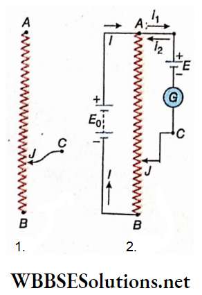
Potential Divider Or Potentiometer Description: A wire of uniform resistance is connected to two binding screws A and B. A slider or jockey J can move along the wire, remaining in contact with it. J is connected with the binding screw C. This arrangement is generally called a potential divider or potentiometer
Suppose, the length of the resistor AB = L; resistance = R, the
length of the portion AJ = l; its resistance = r.
Since the resistance of the resistor is uniform,
⇒ \(\frac{L}{l}=\frac{R}{r} \quad \text { or, } \quad r=\frac{l}{L} \cdot R\)….(1)
Uses:
Determination of the emf of a cell: Suppose, a source of emf E0 is connected between the two ends A and B of the potentiometer wire of resistance R. The cell whose emf E is to be measured is connected between the points A and C through a galvanometer G. It is to be noted that the positive pole of the cell is connected at A.
Now, suppose that the current in the circuit ACJA due to the effective emf VAC is ix and the current in that circuit due to the cell = i2. These two currents flow in opposite directions.
The slider J is shifted from point to point and placed at a position for which the current through the galvanometer is zero.
Clearly at that condition i1 = i2. If R0 is the total resistance of the circuit ACJA, then,
⇒ \(i_1=\frac{V_{A C}}{R_0} \quad \text { and } i_2=\frac{E}{R_0}\)
So for zero galvanometer current, \(\frac{V_{A C}}{R_0}=\frac{E}{R_0}\)
It is evident that the current l passes through AJ. So,
⇒ \(V_{A J}=\frac{E_0}{R} \cdot \frac{l}{L} \cdot R_i=\frac{l}{L} \cdot E_0 \quad \text { i.e., } V_{A C}=\frac{l}{L} E_0\)….(2) [length of 1 AB = L, length of AJ =l]
or, \(E=V_{A C}=\frac{l}{L} E_0\)…(3)
If we already know the values of E0 and L then by noting the value of l from the position of the slider, the emf E of the cell can be determined from the equation (3).
Important Definitions in Kirchhoff’s Laws
Comparison of the emfs of two cells: From equation (3) we can write, \(\frac{E}{E_0}=\frac{l}{L}\). So the ratio of the emfs of two cells can be determined with a potentiometer even though the emf of each cell may not be known.
Determination of the internal resistance of a cell: For the length of the potentiometer wire AJ1 = l1 (when the slider is placed at the point J1, if the galvanometer current is zero, according to the equation (3),
⇒ \(E=\frac{l_1}{L} E_0\)
Now, a known resistance R is to be connected parallel to the cell. Under this condition, the potentiometer circuit measures the potential difference V across R. If the galvanometer current is zero for the length of the potentiometer wire AJ2 = l2 (when the slider is placed at J2
⇒ \(V=\frac{l_2}{L} E_0\)…(4)
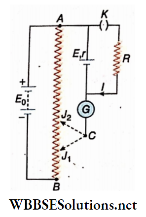
Therefore, \(\frac{V}{E}=\frac{l_2}{l_1}\left[\text { since, } E=\frac{l_1}{L} E_0\right]\)
Again if r is the internal resistance of the cell, E is the emf and I is the current in the circuit due to the cell, then
E = I(R + r) and V = IR
⇒ \(\text { i.e., } \frac{V}{E}=\frac{R}{R+r}\)
So, \(\frac{l_2}{l_1}=\frac{R}{R+r} \quad \text { or, } R+r=\frac{l_1}{l_2} \cdot R \quad \text { or, } r=\left(\frac{l_1}{l_2}-1\right) R\)
Therefore, to determine the internal resistance r of the cell, we have no need to know the values of L, E0, or E.
Measurement of the potential difference between two points of an electric circuit: The potential difference between any two points of a circuit car i be measured by using a potentiometer in the same way as the emf of a cell is measured.
One of the two points (M and N) of an electrical circuit across which the potential difference is to be measured, is connected to the end A of the potentiometer wire, and the other point is connected to the jockey J through a galvanometer G.
The two poles of the battery of emf E0 are connected to the ends A and B of the potentiometer wire in such a tray that the current i1 in the part AM due to the batten’ of emf E0 and the cu rent i2 due to the external circuit are opposite to each other.
Now changing the position of the jockey J from point to point we observe the position of the jockey. for which the galvanometer current is zero. In this position i1 = i2. Let the total resistance of the circuit MNJA be R0
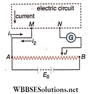
Then \(\left.i_1=\frac{V_{A J}}{R_0} \text { [length of } A B=L \text {, length of } A J=l\right]\)
and \(i_2=\frac{V_{M N}}{R_0} \quad \text { So, } V_{M N}=V_{A J}=\frac{l}{L} E_0\)….(5)
If the values of E0 and L are known, then by knowing the value of I from the position of J, the value of VMN i.e., the potential difference between M and N can be determined from the equation (5).
Condition of effectiveness: In this arrangement, the potentiometer behaves as a voltmeter. So like any voltmeter, the resistance of the potentiometer should be very high.
So the condition of measurement of potential difference by a potentiometer is that the resistance of the potentiometer wire between the two points A and J must be many times greater than the resistance between the two points M and N of the experimental circuit If it is not so, then as soon as the potentiometer is connected, the equivalent resistance between the points M and N of the experimental circuit will be reduced to a large extent and much error will be found in the measured value of VMN.
Kirchhoff’s Laws And Electrical Measurements Class 12
Kirchhoff’s Laws And Electrical Measurement Potential Divider Or Potentiometer Numerical Examples
Example 1. The length of the wire of a potentiometer is 100 cm and the emf of a standard cell connected to it is E volt. While measuring the emf of a battery having an Internal resistance of 0.5Ω. the null point is obtained at a length of 30 cm. Determine the emf of the battery.
Solution:
When the annuli point is obtained, no .current flows through the battery. So there is no internal potential drop. In this case, the internal resistance of the battery has no influence. So if E’ is the emf of the battery, then
⇒ \(\frac{E}{100}=\frac{E^{\prime}}{30} \quad \text { or, } \frac{E}{E^{\prime}}=\frac{10}{3}\)
or, E’ = 0.3E
Example 2. A potential difference of 220 V is applied at the two ends of a rheostat of 12000Ω. A voltmeter of resistance 6000 fl is connected between points A and D. If point D divides AB in the ratio of 1:4 what will be the reading of the voltmeter?
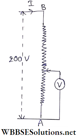
Solution:
⇒ \(\frac{A D}{B D}=\frac{1}{4} \quad \text { or, } \frac{A D+B D}{B D}=\frac{1+4}{4} \text { or, } \frac{A B}{B D}=\frac{5}{4}\)
or, \(B D=\frac{4}{5} A B=\frac{4}{5} \times 12000=9600 \Omega\)
∴ AD = AB – BD
= 12000-9600
= 2400Ω
If the voltmeter is connected between A and D, the equivalent resistance of the circuit
= \(9600+\frac{2400 \times 6000}{2400+6000}\)
= \(9600+\frac{24 \times 6000}{84}\)
⇒ \(\left(9600+\frac{2 \times 6000}{7}\right) \Omega\)
∴ Current \(I=\frac{220}{9600+\frac{2 \times 6000}{7}} \mathrm{~A}\)
∴ \(V_{B D}=I \times B D=\frac{220}{9600+\frac{2 \times 6000}{7}} \times 9600\)
⇒ \(\frac{220}{1+\frac{2 \times 6000}{7 \times 9600}}=\frac{220}{1+\frac{5}{28}}=\frac{220 \times 28}{33}=\frac{560}{3} \mathrm{~V}\)
⇒ \(V_{A D}=220-\frac{560}{3}=\frac{100}{3}\)
= 33.3V
Since the voltmeter is connected between points A and D, its reading will be 33.3 V.
Practice Problems on Kirchhoff’s Laws
Example 3. In a potentiometric arrangement, a cell is connected to the potentiometer wire of 60 cm in length to make the 1 deflection zero in the galvanometer. Now if the cell is shunted with a 6Ω resistor, a null point is found in the 50 cm length of the wire. What is the internal resistance of the cell?
Solution:
Here, shunt R = 6Ω, l1 = 60cm l2 = 50cm.
∴ Internal resistance of the cell
⇒ \(r=\left(\frac{l_1}{l_2}-1\right) R\)
= \(\left(\frac{60}{50}-1\right) \times 6\)
= \(0.2 \times 6\)
= \(1.2 \Omega\)
Example 4. A length of potentiometer wire of 188 cm balances the emf of a cell In the n circuit and its length of 135 cm when the cell tins a conductor of resistance 8Ω connected between Its terminals. Find the Internal resistance of
Solution:
Let the emf of the cell = E, and Its internal resistance =r. When a resistance R Is connected between Its terminals (here, R = 8Ω), the coll is subjected to an internal drop of potential Then, the terminal potential difference, the cell.
V=E-Ir
= \(E-\frac{E r}{R+r}\)
= \(E\left(1-\frac{r}{R+r}\right)\)
= \(E \frac{R}{R+r}\)
From the given data,
⇒ \(\frac{E}{V}=\frac{155}{135} \quad\)
or, \(\frac{R+r}{R}=\frac{155}{135} \quad\)
or, \(1+\frac{r}{R}=\frac{155}{135}\)
∴ \(r=R\left(\frac{155}{135}-1\right)=8 \times \frac{20}{135}\)
= 1.185Ω
Kirchhoff’s Current And Voltage Laws Class 12
Kirchhoff’s Laws And Electrical Measurement Wheatstone Bridge
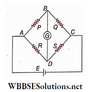
Description: Four resistances P, Q, S, and R form the four arms AB, BC, CD, and DA respectively of a quadrilateral ARCD.
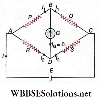
A battery B Is connected between A and C and a galvanometer of resistance G Is connected between B and D, This complete arrangement Is called a Wheatstone bridge circuit. In this circuit the first arm AB has resistance P, the second arm HC has resistance Q, the third arm AD has resistance it, and the fourth arm DC has resistance S.
Working principle: The resistances P, Q, R, and S for the four arms of the bridge are so selected that the galvanometer deflection is zero i.e., galvanometer current IG = 0. This Is called the null condition or balanced condition of the bridge.
In the null condition, the relation of the resistances is:
⇒ \(\frac{P}{Q}\) = \(\frac{R}{S}\) ….(1)
Of the four resistances, if three are known, the fourth resistance can be determined from the above relation. Usually, the unknown resistance is placed in the fourth arm i.e.,.in place of S.
Proof of the relation P/Q = R/S: In the null condition, IG = 0. So, the potential difference between the two ends of the galvanometer,
VB – VD = IG.G = 0 [G = resistance of galvanometer]
or, VB = VD
For IG = 0, suppose current in resistance P = current in resistance Q = I1 and current resistance R = current resistance S = I2.
∴ VA-VB = I1P; VA-VD = I2R
and VB-VC = I1Q; VD-VC = I2S
Now, Since VB = VD,
∴ I1P = I2R…(2)
and I1Q = I2S….(3)
Now, by dividing equation (2) by equation (3) we have,
⇒ \(\frac{P}{Q}\) = \(\frac{R}{S}\)
On the basis of this relation, the arms P and Q are called ratio arms.
Discussion:
1. Wheatstone bridge is used for measurement of ordinary resistances (from 1Ω to about 1000Ω).
2. If a low resistance (less than 1Ω) is placed in the position of S, the resistances of the connecting wires become nearly equal to S. So the value of S becomes erroneous due to the resistance of the connecting wires. Therefore, for measurements of low resistances Wheatstone bridge is not used.
3. Its high resistance (higher than 1000Ω) Is placed In the position of .S’, and a very small current will pass through it. So in the null condition, the value of I1 Is much greater than I2 he., almost the entire current passes through P and Q. In that case, even when the bridge Is unbalanced, no appreciable current flows through the galvanometer, and the galvanometer deflection stays at zero.
Then, It becomes difficult to Identify the actual null condition. In other words, the sensitivity of the bridge decreases. So, Wheatstone bridge Is not used for measurement of high resistances.
4. If the bridge Is sensitive enough, even In slightly off-balance conditions the galvanometer deflection is visible distinctly.
The conditions of sensitiveness of this bridge are:
- The galvanometer must be very sensitive. Even for the passage of a very feeble current through the galvanometer, the deflection of the pointer should be distinct.
- The four resistances P, Q, R, and S as well as the resistance of the galvanometer G should be of almost equal value i.e., P ≈ Q ≈ R ≈ S ≈ G.
It is to be noted that, the null condition does not depend on galvanometer resistance G, but the sensitivity of the bridge relies on G. Current can flow through the galvanometer easily if G has a lesser value.
On the other hand, if the number of turns of the coll of the galvanometer is increased, the pointer of the galvanometer deflects more, and G also increases. So a galvanometer is designed for optimum sensitivity.
Various types of galvanometers are available based on which circuit it is connected. In the Wheatstone bridge, if galvanometer resistances are nearly equal to the resistances of four arms i.e., P ≈ Q ≈ R ≈ S ≈ G bridge becomes most sensitive.
5. A galvanometer is a very sensitive instrument for the detection and measurement of current. While making adjustments for the balanced condition of the bridge, there is a possibility of high current passing through the galvanometer. Thus the galvanometer may get damaged. For this reason, in the beginning, it is judicious
- To connect a high resistance in series with the galvanometer, or
- To connect a shunt in parallel with the galvanometer.
Later when the bridge comes close to the balanced condition,
- The resistance can be removed or a shunt can be added to it, or
- The shunt which is connected with the galvanometer may be removed.
6. The balanced condition does not depend on the emf of the battery, its internal resistance, or any resistance connected with the battery. However, generally, a cell of low emf (e.g., Leclanche cell) Is used. Otherwise, due to the flow of large currents, the resistances of P, Q, R, and S may increase due to the heating effect.
7. If the position of the battery and the galvanometer interchanged, the battery exists between B and D and the galvanometer between A and C. Then Q, S, P, and R become the first, second, third, and fourth arms respectively of the bridge. So in this case the null condition is
⇒ \(\frac{Q}{S}=\frac{P}{R}\).
Obviously, this condition is identical to the condition \(\frac{P}{Q}=\frac{R}{S}\). So it can be said that the balanced condition of the Wheatstone bridge remains unchanged in spite of the interchange of the positions of the battery and the galvanometer. For this reason, the diagonals AC and BD of the bridge are called mutually conjugate.
8. The sensitivity of the bridge is not the same in the two mutually conjugate positions. The bridge becomes more sensitive if the galvanometer is connected between the junction of the two smaller resistances and the junction of the two larger resistances.
9. When the equivalent resistance of the bridge is calculated in a balanced condition, the resistance of the galvanometer i.e., the resistance of the arm BD should not be taken into consideration.
Practical applications of Wheatstone bridge: For measurement of various electrical quantities in the laboratory, the Wheatstone bridge and some of its modified forms are extensively used. Two familiar forms of Wheatstone bridge for measurement of resistances in the laboratory are
- Post office box and
- Metre bridge. (Discussion on post office box is beyond our present syllabus.)
Kirchhoff’s Current And Voltage Laws Class 12
Kirchhoff’s Laws And Electrical Measurement Wheatstone Bridge Numerical Examples
Example 1. Resistances of the ratio arms of a Wheatstone bridge are 100Ω and 10Ω respectively. An unknown resistance is placed in the fourth arm and the galvanometer current becomes zero when 153Ω resistance is placed in the third arm. What is the value of unknown resistance?
Solution:
Here, P = 100Ω, Q = 10Ω and R = 153Ω
Since, \(\frac{P}{Q}=\frac{R}{S} \quad\)
∴ \(S=\frac{R Q}{P}=\frac{153 \times 10}{100}, 15.3 \Omega\)
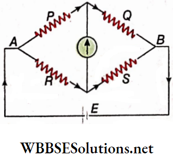
Example 2. Five resistances are connected. What is the effective resistance between points A and B?
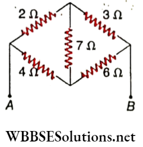
Solution:
⇒ \(\text { Here, } \frac{2 \Omega}{3 \Omega}=\frac{4 \Omega}{6 \Omega}\)
So, the circuit between points A and B is a balanced Wheatstone bridge. So no current flows through the resistance of 7Ω. In this condition to calculate the effective resistance, the resistance of 7Ω will be ignored.
Equivalent resistance of 2Ω and 3Ω = 2 + 3 = 5Ω
Equivalent resistance of 4Ω and 6Ω = 4 + 6 = 10Ω
Now at points A and B these 5Ω and 10Ω resistances are connected in parallel.
So, the effective resistance = \(\frac{5 \times 10}{5+10}=\frac{50}{15}=\frac{10}{3} \Omega\)
Examples of Kirchhoff’s Laws Applications
Example 3. In a Wheatstone bridge, a resistance and an unknown resistance are placed in the third arm and fourth arm respectively. Current through galvanometer becomes zero when the ratio of resistances of first and second arms is 3: 2. Find the value of unknown resistance.
Solution:
⇒ \(\text { Here, } R=15 \Omega \text { and } \frac{P}{Q}=\frac{3}{2}\)
since \(\frac{P}{Q}=\frac{R}{S} \quad\)
∴ \( S=R \cdot \frac{Q}{P}=15 \times \frac{2}{3}=10 \Omega\)
Example 4. The resistances of the four arms of a Wheatstone bridge are 100Ω, 10Ω, 300Ω, and 30Ω respectively. A battery of emf 1.5 V and negligible internal resistance is connected to the bridge. Calculate the current flowing through each resistance.
Solution:
Here, P = 100Ω,
Q = 10Ω, R = 300Ω, S = 30Ω and E = 1.5 V
Since, \(\frac{100}{10}=\frac{300}{30}\)
i.e., \(\frac{P}{Q}=\frac{R}{S}\), the bridge Is in a balanced condition.
∴ Current in the resistance P = current in the resistance Q
⇒ \(\frac{V_{A B}}{P+Q}=\frac{1.5}{100+10}=\frac{1.5}{110}\)
= 0.0136A
Again, current in the resistance R = current in the resistance S
⇒ \(\frac{V_{A B}}{R+S}=\frac{1.5}{300+30}=\frac{1.5}{330}\)
= 0.0045A
Class 12 Physics Circuit Analysis Notes
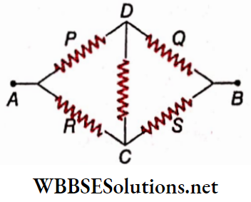
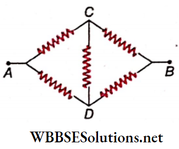
Example 5. Every resistance is of magnitude r. What is the equivalent resistance between A and B?
Solution:
The Wheatstone bridge circuit is the equivalent circuit.
Here, P = Q- R = S = r
∴ \(\frac{P}{Q}=\frac{R}{S}\)
i.e., the circuit is in a balanced condition. So for the calculation of equivalent resistance, the value of CD is of no use.
Now, resistance along the path ADB = r+ r = 2r and resistance along the path ACB = r+ r = 2r
Since ADB and ACB are connected in parallel, the equivalent resistance between the points A and B is
⇒ \(R^{\prime}=\frac{2 r \times 2 r}{2 r+2 r}=\frac{4 r^2}{4 r}=r\)
Real-Life Applications of Electrical Measurement
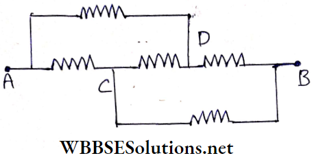
Example 6. Each resistance in the given circuit in is of value R. Calculate the equivalent resistance of the circuit with respect to the points A and JB.
Solution:
The equivalent circuit.
Now proceeding in the same way as done in Example 1, it can be shown that equivalent resistance =R.
Example 7. A coil of wire is kept in melting ice. Its resistance measured by a Wheatstone bridge is 5Ω. If the coil is heated to I00°C and another wire of resistance 100Ω is connected in parallel to it, the balanced condition of the bridge remains unchanged. Determine the temperature coefficient of resistance of the coil wire.
Solution:
If the resistance of the coil at 100°C is R, then the equivalent resistance of the parallel combination of R and 100Ω is 5Ω
∴ \(\frac{R \times 100}{R+100}=5 \quad\)
or, 95 R=500
or, \(R=\frac{100}{19} \Omega\)
Again, if or be the temperature coefficient of resistance of the wire of the coil, then
R = R0(l + αt)
or, \(\alpha=\frac{\frac{R}{R_0}-1}{t}=\frac{\frac{100}{19 \times 5}-1}{100}=\frac{5}{9500}\)
= 5.26 x 10⁻⁴ °C-1
WBCHSE Class 12 Physics Chapter 4 Notes
Example 8. An electrical circuit. Calculate the potential difference across the resistance 400Ω as will be measured by the voltmeter V of resistance 400Ω.
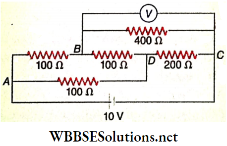
Solution:
The equivalent circuit.
The equivalent resistance between B and C = \(\frac{400 \times 400}{400+400}\)
= 200Ω
This is a Wheatstone bridge circuit, where
⇒ \(\frac{\text { resistance of the side } A B(P)}{\text { resistance of the side } B C(Q)}=\frac{100}{200}\)
= \(\frac{\text { resistance of side } A D(R)}{\text { resistance of side } D C(S)}\)
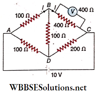
So, the bridge is in a balanced condition, i.e., no current flows in the arm BD. Under this condition the reading of the voltmeter, V is
⇒ \(V_B-V_C=I Q=\frac{V_A-V_C}{P+Q} \times Q\)
⇒ \(\frac{10}{100+200} \times 200=\frac{20}{3}\)
= 6.67V
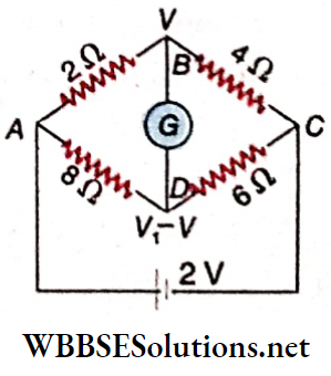
Example 9. ABCD is a Wheatstone bridge in which the resistance of the arms AB, BC, CD, and DA are respectively 2Ω,4Ω,6Ω, and 8&&. Points A and C are connected to the terminals of a cell of emf 2 V and have negligible internal resistance. Points B and D are connected to a galvanometer of resistance 50Ω. Using KirchhofFs laws find the current flowing through the galvanometer
Solution:
In the circuit of let VC = 0; then VA = 2V;
again, if VB = V1 and VB-VD = V, then VD=V1-V
Now, applying Kirchhoff’s 1st law at junction B, we get
⇒ \(\frac{V_1-2}{2}+\frac{V_1}{4}+\frac{V}{50}=0\)
or, \(\frac{50 V_1-100+25 V_1+2 V}{100}=0\)
or, 75V1 + 2V = 100…..(1)
Again applying Kirchhoff’s 1st law at junction D, we get
⇒ \(\frac{V_1-V-2}{8}+\frac{V_1-V}{6}+\frac{-V}{50}=0\)
or, \(\frac{75 V_1-75 V-150+100 V_1-100 V-12 V}{600}=0\)
or, 175V1 – 187V = 150…(2)
Doing (1) x 7- (2) X 3 we get
575 V = 250
or, \(V=\frac{250}{575} \mathrm{~V}\)
∴ \(I_G=\frac{V}{50}=\frac{250}{575 \times 50}=\frac{1}{115}\)
= 0.0087A
= 8.7mA
Example 10. We determine the value of the fourth resistance to be 8Ω with the help of a Wheatstone bridge with three known resistances 100Ω, 10Ω, and 80Ω respectively. If the emf of the cell and its internal resistance are 2 V and 1.1Ω respectively, find the current passing through the cell.
Solution:
The bridge is in a balanced condition because \(\frac{100}{10}=\frac{80}{8}\) galvanometer current is zero. In this case, the effective circuit. Total resistance of the circuit
⇒ \(R=1.1+\frac{(100+10)(80+8)}{(100+10)+(80+8)}\)
= \(1.1+\frac{110 \times 88}{198}\)
= 50Ω
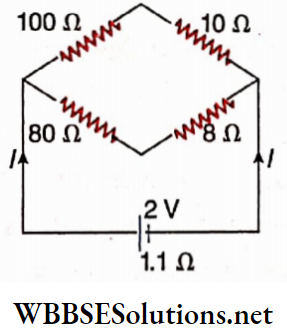
∴ Current through the cell, i.e., the main current of the circuit,
I = \(\frac{2}{50}\) = 0.04A
Metre Bridge:
It is another practical form of the Wheatstone Bridge. It also helps in measuring ordinary resistances very easily.
From the null condition of Wheatstone bridge, we have,
⇒ \(S=R \cdot \frac{Q}{P}\)…(1)
- In the meter bridge, the steps that are followed are mentioned below.
- The unknown resistance is placed in the fourth arm S.
- The magnitude of R, i.e., the resistance of the third arm is
kept constant. - By increasing or decreasing the ratio \(\frac{Q}{P}\), the bridge is brought to a balanced condition.
- Now by using equation (1) the unknown resistance S is calculated.
Description:
The meter bridge circuit. It consists of a one-metre-long thin uniform wire AB made of manganin or German silver. The wire is stretched and fixed to the two points a and f of two copper strips ab and fe and is placed along a meter scale M over a wooden board. There is another copper strip cd.
The gaps be and de is called the left gap and the right gap, respectively. A jockey J is connected to the midpoint of the copper strip cd through a galvanometer G and its sharp end touches the wire AB and can be moved along it when required.
A resistance box R is inserted in the left gap (third arm of the bridge). The resistance S to be determined is introduced in the right gap (fourth arm of the bridge). A cell E is connected to the bridge through a commutator C.
Working principle: An equivalent meter bridge circuit. Obviously, it is a Wheatstone bridge circuit.
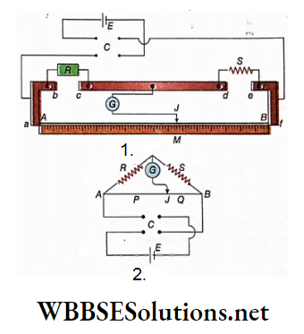
The direction of current through the wire AB can be reversed with the help of the commutator C. The left portion of the wire with respect to the position of the jockey is the first arm of the bridge and the right portion of the wire is the second arm, i.e., resistance of the portion AJ of the wire =P and resistance of the portion JB, of the wire = Q.
A suitable resistance R is introduced in ‘the resistance Now the moved along the wire till a null point is reached. At this balanced condition, let the length of AJ =l cm.
Length of JB = (100-l) cm [∵ AB = 1 m = 100 cm]
If ρ is the resistance per unit length of the wire then,
⇒ \(P=\rho l \text { and } Q=\rho(100-l)\)
∴ \(\frac{Q}{P}=\frac{100-l}{l} \text { and } S=R \cdot \frac{Q}{P}=R \cdot \frac{100-l}{l}\)…..(2)
Knowing l from the scale, S can be calculated from the equation (2). Taking different resistances from box R the experience is repeated.
Discussion:
Material of the wire: The wire of the meter bridge is generally made of alloys like manganin, German silver, etc. The resistance of a uniform manganin wire of length 1 m and diameter 0.5 mm is about 2Ω. The bridge becomes sensitive enough for this magnitude of resistance of the wire. On the other hand, the resistance of a copper wire of the same length and diameter is about 0.1Ω. The bridge is not at all sensitive if such a low resistance is used. For this reason, copper wire is never used in a meter bridge.
Thermoelectric effect:
The copper strips at the ends A and B of the wire come in contact with manganin or German silver. Now, if current passes through the junctions of two dissimilar metals, heat is evolved at one junction and is absorbed at the other due to the thermoelectric effect.
So, the wire AB does not remain in thermal equilibrium and hence its resistance per unit length, ρ is not uniform. Therefore, when we apply equation (2) to calculate the unknown resistance, an error occurs.
To remove this deficit is necessary to reverse the direction of the current through the wire AB. Then, heat will be absorbed at the end where it evolved originally and vice versa.
In this way, the thermal equilibrium of the wire AB will be maintained. To reverse the direction of current in the wire AB, a commutator C is used.
End error:
Though the resistance of the copper strips is very small, it is finitely non-zero.
The bridge wire is soldered at the two ends A and B with the copper strips. So some resistance exists in these two places.
The 0 and 100 cm marks of the meter stale (M) may not coincide accurately with the ends ll and B of the bridge wire. Hence it is assumed that some additional resistance exists at the two ends of the bridge wire.
This is called end resistance. So when we measure an unknown resistance, we face some end errors.
End correction: The end resistance may be assumed to be equivalent to the resistance of a certain length of the bridge wire. Suppose, the end resistance of end A = resistance of Ax cm of the bridge wire and end resistance of end B = resistance of Az cm of the bridge wire
i.e., resistance of l1 length of the bridge wire = resistance of (l1 + λ1) length and resistance of l2 length of the bridge wire = resistance of (l2 + λ2) length
In the position of the null point be l1 cm then we have from equation (2),
⇒ \(\frac{S}{R}=\frac{\left(100-l_1\right)+\lambda_2}{l_1+\lambda_1}\)…(3)
Now, by interchanging the position of R and S, if the null point is obtained at l2 cm, then we have
⇒ \(\frac{R}{S}=\frac{\left(100-l_2\right)+\lambda_2}{l_2+\lambda_1}\) …..(4)
If we use two known resistances R and S, we can find out λ1 and λ2 by solving equations (3) and (4). Next, using the values of λ1 and λ2, the unknown resistance can be measured accurately.
Position of the null point: The bridge becomes sensitive if the position of the null point lies between 40 cm and 60 cm of the bridge wire. But it is better to avoid the null point at 50 cm because in that case no change is observed in the reading of the null point on interchanging the positions of R and S.
Electrical Measurement Techniques Class 12 Notes
Kirchhoff’s Laws And Electrical Measurement Numerical Examples
Example 1. In a meter bridge experiment, a null point Is obtained at a length of 39.8 cm when a 2Ω resistance Is placed In the left gap and a 3Ω resistance in the right gap. If the two resistances are interchanged, the null point is obtained at 60.8 cm. Calculate the end errors of the bridge.
Solution:
Suppose, the resistance per unit length of the bridge wire = ρΩ.cm-1. End resistance of the left end of the bridge
= resistance λ1 of cm of the wire. End resistance of the right end of the bridge
= resistance of λ2 cm. of the wire. These two are the end errors of the bridge.
Therefore, iΩ be the position of the null point, then according to the relation \(\frac{P}{Q}=\frac{R}{S}\) we have,
⇒ \(\frac{R}{S}=\frac{\left(l+\lambda_1\right) \rho}{\left(100-l+\lambda_2\right) \rho}=\frac{l+\lambda_1}{100-l+\lambda_2}\)
In the first case,
R = 2Ω,S = 3Ω and l = 39.8 cm
∴ \(\frac{2}{3}=\frac{39.8+\lambda_1}{60.2+\lambda_2}\)
or, 3λ1 – 2λ2 = 1 ….(1)
Again, in the second case,
R = 3Ω,S = 2Ω and l = 60.8 cm
∴ \(\frac{3}{2}=\frac{60.8+\lambda_1}{39.2+\lambda_2}\)
or, 2λ1 – 3λ2 = -4 …(2)
Solving (1) and (2) we get,
λ1 = 2.2 and λ2 = 2.8
So, the left-end resistance and the right-end resistance of the bridge are equal to the resistances of 2.2 cm and 2.8 cm of the bridge wire respectively
Example 2. In the left gap of a meter bridge, there is a coil of copper and in the right gap, there is a fixed resistance. If the coil of copper is dipped in ice the balance point is obtained at 41.2 cm of the bridge wire. Next, the coil is taken off from ice and placed in a container of hot water. Now the balance point is shifted by a distance of 8.1 cm towards the right. What is the temperature of hot water? (Temperature coefficient of resistance of copper = 42.5 x 10⁻⁴ °C-1.)
Solution:
Suppose, fixed-resistance = R, the temperature coefficient of resistance of copper = aaa, the resistance of the coil at 0°C = R0, the position of the balance point = l0, the resistance of the coil at t°C = Rt, and the position of the balance point =l.
∴ Rt = R0(l + at)
According to the principle of the meter bridge,
In case of \(0^{\circ} \mathrm{C}, \frac{R_0}{R}=\frac{l_0}{100-l_0}\)….(1)
In case of \(t^{\circ} \mathrm{C}, \frac{R_0(1+\alpha t)}{R}=\frac{197}{100-l}\) …(2)
Dividing (2) by (1) we have,
⇒ \(1+\alpha t=\frac{l}{l_0} \times \frac{100-l_0}{100-l}\)
⇒ \(\frac{49.3}{41.2} \times \frac{100-41.2}{100-49.3} \cdot[l=41.2+8.1=49.3]\)
⇒ \(\frac{49.3}{41.2} \times \frac{58.8}{50.7}=1.388\)
∴ \(t^t=\frac{1.388-1}{\alpha}=\frac{0.388}{42.5 \times 10^{-4}}\)
= 91.3°C
Conceptual Overview of Circuit Analysis Using KCL and KVL
Example 3. In a meter bridge, the balance point is found to be at 40 cm from one end when the resistor at the end is 15Ω. Find the resistance on the other side.
Solution:
If p be the resistance per 1 cm length of the metre wire, then in the present case,
P = 40ρΩ, Q = (100-40)ρ = 60ρΩ, R = 15Ω,
S =?
In balance condition \(\frac{P}{Q}=\frac{R}{S}\)
or, \(S=R \frac{Q}{P}=15 \times \frac{60 \rho}{40 \rho}\)
= 22.5Ω
Example 4. In the circuit given, E1 = 6 V, E2 = 2 V, E3 = 3 V, C’ = 5μF, = 2R2 = 6Ω, R3 = 2R4 = 4Ω. Find the current in R3 and the energy stored in the capacitor
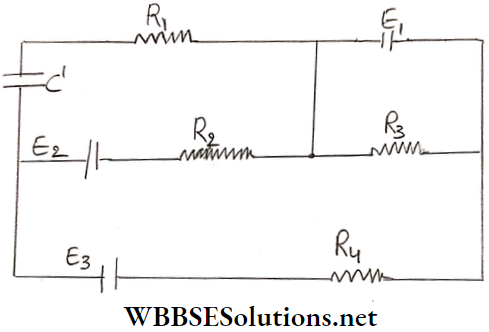
Solution:
Let the distribution of currents in the various branches be as shown below.
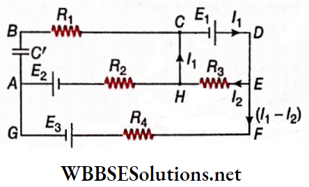
Considering the closed loop CDEHC
⇒ \(I_2 R_3=E_1 \quad \text { or, } 4 I_2=6 \quad \text { or, } I_2=1.5 \mathrm{~A}\)
∴ Current through the resistance = 1.5 A
Considering the closed-loop AHEFGA,
⇒ \(\left(I_1-I_2\right) \times R_2-I_2 R_3+\left(I_1-I_2\right) R_4=-E_2-E_3\)
or, \(\left(I_1-1.5\right) \times 3-1.5 \times 4+\left(I_1-1.5\right) \times 2=-2-3\)
∴ I1 = 1.7A
Let VA and VC be the potentials at points A and C respectively, As the current flows from point A to C along the path AHC,
VA = VC + potential drop across R2 + E2
or, VA-VC= (I1-I2)R2+E2
= (1.7- 1.5) X 3+ 2
∴ VA-VC = 2.6 V
Through branch ABC current = 0. Hence the potential difference across the capacitor is equal to the potential difference between the points A and C.
∴ Potential differences across the capacitor,
VA-VC = 2.6V
∴ Energy storedin the capacitor,
⇒ \(U=\frac{1}{2} C V^2=\frac{1}{2} \times 5 \times 10^{-6} \times(2.6)^2\)
= 1.69 x 10⁻⁵ J
Example 5. If the resistance X and Y. (X < Y) are placed in the two gaps of a meter bridge, a null point is obtained at a length of 20 cm. Keeping Y unchanged if a resistance 4X is placed in place of X what will be the position of the null point?
Solution:
In the first case, \(\frac{X}{Y}=\frac{20}{100-20}\)
or, Y = 4X
So, if resistance 4X is placed in place of X, the resistances of the two gaps will be equal, since Y = 4X.
Therefore, the null point will be in the middle of the bridge wire i.e., at 50 cm
Electrical Measurement Techniques Class 12 Notes
Example 6. The distance between the positions of two null points obtained in a meter bridge wire of length 100 cm, by interchanging a known resistance of 2.5Ω and an unknown resistance in the two gaps, is 28.6 cm. Find the value of the unknown resistance.
Solution:
In the first case, if the unknown resistance r is kept at the
left gap and resistance of 2.5Ω at the right gap, the position of null point l1.
∴ \(\frac{r}{2.5}=\frac{l_1}{100-l_1}\)…(1)
In the second case, after interchanging the resistances, the position of the null point l2
∴ \(\frac{2.5}{r}=\frac{l_2}{100-l_2}\)…(2)
According to the question,
l1-l2 = 28.6…(3)
By (1) x (2) we get,
⇒ \(1=\frac{l_1 l_2}{\left(100-l_1\right)\left(100-l_2\right)}\)
or, 104 – 100l1 – 100l2 + l1l2 = l1l2
or, l1 + l2 = 100….(4)
Solving equation (3) and (4),
l1 = 643
and l2 = 100-l1 = 35.7
∴ The value of the unknown resistance
⇒ \(r=2.5 \times \frac{l_1}{100-l_1}=2.5 \times \frac{64.3}{100-64.3}=4.5 \Omega\)
Kirchhoff’s Laws And Electrical Measurement Very Short Questions and Answers
Question 1. In which part of an electrical circuit can Kirchhoff’s law of
Answer: At the meeting points
Question 2. In which part of an electrical circuit can Kirchhoff’s law of voltage be applied?
Answer: At The Closed Loops
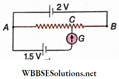
Question 3. If the potential of point C be 12 V, what will be the potential of the point D?
Answer: 3V
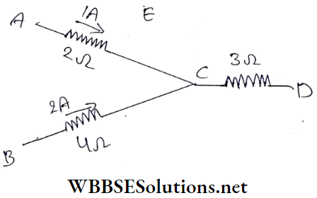
Question 4. At a junction of three wires, the inward currents through two of the wires are 1 A and 2 A. What is the inward current through the third wire?
Answer: -3 A
Question 5. AB = 1 m. What will be the length of the part AC for the null condition of the galvanometer?
Answer: 75cm
Question 6. Why do we prefer a potentiometer with a longer wire?
Answer: Proportional error in the recorded reading will be less
Question 7. What kind of cell should be used in a Wheatstone bridge circuit?
Answer: Leclanche cell
Question 8. Of battery and galvanometer segments which one should be closed first during the operation of a Wheatstone bridge circuit?
Answer: Battery
Question 9. The resistance of each of the four arms of a Wheatstone bridge is 10Ω and the resistance of the galvanometer is 500Ω. What is the equivalent resistance of the combination?
Answer: 10Ω
Question 10. The resistances in the left and the right gaps of a metre bridge circuit are 3Ω and 2Ω respectively. For what length of the bridge wire IN the null point found If there In no end error?
Answer: 60cm
Question 11. Keeping a resistance of 2Ω In the left gap of a metre bridge, an unknown resistance Is placed In the right gap and the null point is obtained at a distance of 40.0 cm. If no end error Is present, what will be the value of the unknown resistance?
Answer: 3Ω
Electrical Measurement Techniques Class 12 Notes
Kirchhoff’s Laws And Electrical Measurement Fill In The Blanks
1. Kirchhoff’s law of current expresses the principle of conservation of charge
2. With the help of a potentiometer, the emf of a cell can be measured accurately, in this experiment lost volt of the cell becomes zero
3. A battery of steady emf 2.0 V is connected across the two ends of a potentiometer wire. With the help of this arrangement, the emf of more than 2V of a cell can not be determined.
Kirchhoff’s Laws And Electrical Measurement Assertion Reason Type
Direction: These questions have Statement 1 and Statement 2. Of the four choices given below, choose the one that best describes the two statements.
- Statement 1 is true, Statement 2 is true; Statement 2 is a correct explanation for Statement 1.
- Statement 1 is true, Statement 2 is true; Statement 2 is not a correct explanation for Statement 1.
- Statement 1 is true, Statement 2 is false.
- Statement 1 is false, and Statement 2 is true.
Question 1.
Statement 1: A balance is obtained at the position of 40 cm on the meter wire, when 2Ω and 3Ω resistances are put in the left and right gaps respectively, of a meter bridge.
Statement 2: The balanced condition of a Wheatstone bridge is P/Q = R/S.
Answer: 1. Statement 1 is true, Statement 2 is true; Statement 2 is a correct explanation for Statement 1.
Question 2.
Statement 1: An alloy like manganin or German silver is used, instead of copper, as the material of the wire of a meter bridge.
Statement 2: The temperature coefficient of resistance is very low for alloys.
Answer: 2. Statement 1 is true, Statement 2 is true; Statement 2 is not a correct explanation for Statement 1.
Question 3.
Statement 1: A potentiometer arrangement is more suitable than a voltmeter arrangement for the accurate measurement of the emf of an electric cell.
Statement 2: It is possible to connect an electric cell in a potentiometer circuit in such a way that no current passes through the cell.
Answer: 1. Statement 1 is true, Statement 2 is true; Statement 2 is a correct explanation for Statement 1.
Question 4.
Statement 1: If the resistances of the first two arms P and Q of a balanced Wheatstone bridge are exchanged, the balanced condition is not disturbed.
Statement 2: The balanced condition of a Wheatstone bridge is independent of the resistance of the galvanometer used.
Answer: 4. Statement 1 is false, Statement 2 is true.
Question 5.
Statement 1: Kirchhoff’s voltage law indicates that the static field is conservative.
Statement 2: The potential difference between two points in a circuit does not depend on the path.
Answer: 1. Statement 1 is true, Statement 2 is true; Statement 2 is a correct explanation for Statement 1.
Question 6.
Statement 1: In the balanced Wheatstone bridge,
⇒ \(R_{A C}=\frac{(P+Q)(R+S)}{(P+Q+R+S)}\)
Statement 2: This is because B and D are at the same potential.
Answer: 2. Statement 1 is true, Statement 2 is true; Statement 2 is not a correct explanation for Statement 1.
Question 7.
Statement 1: In an electrical circuit the algebraic sum of currents meeting at a point is zero.
Statement 2: In the case of the flow of current in an electrical circuit total energy is conserved.
Answer: 2. Statement 1 is true, Statement 2 is true; Statement 2 is not a correct explanation for Statement 1.
Kirchhoff’s Laws And Electrical Measurement Match The Columns
Question 1. A balance is obtained at 25 cm of a meter bridge when resistances X and Y are placed in the left and the right gaps respectively. Then, during repetitions of the experiment, the left and the right gaps are filled respectively, with the resistances of column A. Column B shows the positions of, the balance points
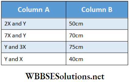
Answer: 1-D, 2-B, 3-A, 4-C
Question 2. Match the following two columns to specify the instrument to be used for the given electrical purposes
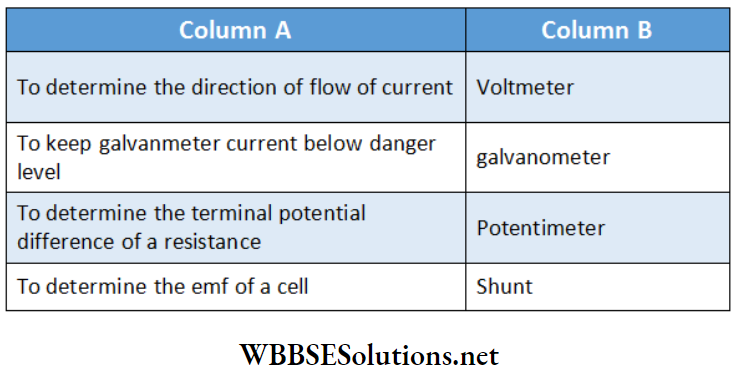
Answer: 1-B, 2-D, 3-A, 4-C