WBCHSE Class 12 Physics Capacitance Capacitance And Capacitor Capacitance
If a body is heated, its temperature rises. Similarly, the conductor is positively charged, and its potential increases if different materials are heated equally, their temperature rise is not equal because the thermal capacities of the bodies are different. Similarly, even if different conductors are charged equally, their increase in potential may not be equal. The potential of a conductor depends not only on the amount of charge possessed by it but also on its shape, surface area, nature of the surrounding medium, and presence of other conductors.
For a given conductor its potential is always proportional to its charge. If a conductor is charged with Q and as a result, its potential is raised by an amount V, then
Q ∝ V or, Q = CV
The proportionality constant C is known as the capacitance or capacity of the conductor. Its value depends on shape, surface area, nature of the surrounding medium, and presence of other conductors.
From equation (1) we have,
C = \(\frac{Q}{V}\)…(2)
i.e., capacitance = \(\frac{amount of charge}{rise of potential}\)
If V = 1, then C = Q.
Read and Learn More Class 12 Physics Notes
Definition: The capacitance or capacity of a conductor is defined as the charge required to raise its potential by unity.
Units of Capacitance:
In the CGS system:
In the CGS system, a unit of capacitance is esu of capacitance. In the above equation (2), if Q = 1 esu of charge and V = 1 esu of potential, then’ C = 1 esu of capacitance, i.e., if 1 esu of charge raises the potential of a conductorby1 esu, the capacitance of the conductor is defined as 1 esu. This unit is also known as statfarad (statF).
In SI: SI unit of capacitance is farad (F). It is the practical unit of capacitance. The capacitance of a conductor is said to be 1 farad if 1 coulomb of charge is required to raise the potential of the conductor by 1 volt.
Therefore, IF = \(\frac{1 \mathrm{C}}{1 \mathrm{~V}}\)
Since farad is a very large unit, smaller units like microfarad and picofarad are most frequently used as the unit of capacitance.
1 microfarad (μF) = 10-6 farad (F)
1 picofarad (pF) = 10-12 farad (F)
Relation between farad and esu of capacitance:
1C = 3 X 10⁹ esu of charge
IV = esu of potential
∴ \(1 \mathrm{~F}=\frac{1 \mathrm{C}}{1 \mathrm{~V}}=\frac{3 \times 10^9 \text { esu of charge }}{\frac{1}{300} \text { esu of potential }}\)
= 9 x 10¹¹ esu of capacitance or statF
1μF = 10-6F = 9 x 10 esu of capacitance
lpF = 10-12F = 0.9 esu of capacitance
Dimension of capacitance
⇒ \(C=\frac{Q}{V}=\frac{Q}{W / Q}=\frac{Q^2}{W}\)
∴ \([C]=\frac{\left.T^2\right|^2}{M L^2 T^{-2}}=M^{-1} L^{-2} T^4 I^2\)
WBBSE Class 12 Capacitance Notes
Capacitance And Capacitor Capacitance Numerical Examples
Example 1. The capacitance of a spherical conductor is 1μF and the charge on it is -10C. What is its potential in the air?
Solution:
We know, V = 2;
here C = 1μF = 10-6F,
Q = -10C
∴ \(V=\frac{-10}{10^{-6}}=-10^7 \mathrm{~V}\)
Example 2. The potential of a conductor having 40 esu of capacitance is raised by 10 esu. What is the charge on the conductor? How much charge is to be given to another conductor, having capacitance three times that of the first conductor, to raise its potential three times that of the first one?
Solution:
Charge given to the first conductor,
Q1 = C1V1
= 40 x 10
= 400 esu of charge
The capacitance of the second conductor,
C2 = 3C1
= 3 x 40
= 120 esu of capacitance
The potential rise of the second conductor,
V2 = 3 x 10
= 30 esu of potential
Charge to be given to the second conductor,
Q2 = C2V2
= 120 x 30
= 3600 esu of charge
Factors Affecting Capacitance of a Conductor:
A conductor, at a potential V and having a charge Q, has a capacitance, C = \(\frac{Q}{V}\).
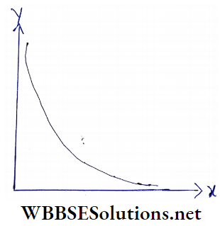
For constant Q, \(C \propto \frac{1}{V}\) Hence, the factors affecting V also affect the value of C of a conductor. The value of the capacitance of a conductor depends on the following factors.
- Surface area and shape of the conductor,
- Nature of the surrounding medium
- Presence of other conductors (especially earthed ones).
WBCHSE Class 12 Physics Capacitance Notes Surface area and shape of the conductor:
A conductor of greater size, i.e., a larger surface area has larger capacitance. The potential of a conductor decreases with the increase of its surface area and hence its capacitance increases.
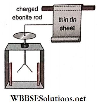
Experiment:
A thin tin sheet is suspended from a charged ebonite rod. At the bottom of the sheet, a heavy metal rod is attached. This rod keeps the sheet stretched.
The tin sheet Is connected to the disc of a gold-leaf electroscope by a metal wire. If the sheet Is given a definite amount of charge, the leaves of the gold-leaf electroscope spread apart.
The divergence of the leaves indicates the potential of the sheet. NowIf the tin sheet is rolled up to some extent with the help of the ebonite rod, the divergence of the leaves of the electroscope will Increase.
It indicates that the potential of the sheet has increased, So, the charge of the sheet remains constant, and its capacitance decreases.
If the of the tin sheet is increased, the divergence of the leaves decreases, i.e., the potential of the sheet decreases and its capacitance increases. So, the capacitance of a conductor depends on its surface area.
If the experiment is performed with conductors of the same surface area but of different shapes, it will be found that the spreading of the leaves of the gold-leaf electroscope are different So capacitance of a conductor also depends on its shape.
Nature of the surrounding medium:
If the conductor is surrounded by some dielectric medium other than air, the capacitance of the conductor increases. The effect increases with the increase of the dielectric constant of the medium.
Experiment:
A charged metal sheet A placed on an insulating stand is connected to the disc of an uncharged gold-leaf electroscope. The divergence of the leaves of the electroscope is observed. The amount of deflection indicates the potential of the metal sheet.
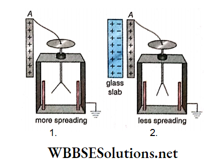
Now a dielectric slab, say a thick glass slab, is brought slowly near sheet A. It is found that the spreading of the leaves diminishes. So, the potential of A has decreased, i.e., its capacitance has increased.
Again if the dielectric slab is removed from the vicinity of sheet A, the electroscope leaves will spread out to the same extent as earlier.
In this case, the dielectric medium is polarised from induction due to the metal sheet A. So opposite charges are developed on the two sides of the glass slab.
Induced negative charge reduces the potential of sheet A and positive charge raises the potential of A.
However, due to the close proximity of the negative charge, its effect on sheet A predominates. So as a whole, the potential of sheet A diminishes a little, and hence its capacitance increases.
WBCHSE Class 12 Physics Capacitance Notes
Presence of other conductors:
The capacitance of a conductor depends on the presence of other conductors near it. If an uncharged conductor is present in the vicinity of the charged conductor under test, its capacitance increases. This effect becomes pronounced if the neighboring conductor is earthed.
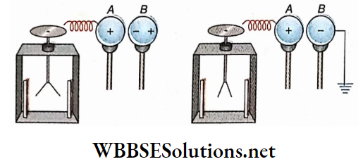
Experiment:
If a positively charged conductor A placed on an insulating stand is connected to the disc of an uncharged gold-leaf electroscope, the leaves of the electroscope spread out. The amount of divergence indicates the potential of conductor A.
Now another uncharged conductor B placed on an insulating stand is brought near A, it will be found that the divergence of the leaves diminishes a little. So, the potential of A has decreased a little.
If conductor B is removed, the leaves spread to the same extent as earlier. From this, it is understood that if B is brought near A, the potential of A diminishes, and its capacitance increases.
The reason is that an induced negative charge is developed at the nearer end and a positive charge at the far end of B due to the inducing charge of A.
The induced negative charge reduces the potential of A and the induced positive charge enhances its potential. But due to the proximity of the negative charge its effect on A predominates. So as a whole, the potential of conductor A diminishes a little, and hence its capacitance increases.
Now if conductor B is earthed, it will be found that the divergence of the leaves decreases considerably. This proves that the potential of conductor A is highly reduced.
If conductor B is removed from the vicinity of the coil now ductor A, the leaves of the electroscope will spread out to the same extent as earlier. So it is proved that if conductor B is earthed, the potential of conductor A diminishes a lot and hence its capacitance increases to a large extent.
The reason is that, if B is connected to the earth, the induced positive charge being free charge moves to the earth. Under this condition, due to the presence of only a negative charge in B, the potential of A diminishes a lot and hence its capacitance increases to a large extent.
The capacitance of a Spherical Conductor:
Let us consider a spherical conductor of radius R charged with Q’ amount of charge. The charge Q is uniformly distributed over the surface of the sphere. Potential at the surface of the sphere, as we know, is the same as that produced by an isolated point charge Q placed at the center of the sphere.
The potential of the sphere is given by,
⇒ \(V=\frac{1}{4 \pi \epsilon_0} \cdot \frac{Q}{R}\) [∈0 = permittivity of air or vacuum]
∴ The capacitance of the sphere,
⇒ \(C=\frac{Q}{V}=4 \pi \epsilon_0 R\)
We know, \(\frac{1}{4 \pi \epsilon_0}=9 \times 10^9 \mathrm{~N} \cdot \mathrm{m}^2 \cdot \mathrm{C}^{-2}\)
So, in vacuum or air, the capacitance of the sphere,
⇒ \(C=\frac{R}{9 \times 10^9} \text { farad }\)
In CGS system, replacing \(\epsilon_0 \text { by } \frac{1}{4 \pi}\), we have, C = R.
Hence the capacitance in the CGS unit of a spherical conductor placed in the air (or vacuum) is numerically equal to its radius in centimeters. For this reason, the capacitance CGSunit is sometimes expressed in centimeters.
Unit of ∈0: From the relation C = 4π∈0R,we have,
⇒ \(\epsilon_0=\frac{C}{4 \pi R}\)
So, the unit of ∈0
⇒ \(=\frac{\text { unit of } C}{\text { unit of } R}=\frac{\mathrm{F}}{\mathrm{m}}=\text { farad } / \text { metre }\left(\mathrm{F} \cdot \mathrm{m}^{-1}\right)\)
Using this simpler unit, we may write,
= 8.854 x 10⁻²¹ F.m-1
That this unit F m-1 is identical to the unit C².N-1.m-2 of ∈0, used earlier, is shown here
⇒ \(\mathrm{F} \cdot \mathrm{m}^{-1}=\frac{\mathrm{F}}{\mathrm{m}}=\frac{\mathrm{C}}{\mathrm{V} \cdot \mathrm{m}}=\frac{\mathrm{C}}{\frac{\mathrm{J}}{\mathrm{C}} \cdot \mathrm{m}}=\frac{\mathrm{C}^2}{\mathrm{~J} \cdot \mathrm{m}}\)
⇒ \(\frac{\mathrm{C}^2}{(\mathrm{~N} \cdot \mathrm{m}) \cdot \mathrm{m}}=\frac{\mathrm{C}^2}{\mathrm{~N} \cdot \mathrm{m}^2}=\mathrm{C}^2 \cdot \mathrm{N}^{-1} \cdot \mathrm{m}^{-2}\)
Class 12 Physics Capacitor Notes
Capacitance And Capacitor Factors Affecting Capacitance of a Conductor Numerical Examples
Example 1. The radius of the__earth is 6400km. Determine its capacitance in μF.
Solution:
The radius of the earth = 6400 km = 6400 x 10³ m.
Capacitance, \(C=4 \pi \epsilon_0 R=\frac{1}{9 \times 10^9} \times 6400 \times 10^3\)
⇒ \(=\frac{64}{9} \times 10^{-4}=\frac{6400}{9} \times 10^{-6} \mathrm{~F}\)
= 711.1μF
Example 2. A metal sphere has a diameter of 1 m. What will be the amount of charge required to raise its potential by 2.7 x 10⁶ V?
Solution:
Radius, R = \(\frac{1}{2}\) = 0.5 m;
⇒ \(C=4 \pi \epsilon_0 R=\frac{1}{9 \times 10^9} \times 0.5=\frac{0.5}{9 \times 10^9} \mathrm{~F}\)
∴ The amount of charge required,
⇒ \(Q=C V=\frac{0.5}{9 \times 10^9} \times\left(2.7 \times 10^6\right)\)
= 1.5 X 10-4
= 150 X 10-6 C
= 150μC
Example 3. Is it possible for a metal sphere with a radius of 1 cm to hold a charge of IC?
Solution:
Radius, r = 1 cm = 0.01 m
So, capacitance of the sphere
⇒ \(C=4 \pi \epsilon_0 r=\frac{1}{9 \times 10^9} \times 0.01=\frac{1}{9} \times 10^{-11} \mathrm{~F}\)
∴ The potential of the sphere,
⇒ \(V=\frac{Q}{C}=\frac{1}{\frac{1}{9} \times 10^{-11}}=9 \times 10^{11} \mathrm{~V}\)
At this very high potential, the sphere will discharge in the sureo rounding air, i.e., it will not be able to hold the charge of 1 C.
Practice Problems on Capacitance for Class 12
Example 4. SI The diameter of the spherical liquid drop is 2mm and its charge is 5 x 10⁻⁶ esu.
- What is the potential and its surface?
- If two such liquid drops coalesce to form a bigger drop, what will be the potential on its surface?
Solution:
1. In the CGS system, the radius of the spherical conductor = its capacitance (numerically).
∴ The capacitance of the spherical liquid drop,
C = 0.1 statF [∵ Radius = 1mm = 0.1 cm ]
∴ Potential on the surface of the liquid drop,
⇒ \(V=\frac{Q}{C}=\frac{5 \times 10^{-6}}{0.1}=5 \times 10^{-5} \mathrm{statV}\)
= 5 x 10-5 x 300 V
= 0.015 V
2. Let the radius of the bigger drop be R.
According to the question,
⇒\(\frac{4}{3} \pi R^3=2 \times \frac{4}{3} \pi(0.1)^3\)
or, \(R^3=2 \times(0.1)^3\)
or, \(R=0.1 \times 2^{\frac{1}{3}}\)
= 0.1 x 1.26
= 0.126 cm
Total charge,
Q = 2 x 5 x 10-6
= 10~5 esu of charge.
∴ Potential on the surface of the bigger liquid drop,
⇒ \(V=\frac{Q}{C}=\frac{10^{-5}}{0.126}\)
= 7.94 x 10-5 x 300 statV
= 7.94 x 10-5 x 300 V
= 0.0238 V
Class 12 Physics Capacitor Notes
Capacitance And Capacitor Potential Energy Of A Charged Conductor
A certain amount of work has to be done in order to charge a conductor. The energy spent for doing that work remains stored in the charged conductor as potential energy. Essentially, the electric field of the conductor stores this energy.
Calculation:
Let a conductor be charged with Q and let its capacitance be C. The potential of the conductor is V. During charging we assume that the whole amount of charge is not given to the conductor at a time, rather it is charged gradually.
At first, the charge of the conductor is zero so its potential is also zero. Gradually its potential increases due to the accumulation of charges. So at the time of charging the conductor has no particular potential. Its potential becomes V when its charge is Q.
Initial potential = 0; final potential = V
Average of these potentials = \(\frac{0+V}{2}=\frac{V}{2}\)
Therefore, work done = average potential x charge
⇒ \(\frac{V}{2} \times Q=\frac{1}{2} Q V=\frac{1}{2} C V \cdot V\) [∵ Q = CV]
⇒ \(\frac{1}{2} C V^2\)
= \(\frac{1}{2} C \times\left(\frac{Q}{C}\right)^2\)
= \(\frac{1}{2} \cdot \frac{Q^2}{C}\)
This work is stored in the charged conductor as potential energy.
∴ The potential energy of a charged conductor
⇒ \(\frac{1}{2} Q V\)
= \(\frac{1}{2} C V^2\)
= \(\frac{1}{2} \frac{Q^2}{C}\)
If C, V, and Q are expressed in esu, the unit of potential energy will be erg. Again C, V, and Q are expressed in farad, volt, and coulomb, respectively, the unit of potential energy will be joule.
Derivation using calculus: Let at any moment the charge on the conductor be q and its potential be v.
Evidently, q = Cv
When a charge dq is given to the conductor, the work done against the repulsive force due to potential v is given by,
⇒ \(d W=v d q=\frac{q}{C} d q\)
Hence the total work done to impart Q amount of charge is,
⇒ \(W=\int d W=\int_0^Q \frac{q}{C} d q=\frac{1}{2} \frac{Q^2}{C}=\frac{1}{2} C V^2=\frac{1}{2} Q V\)
This work is stored as potential energy in the charged conductor.
Capacitance And Capacitor Distribution Of Charge Between Two Conductors
Two conductors at the same potential:
Let us consider two insulated uncharged conductors A and B of capacitances C1 and C2, respectively. They are connected by a fine metal wire. Under this condition, if a charge Q is given to this combination, it will be distributed between the two conductors.
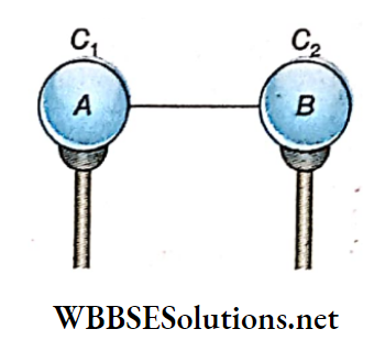
Let us consider that conductor A has obtained a charge Q1 and conductor B a charge Q2 As the two conductors are connected to each other, they have the same potential. Let their common potential be V.
Q = Q1 + Q2
and \(V=\frac{Q_1}{C_1}\)
= \(\frac{Q_2}{C_2}\)
= \(\frac{Q_1+Q_2}{C_1+C_2}\)
= \(\frac{Q}{C_1+C_2}\)
⇒ \(\left.\begin{array}{ll}
∴ & Q_1=C_1 V=Q \cdot \frac{C_1}{C_1+C_2} \\
\text { and } & Q_2=C_2 V=Q \cdot \frac{C_2}{C_1+C_2}
\end{array}\right\}\)…(1)
Again, \(\frac{Q_1}{Q_2}=\frac{C_1}{C_2}\)….(2)
Therefore, a charge on each conductor is proportional to its capacitance. If the two conductors have the same capacitance, the given charge will be shared equally between them. If they have radii r1 cm and r2 cm, then C1 = r1 and C2 = r2 (in the CGS system).
Short Notes on Electrostatic Potential and Capacitance
In that case,
⇒ \(\left.\begin{array}{l}
Q_1=Q \cdot \frac{r_1}{r_1+r_2} \\
Q_2=Q \cdot \frac{r_2}{r_1+r_2}
\end{array}\right\}\)….(3)
∴ \(\frac{Q_1}{Q_2}=\frac{r_1}{r_2}\)…(4)
Therefore, the charge on each spherical conductor is proportional to its radius.
We know that the surface density of charge on the surface of a charge is the same everywhere.
If σ1 and σ2 be the surface densities of charge of the two conductors, then
⇒ \(\sigma_1=\frac{Q_1}{4 \pi r_1^2} \text { and } \sigma_2=\frac{Q_2}{4 \pi r_2^2}\)
∴ \(\frac{\sigma_1}{\sigma_2}=\frac{Q_1}{Q_2} \cdot \frac{r_2^2}{r_1^2}=\frac{r_1}{r_2} \times \frac{r_2^2}{r_1^2}=\frac{r_2}{r_1}\)…(5)
Therefore, the surface density of the charge of a spherical conductor is inversely proportional to its radius.
Two conductors initially at different potentials:
Let us consider two insulated conductors A and B. They have capacitances C1 and C2 and they are given charges Q1 and Q2 separately.
So under this condition,
potential of the conductor A, \(V_1=\frac{Q_1}{C_1} \text { or, } Q_1=C_1 V_1\)
and potential of the conductor B, \(V_2=\frac{Q_2}{C_2} \text { or, } Q_2=C_2 V_2\)
∴ The total charge of the conductors,
Q = Q1 + Q2
= C1V1 + C2V2…(6)
If the two conductors are connected by a thin metal wire, a positive charge will flow from the conductor at a higher potential to that at a lower potential and this flow of charge will continue till their potentials become equal.
Suppose, V1 > V2; then a charge will flow from A to B. Let V be the common potential after connection. During this flow of charge, the total charge of the system remains constant.
So, total charge before connection = total charge after connection
i.e„ Q = C1V1 + C2V2
= C1V + C2V
= (C1 + C2)V
or, \(V=\frac{C_1 V_1+C_2 V_2}{C_1+C_2}\)….(7)
After connection, if A and B contain charges q x and q2 respectively, then
⇒ \(\left.\begin{array}{l}
q_1=C_1 V=C_1 \cdot \frac{C_1 V_1+C_2 V_2}{C_1+C_2}=\frac{C_1}{C_1+C_2} \cdot Q \\
q_2=C_2 V=C_2 \cdot \frac{C_1 V_1+C_2 V_2}{C_1+C_2}=\frac{C_2}{C_1+C_2} \cdot Q
\end{array}\right\}\)….(8)
As V1 > V2, the charge lost by A,
q’1 =C1V1-C1V = C1(V1-V)
⇒ \(C_1\left(V_1-\frac{C_1 V_1+C_2 V_2}{C_1+C_2}\right)\)
or, \(q_1^{\prime}=\frac{C_1 C_2\left(V_1-V_2\right)}{C_1+C_2}\)….(9)
Again, the charge gained by B,
⇒ \(q_2^{\prime}=C_2 V-C_2 V_2=C_2\left(\frac{C_1 V_1+C_2 V_2}{C_1+C_2}-V_2\right)\)
or, \(q_2^{\prime}=\frac{C_1 C_2\left(V_1-V_2\right)}{C_1+C_2}\)…..(10)
From equations (9) and (10) we get, q1 = q2, i.e., the charge gained by conductor B is equal to that lost by conductor A.
Loss of energy due to sharing of charge:
Before connection, the total energy of the two conductors
⇒ \(\frac{1}{2} C_1 V_1^2+\frac{1}{2} C_2 V_2^2\)
After connection, the total energy of them
⇒ \(\frac{1}{2} C_1 V^2+\frac{1}{2} C_2 V^2=\frac{1}{2}\left(C_1+C_2\right) V^2\)
⇒ \(\frac{1}{2}\left(C_1+C_2\right) \cdot\left(\frac{C_1 V_1+C_2 V_2}{C_1+C_2}\right)^2\)
⇒ \(\frac{1}{2} \cdot \frac{\left(C_1 V_1+C_2 V_2\right)^2}{C_1+C_2}\)
Therefore, loss of energy due to the sharing of charge
⇒ \(\frac{1}{2} C_1 V_1^2+\frac{1}{2} C_2 V_2^2-\frac{1}{2} \cdot \frac{\left(C_1 V_1+C_2 V_2\right)^2}{C_1+C_2}\)
⇒ \(\frac{1}{2} C_1 V_1^2+\frac{1}{2} C_2 V_2^2-\frac{1}{2} \cdot \frac{\left(C_1 V_1+C_2 V_2\right)^2}{C_1+C_2}\)
⇒ \(\frac{1}{2} \cdot \frac{C_1 C_2}{C_1+C_2} \times\left(V_1-V_2\right)^2\)….(11)
Now, C1 and C2 are both positive quantities, and (V1 – V2)², being a perfect square, is also positive. So, the relation (11) is positive.
Hence, there is always a loss of energy in the electric field of the conductors due to the sharing of charges.
According to the law of conservation of energy, this loss of energy must be converted to some other form, usually as heat in the connecting wire. This Joss is partly converted into light and sound in addition to heat if sparkling occurs.
Capacitance And Capacitor Distribution Of Charge Between Two Conductor Numerical Examples
Example 1. A conductor of capacity 4 units, charged with 100 units of positive charge is connected to another conductor of capacity 2 units, charged with 20 units of negative charge. What is the change In the potential of each conductor? What will be the charges for each of them after the connection?
Solution:
Capacity of the first conductor; C1 = 4 units; charge, Q1 = 100 units.
∴ \(\text { Potential, } V_1=\frac{Q_1}{C_1}\)
= \(\frac{100}{4}\)
= 25units
Capacity of the second conductor C2 = 2 units; charge, Q2 = -20 units.
∴ \(\text { Potential, } V_2=\frac{Q_2}{C_2}\)
= \(\frac{-20}{2}\)
= -10 units
After connection, suppose, the common potential of the two conductors becomes equal to V.
∴ \(V=\frac{Q_1+Q_2}{C_1+C_2}\)
= \(\frac{100-20}{4+2}\)
= \(\frac{80}{6}\)
= \(\frac{40}{3}\)
= 13.33 units
So, the change of potential of the first conductor
= 25-13.33
= 11.67 units
The change of potential of the second conductor
= 13.33- (-10)
= 2333 units
Residual charge in the first conductor after connection,
q1 = C1V
= 4 x \(\frac{40}{3}\)
= 5333 units
Residual charge in the second conductor after connection,
q2 = C2V
= 2 x \(\frac{40}{3}\)
= 26.67 units
Real-Life Applications of Capacitors
Example 2. An insulated metallic vessel full of water Is charged with a potential of 3V. Drops of water are trickling from an orifice at the bottom of the vessel What is the amount of charge contained In each spherical drop of radius 1mm?
Solution:
Potential of the metal vessel full of water, V = 3 V Radius of a water drop, R = 1 mm = 10-3m
∴ The capacitance of the water drop,
⇒ \(C=4 \pi \epsilon_0 \mathrm{R}=\frac{10^{-3}}{9 \times 10^9}=\frac{1}{9} \times 10^{-12} \mathrm{~F}\)
∴ Charge of each water drop,
⇒ \(Q=C V=\frac{1}{9} \times 10^{-12} \times 3=3.3 \times 10^{-13} \mathrm{C}\)
Example 3. The radii of two insulated metal spheres are 5 cm and 10 cm. They are charged up to potentials of 10 esu and 15 esu, respectively. If the two spheres are connected with one another, what will be the loss of energy?
Solution:
The radius of the first sphere = 5 cm
Capacitance, C1 = 5 statF
and potential, V1 = 10 statV
Charge, Q1 = C1V1
= 5 x 10
= 50 state
The radius of the second sphere = 10 cm
∴ Capacitance, C2 = 10 statF
and potential, V2 = 15 statV
Charge, Q2 = C2V2
= 10 x 15
= 150 statC
The total charge of the two spheres,
Q = Q1 + Q2
= 50 + 150
= 200 statC
Equivalent capacitance of the combination of two spheres,
C = C1 + C2
= 5 + 10
= 15 statF
If V is the common potential of the two spheres after connection, then
⇒ \(V=\frac{\text { total charge of the two spheres }}{\text { total capacitance of the two spheres }}\)
⇒ \(\frac{200}{15}\)
= \(\frac{40}{3} \mathrm{statV}\)
The total energy of the two spheres before connection,
⇒ \(E_1=\frac{1}{2} C_1 V_1^2+\frac{1}{2} C_2 V_2^2\)
⇒ \(\frac{1}{2}\left[5 \times(10)^2+10 \times(15)^2\right]\)
= 1375 erg.
The total energy of the two spheres after connection,
⇒ \(E_2=\frac{1}{2} C V^2=\frac{1}{2} \times 15 \times\left(\frac{40}{3}\right)^2\)
= 1333.33 erg
∴ Loss of energy due to connection
= 1375-1333.33
= 41.67 erg
Example 4. A metal sphere of radius 10 cm is charged up to a potential of 80 esu. After sharing its charge with another sphere, their common potential becomes 20 esu. What is the radius of the second sphere?
Solution:
The radius of the first sphere = 10 cm
∴ Capacitance C1 = 10 statF
and potential, = 80 statV
∴ Charge, Q1 = C1V1
= 10 x 80
= 800 state
After connection, the common potential, V = 20 statV
∴ \(V=\frac{\text { total charge of the two spheres }}{\text { equivalent capacitance of the two spheres }}\)
or, \(20=\frac{800}{10+C_2}\left[C_2=\text { capacitance of the second sphere }\right]\)
or, 10+ C2 = 40
or, C2 = 30 statF
Example 5. One thousand similar electrified raindrops merge into a single one so that their total charge remains unchanged. Find the change in the total electrostatic energy of the drops, assuming that all the drops are spherical and the small drops were initially at large distances from one another
Solution:
Suppose, each drop of radius r contains a charge Q.
∴ Capacitance, C = r
and energy, \(E_1=\frac{1}{2} \cdot \frac{Q^2}{C}=\frac{Q^2}{2 r}\)
The total energy of 1000 drops,
⇒ \(E=1000 E_1=\frac{500 Q^2}{r}\)
If R is the radius of the large drop then,
⇒ \(\frac{4}{3} \pi R^3=1000 \times \frac{4}{3} \pi r^3\)
or, R = 10r
Charge of the large drop = 1000 Q.
∴ The energy of the large drop,
⇒ \(E_2=\frac{1}{2} \cdot \frac{(1000 Q)^2}{R}\)
= \(\frac{5 \times 10^5 Q^2}{10 r}\)
= \(\frac{5 \times 10^4 Q^2}{r}\)
∴ \(\frac{E_2}{E}=\frac{5 \times 10^4}{500}=100\)
or, E2 = 100E
∴ Change in electrostatic energy of the drops
E2-E = 100E-E
= 99E
= 99 x initial energy
Example 6. Two equally charged soap bubbles of equal volume join together to form a large bubble. If each small bubble had a potential V, find the potential of the result
Solution:
Let the radius of each small bubble be r, the charge be Q, and the radius of the large bubble be R.
∴ \(\frac{4}{3} \pi R^3=2 \times \frac{4}{3} \pi r^3 \text { or, } R=2^{1 / 3} \cdot r\)
The potential of each small bubble,
V = \(\frac{Q}{r}\)
or, Q = Vr
∴ The potential of the large bubble
⇒ \(\frac{\text { total charge }}{\text { radius }}\)
⇒ \(\frac{2 Q}{R}\)
= \(\frac{2 V r}{2^{1 / 3} r}\)
= \(2^{2 / 3} V\)
Example 7. Eight spherical liquid drops join to form a large drop. The diameter of each drop is 2 mm and the charge 5μ statC. What is the potential on the surface of the large drop?
Solution:
Radius of a small drop, r = 1 mm =0.1 cm
Suppose, the radius of the large drop is R.
∴ \(\frac{4}{3} \pi R^3=8 \times \frac{4}{3} \pi r^3\)
or, R = 2r
= 2 x 0.1
= 0.2 cm
∴ The capacitance of large drop, C = R = 0.2 statF
The total charge of the small drops,
Q = 8 X 5
= 40μstatC
= 40 X 10-6 statC
∴ Potential on the surface of the large drop,
⇒ \(V=\frac{Q}{C}=\frac{40 \times 10^{-6}}{0.2} \text { statV }\)
= 2 X 10-4 x 300 V
= 0.06 V
Example 8. The ratio of the capacitances of two conductors A and B is 2: 3. The conductor A gains a certain amount of charge and shares it with B. Compare the initial energy of A with the total energy of A and B.
Solution:
Let the capacitance of the conductor A be 2C and that of the conductor B be 3C.
The amount of charge gained by A is Q.
Let the common potential of A and B after sharing of charge be V
∴ \(V=\frac{Q}{2 C+3 C}\)
= \(\frac{Q}{5 C}\)
The energy of the conductor A before sharing of charge,
⇒ \(E_A=\frac{1}{2} \cdot \frac{Q^2}{2 C}\)
= \(\frac{Q^2}{4 C}\)
Total energy of the conductors A and B after sharing the charge,
⇒ \(E_A=\frac{1}{2} \cdot \frac{Q^2}{2 C}\)
= \(\frac{Q^2}{4 C}\)
∴ The required ratio = \(\frac{E_A}{E}\)
= \(\frac{\frac{Q^2}{4 C}}{\frac{Q^2}{10 C}}\)
= \(\frac{5}{2}\)
Example 9. Each of the 27 identical mercury drops is charged to a potential of 10V. If the drops coalesce to form a big drop, what will be its potential? Calculate the ratio of the energy of the big drop to that of a small drop.
Solution:
Let the radius of each small drop be r.
∴ Capacitance, C1 = 4π∈0r
∴ Charge of each small drop, q = C1V1
= 10C1
∴ Total charge, Q = 27q = 27 x 10C1
= 270C1
If R is the radius of the big drop, then according to the question,
⇒ \(\frac{4}{3} \pi R^3=27 \times \frac{4}{3} \pi r^3 \text { or, } R=3 r\)
∴ The capacitance of the big drop,
C2 = 4π∈0.3r = 3C1
∴ The potential of the big drop,
⇒ \(V_2=\frac{Q}{C_2}=\frac{270 C_1}{3 C_1}=90 \mathrm{~V}\)
The energy of a small drop,
⇒ \(E_1=\frac{1}{2} C_1 V_1^2=\frac{1}{2} \times C_1 \times(10)^2\)
The energy of the big drop,
⇒ \(E_2=\frac{1}{2} C_2 V_2^2=\frac{1}{2} \times 3 C_1 \times(90)^2\)
∴ \(\frac{E_2}{E_1}=\frac{3 C_1}{C_1} \times \frac{(90)^2}{(10)^2}=\frac{243}{1}\)
∴ E2: E1 = 243: 1
Example 10. Charges of 10-2 C and 5 x 10-2.C are put on two metal spheres of radii 1 cm and 2 cm respectively. If they are connected with a metal wire, what will be the final charge on the smaller sphere?
Solution:
Here, the radius of the first sphere, R% = 1 cm = 0.01 m, and the radius of the second sphere, R2 = 2 cm = 0.02 m.
∴ The capacitance of the first sphere, C1 = 4π∈0R1
and capacitance of the second sphere, C2 = 4π∈0R2
The total amount of charge before and after connection,
Q1 + Q2 = Q
= (C1 + C2) V [V = common potential]
∴ \(\dot{V}=\frac{Q_1+Q_2}{C_1+C_2}\)
The final charge on the smaller (first) sphere,
⇒ \(q_1=C_1 V=C_1 \frac{Q_1+Q_2}{C_1+C_2}\) [Given, Q1 = 10-2C and Q2 = 5 x 10⁻²C]
⇒ \(4 \pi \epsilon_0 R_1 \times \frac{10^{-2}+5 \times 10^{-2}}{4 \pi \epsilon_0 R_1+4 \pi \epsilon_0 R_2}\)
⇒ \(R_1 \times \frac{6 \times 10^{-2}}{R_1+R_2}\)
= \(0.01 \times \frac{6 \times 10^{-2}}{0.01+0.02}\)
= 0.02C
Example 11. The capacitance and potential, respectively, of conductor A are 10 units and 50 units; those of conductor B are, respectively, 5 units and 65 units. Find out the charges on the two conductors after they
Solution:
Initially, the charge on conductor A,
Q2 = C1V1
= 10 x 50
= 500 unit
and charge on conductor B,
Q2 = C2V2
= 5 x 65
= 325 unit
The common potential after the two conductors are connected,
⇒ \(V=\frac{Q_1+Q_2}{C_1+C_2}=\frac{500+325}{10+5}=\frac{825}{15}\)
= 55 unit
Now, charge on conductor A,
q1 = C1V
= 10 X 55
= 550 unit
and charge on conductor B,
q2 = C2V
= 5 X 55
= 275 unit
Example 12. A spherical liquid drop of capacitance I/<F breaks Into drops of the same radius. What Is the capacitance of each of these smaller drops?
Solution:
Let R = radius of the Initial drop; r = radius of each of 8 smaller drops.
∴ \(\frac{4}{3} \pi R^3=8 \times \frac{4}{3} \pi r^3 \text { or, } r=\frac{R}{2}\)
The capacitance of the bigger drop = 4π∈0R
= 1μF
∴ The capacitance of each small drop
=4π∈0r
⇒ \(4 \pi \epsilon_0 r=4 \pi \epsilon_0 \frac{R}{2}=\frac{1}{2} \cdot 4 \pi \epsilon_0 R=\frac{1}{2} \times 1 \mu \mathrm{F}\)
= 0.5μF
Example 13. Two isolated metallic solid spheres of radii R and 2R are charged in such a way that both of these have the same charge density. The spheres are placed far away from each other and are connected by a thin conducting wire. Find the new charge density on the bigger sphere
Solution:
Let or be the charge density of the two spheres.
So, charge of the first sphere = q1 = 4πR2σ and charge of the second sphere = q2 = 4π(2R)²σ = 16πR²σ
When they are connected with a wire, let q1 and q2 be the new charges.
Then we may write
q’1 +q’2 = q1 + q2 ….(1)
Since the two spheres are at the same potential,
⇒ \(\frac{1}{4 \pi \epsilon_0} \frac{q_1^{\prime}}{R}=\frac{1}{4 \pi \epsilon_0} \frac{q_2^{\prime}}{2 R} \quad \text { or, } q_1^{\prime}=\frac{q_2^{\prime}}{2}\)
In the equation (1), by substituting q1, we have
⇒ \(\frac{q_2^{\prime}}{2}+q_2^{\prime}=q_1+q_2\)
or, \(q_2^{\prime}=\frac{2}{3}\left(q_1+q_2\right) \text { or, } q_2^{\prime}=\frac{2}{3}\left(4 \pi R^2 \sigma+16 \pi R^2 \sigma\right)\)
∴ \(q_2^{\prime}=\frac{40 \pi R^2 \sigma}{3}\)
Therefore, the new charge density of the bigger sphere,
⇒ \(\sigma^{\prime}=\frac{q_2}{4 \pi(2 R)^2}=\frac{40 \pi R^2 \sigma}{3 \times 16 \times \pi R^2}=\frac{5}{6} \sigma\)
Capacitance And Capacitor Capacitor And Its Principle
Capacitor:
A capacitor (originally known as con denser) is an arrangement by which the capacitance of a conductor can be increased.
It is used for storage of charge. Hence, a capacitor can alternatively be defined as an arrangement that can store a certain amount of charge.
Usually, a counselor uses the Ilia principle of artificially looking at Ilia capacitance of mi Insulnlod clinical conductor by bringing another method of conductor noor It.
Construction of capacitor:
A capacitor Is basically an arrangement of an Insulated conductor and an earthed conductor held close to each other and separated by air or a non-conducting (dielectric) medium. The shape of the two conductors Is usually the same, e.g.,
In the case of a parallel plate capacitor, parallel metal plates are placed close to each other. Again, a spherical capacitor consists of two concentric spheres and a cylindrical capacitor of two co-axial cylinders.
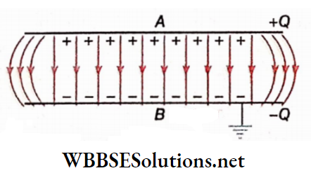
Working principle of capacitor: An insulated metal plate A is connected to an electrical machine, Suppose, the potential of the plate is +V when It Is fully charged, ff C be the capacitance of the plate, the charge on the plate will be,
Q = CV
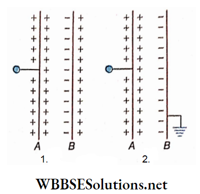
Now if a similar plate B is placed in front of plate A, then due to induction, a negative charge is induced on the inner surface of B and a positive charge on its outer surface.
The induced negative charge, being nearer, lowers the positive potential of plate A. Thus, the capacitance of plate A increases a little (since C = \(\frac{Q}{V}\)). Hence plate A takes a slight additional charge from the electrical machine and raises its potential again to V.
Now if B is earthed, the positive charge on the far side of it moves to the earth and the influence of positive charges is absent, the potential of A falls further. So the capacitance of A increases further and consequently, it will now be able to receive a greater amount of charge from the machine.
So in this way, the capacitance of an insulated charged conductor can be increased with the help of another earthed conductor, placed in its vicinity.
Factors affecting the capacitance of a capacitor:
1. Overlapping nrcu of the plates: The Greater the surface area of the plates, the greater its capacitance. The capacitance decreases with the decrease of the overlapping area.
2. Distance between the two conducting plates: Capacitance increases with the decrease of this distance and vice versa.
3. Nature of the intervening medium between the two ducting plates: Instead of air, if the intervening space of the two plates is filled up with an insulator, e.g., paraffin, glass, paper, etc., the capacitance of a capacitor increases.
Uses of capacitors: Extensive uses of tire capacitors are found in different electrical circuits. In the case of different circuits in AC, the capacitor is almost an indispensable part. Capacitors are used in electronic instruments, radio, television, telephone, the flash circuit of a camera, etc.
Discussions:
1. Charge of a capacitor: Charge of a capacitor means die magnitude of charge on any one of its plates. If one plate possesses a charge + Q, then the other plate will contain a charge -Q. So total charge = +Q + (-Q) = 0. Here, Q is called the charge of a capacitor, it is not the total charge.
2. Ideal capacitor:
If a capacitor is connected to a source of high potential, it is charged to that potential. The capacitor is called an ideal one if it is not discharged automatically even if the source of potential is removed. It preserves its acquired charge without any leakage.
3. Maximum limit of the potential of a capacitor:
A capacitor cannot be charged to any high potential at will. If the value of the potential exceeds a certain maximum limit, the intervening medium loses its insulating properties. Consequently, electric discharge takes place between the capacitor and the intervening medium.
4. Any charged conductor is a capacitor:
Any charged conductor may be considered as a capacitor. The floor or the walls of the room act as the earthed conductor in this case.
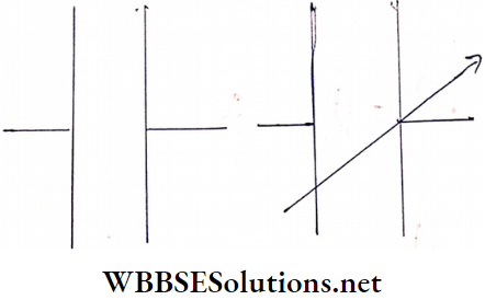
5. Circuit symbol of capacitor:
Two parallel lines of the same size in an electrical circuit diagram, represent a capacitor Symbol of a variable capacitor.
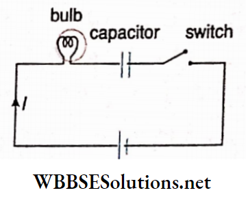
Charging and discharging of a capacitor:
When a battery Is connected to a series resistor and capacitor, charges begin to accumulate on the capacitor.
This Is called the charging of a capacitor. After removal of the battery, the capacitor loses Its accumulated charge through the resistor gradually. Tills Are called discharging of a capacitor.
The two plates A and B of a capacitor are connected to a buttery of electromotive force E through a resistor. Electrons from the negative pole of (lie battery move to plate H.
Simultaneously, a How of electrons starts from plate A to the positive pole of the battery. This produces a charging current.
As negative charges on plate B and positive charges on plate A keep on accumulating, (ho potential difference between die two plates increases.
So the plates act as a cell and consequently, a tendency of electron flow Is established In the direction opposite to that of the initial electron flow. As a result, the die charging current decreases.
Important Formulas in Capacitance
When the potential difference between the two plates A and II becomes equal to the end of the battery, the charging current ceases to flow.
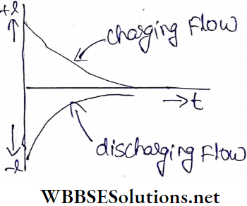
Then it is said that the capacitor has become fully charged. So at the start, the charging current is maximum and afterward, It gradually decreases. When the capacitor is fully charged, the charging current becomes zero.
After removal of the battery from the circuit, l.e„ during discharging electrons from plate 2 flow to plate A and begin to neutralize the positive charge of plate A.
Thus again a current flows in the circuit. This is called discharging and its direction is opposite to that of the charging current- After a while all the electrons of plate B neutralize all the positive charges of plate A.
Then the discharging current becomes zero and the capacitor is said to be completely discharged. So at the start, discharging current is. maximum and It decreases gradually and becomes zero when the capacitor is completely discharged.
In fact, no capacitor is an ideal one. A fully charged capacitor loses its charge in the course of time even if the two plates of it are not connected by a conducting wire.
Finally, the tire capacitor becomes completely discharged. Of course, in this case, the discharging action continues for a long time.
Potential and Capacitance of a Capacitor:
Potential of a capacitor: The potential difference between the two conducting plates of a capacitor is called the potential of a capacitor. Generally, the potential of a capacitor means the potential attained by the insulated plate of the capacitor due to the charge given to it, the grounded plate of the capacitor being at zero potential.
The capacitance of a capacitor:
The capacitance of a capacitor means the capacitance of the insulated conducting plate of the capacitor. So it may be defined as the amount of charge that must be given to the insulated plate to raise its potential by unity. If a charge Q raises its potential by Vi its capacitance, C = \(\frac{Q}{V}\).
Therefore, the capacitance of a capacitor may be defined as the ratio of the magnitude of the charge on any one of the two plates to die difference of potential between them, i.e., the capacitance of a capacitor
= \(\frac{\text { charge on a conducting plate of the capacitor }}{\text { difference of potential between the two plates }}\)
The capacitance of a capacitor is assigned a value of 1 faradic 1 coulomb of charge is required to maintain a potential difference of 1 V between the two conductors or plates of the capacitor.
Here capacitance is always a positive quantity and it does not depend on the nature of charge and potential. The capacitance of a conductor and that of a capacitor are expressed in the same unit.
Usually, a capacitor is rated, bearing the mark of the magnitude of its capacitance and the maximum potential difference that can be applied safely between its two plates.
A capacitor rated 0.04μF 220V means that its capacitance is 0.04μF and the maximum potential difference to be applied between its two plates is 220 V. If it is used in a potential difference higher than 220 V, it may get damaged.
Capacitance And Capacitor Dielectrics
Now we discuss the materials that do not conduct electricity and can be inserted between the plates of a capacitor.
Substances that have no free electrons cannot conduct electricity. They are called insulators or dielectrics. When they are placed in an electric field, charges are induced on their surfaces.
Classification of Dielectrics:
Dielectrics are classified into two groups according to the position of charge within their molecules: O non-polar substance and 0 polar substance.
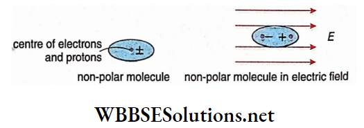
Non-polar substance: A substance in which the center of negative charges (electrons) coincides with that of positive charges (protons) in each of its molecules, is called a non-polar substance.
In the absence of an external electric field, these molecules do not possess any permanent electric dipole moment Thus they are called non-polar molecules.
In the presence of an external electric field, a relative displacement occurs between the centers of positive and negative charge distributions. Thus a non-polar molecule when subjected to an electric field, acquires an electric dipole moment These types of dipoles are called induced dipoles.
Polar substance: A substance in which the center of negative charges (electrons) does not coincide with that of positive charges (protons) in each of its molecules, is called a polar substance.
So, even in the absence of an external electric field, each of these molecules possesses a permanent electric dipole moment So They are called polar molecules.
Example: water (H2O), ammonia (NH3).
Generally, the dipole moments of different molecules of a polar substance are randomly directed. So the resultant dipole moment of a polar substance is zero.
But when subjected to an electric field, each molecule of a polar substance experiences a torque and tends to fall in line with the direction of field lines of the external electric field. As a result, the sample of the polar substance acquires a resultant electric dipole moment.
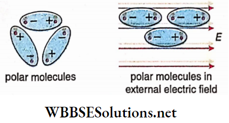
So polar and non-polar molecules behave in a similar manner when subjected to an external electric field.
Polarisation of a Dielectric:
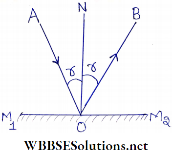
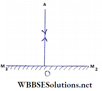
A conductor In an external electric field: If a conductor is placed in an external electric field the free electrons of the conductor orient themselves in a direction opposite to the electric field. This transfer continues until finally, the induced electric field balances the external electric field. In that case, no further displacement of charges takes place i.e., an equilibrium has been reached. So the resultant electric field \(\vec{E}\) inside a conductor is zero.
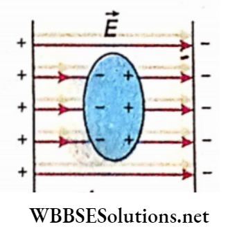
A dielectric in an electric field:
If a dielectric is placed in an external electric field \(\left(\vec{E}_0\right)\), the dipoles align themselves along the lines of force. So an electric field \(\left(\vec{E}_p\right)\) is generated inside the dielectric whose direction is opposite to that of the applied external field \(\left(\vec{E}_0\right) \cdot \vec{E}_P\) is less than \(\left(\vec{E}_0\right)\).
As a dielectric has no free electrons, the external field \(\left(\vec{E}_0\right)\) is not completely balanced by the internal field \(\left(\vec{E}_p\right)\) set up inside the dielectric. So at any point inside a dielectric the resultant intensity \((\vec{E})\) is less than the external field intensity \(\left(\vec{E}_0\right) \cdot \vec{E}_P\) but it does not become zero as in a conductor.
The alignment of the molecules of a dielectric, which behave like electric dipoles under the influence of an external field, is known as electric polarization.
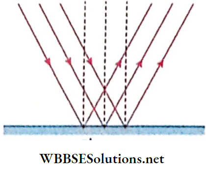
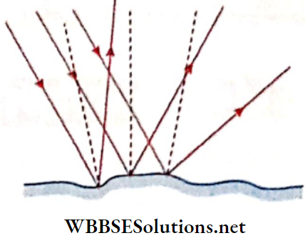
It is observed that one face of the dielectric acquires a net positive charge and the other, a negative. This is because the charges between the two dotted lines neutralize each other’s effect, thus leaving an unbalanced negative charge on the left face and a positive charge on the right face of the dielectric,
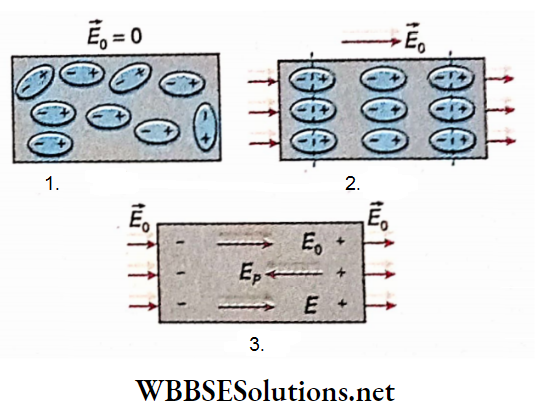
The random arrangement of the molecules of a dielectric has been shown in the absence of any external electric field. Alignment of the molecules along the field lines under the influence of the external field has been shown.
Shows that inside a dielectric, electric field intensity reduces due to electric polarization. The resultant intensity of the electric field inside the dielectric is given by
⇒ \(\vec{E}=\vec{E}_0-\vec{E}_p\)
The electric polarization is directly proportional to die resultant electric field In the dielectric
The capability of storing the charge of a capacitor, i.e., its capacitance can be increased by using a suitable dielectric substance between its two plates.
For Example, air, paraffin, glass, sulfur, mica, paper, etc. are the dielectric substances used as intervention medium in a parallel plate capacitor. The increase in the capacitance of a capacitor depends on a property of dielectric materials, termed as dielectric constant (k).
Definition: The dielectric constant of a material is the ratio of the capacitance of a capacitor filled with the given dielectric material to the capacitance of a similar capacitor without any medium.
So, dielectric constant,
k = \(\frac{capacitance of capacitor with the dielectric as the intervening medium}{capacitance of the same capacitor without anymedium}\)
The dielectric constant is also known as specific inductive capacity (SIC).
The capacitor without any medium between its two plates has only a vacuum between the plates.
By the statement that the dielectric constant of glass is 8.5, we mean that the capacitance of a capacitor will increase 8.5 times if glass is used as a dielectric instead of a vacuum. Naturally, the dielectric constant of a vacuum is 1. The dielectric constant of dry air is 1.000586(≈1).
Capacitance And Capacitor Capacitance Of Some Standard Capacitors
Parallel Plate Capacitor:
It consists of two similar metal plates held parallel to each other, separated by a certain distance. The space in between the two plates contains air or any dielectric, e.g., glass, mica, etc.
Consider two parallel plates A and B separated by a distance d. The area of each plate is a. Plate A is charged with a charge +Q while plate B is grounded. The dielectric constant of the medium between the plates is K.
Now the surface density of charge on plate A will be
⇒ \(\sigma=\frac{Q}{\alpha}\)
The inner face of plate B is charged to -Q due to induction. If the area of the plates is large compared to the die distance between them, the electric lines of force between the plates are straight and parallel except near their ends.
Consequently, the intensity of the electric field between the plates may be taken to be uniform. The slight deviation from this uniformity near the edges may be neglected.
The plates A and B can be considered to be infinite plates with respect to any point in between the two plates. So, the electric field at that point due to the positive charge on plate A is,
⇒ \(E_1=\frac{\sigma}{2 \kappa \epsilon_0} \text {, along } A B\)
The electric field at that internal point will be in the same direction as AB, also due to the negative charge on plate B. Its magnitude is
⇒ \(E_2=\frac{\sigma}{2 \kappa \epsilon_0}\)
Therefore, at all points between the plates A and B, the electric field is
⇒ \(E=E_1+E_2=\frac{\sigma}{2 \kappa \epsilon_0}+\frac{\sigma}{2 \kappa \epsilon_0}=\frac{\sigma}{\kappa \epsilon_0}\)
If V is the potential difference between the plates, then
V = work done to bring a unit positive charge from plate B to plate A
= force acting on the unit charge x distance
= intensity of the electric field x distance
⇒ \(E \cdot d=\frac{\sigma}{\kappa \epsilon_0} \cdot d\)
If C is the capacitance of the capacitor, then
⇒ \(C=\frac{Q}{V}=\frac{\sigma \alpha}{\frac{\sigma}{\kappa \epsilon_0^V} \times d}=\frac{\kappa \epsilon_0 \alpha}{d}\)…(3)
⇒ \(\text { [In CGS units, } C=\frac{K \alpha}{4 \pi d} \text { ] }\)
For air, K = 1
Hence, \(C=\frac{\epsilon_0 \alpha}{d}=\frac{8.854 \times 10^{-12} \times \alpha}{d}\)…(4)
Dependence of the capacitance of a parallel plate capacitor on various factors:
Area of the plates: The capacitance is directly proportional to the area of the plates, i.e., C ∝ a.
1. Distance between the plates: The capacitance of a parallel plate capacitor is inversely proportional to the distance between the plates, i.e., C oc \(\frac{1}{d}\)
2. The nature of the medium between the plates: The capacitance is directly proportional to the permittivity or dielectric constant of the medium between the plates, i.e., C ∝ K.
3. The relation (3) clearly indicates that the capacitance does not depend on the charge Q or the potential V of the capacitor. Only the shape and the intervening medium determine its capacitance.
4. If the common overlapping area between the two plates can be changed by using a hinge arrangement, then changes, and as a result, the capacitance C changes. This technique may be used to design a capacitor, of variable capacitance.
Special case: If n number of parallel plates are alternately connected to form a multi-plate capacitor, the capacitance will be,
⇒ \(C=\frac{(n-1) \kappa \epsilon_0 \alpha}{d}\)
where a = area of each plate,
d = distance between two consecutive plates
The capacitance of a parallel plate capacitor with compound diet dice:
A and B are two parallel plates of which A is charged and B is grounded. Let a be the area of each plate, d the distance between them, and +Q the charge on plate A.
So the surface density of charge on each plate is \(\sigma=\frac{Q}{\alpha}\)
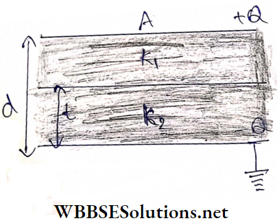
The space between the plates is now filled with two media of permittivites e1 and e2. The thickness of the two layers are (d-1) and t respectively. The intensity of the electric field between the plates may be taken as uniform. If the dielectric constants of the two media are k1 and k2, the intensity of the electric field will be given by,
⇒ \(E_1=\frac{\sigma}{\kappa_1 \epsilon_0}\)
and \(E_2=\frac{\sigma}{\kappa_2 \epsilon_0} ; \epsilon_0\) = permittivity of air or vacuum
∴ The potential difference between the plates Is,
V = E1(d-t) + E2t
⇒ \(\frac{\sigma}{\kappa_1 \epsilon_0}(d-t)+\frac{\sigma}{\kappa_2 \epsilon_0} t=\frac{\sigma}{\epsilon_0}\left[\frac{d-t}{\kappa_1}+\frac{t}{\kappa_2}\right]\)
So, the capacitance of the capacitor,
⇒ \(\frac{Q}{V}\)
⇒ \(\frac{\sigma \alpha}{\frac{\sigma}{\epsilon_0}\left[\frac{d-t}{\kappa_1}+\frac{t}{\kappa_2}\right]}=\frac{\epsilon_0 \alpha}{\left(\frac{d-t}{\kappa_1}+\frac{t}{\kappa_2}\right)}\)
If k1 = 1 (for air) and k2 = k (say),
⇒ \(C=\frac{\epsilon_0 \alpha}{d-t+\frac{t}{\kappa}}=\frac{\epsilon_0 \alpha}{d-\left(t-\frac{t}{\kappa}\right)}\)…(6)
1. Since \(\left(t-\frac{t}{K}\right)\) is a positive quantity, equation (6) shows that the capacitance of a parallel plate capacitor increases with the insertion of any dielectric medium between the plates.
2. If a dielectric of thickness t is inserted in between the two plates of a parallel plate air capacitor, the capacitance of the capacitor becomes equal to that of a capacitor having separation between the plates reduced by \(\left(t-\frac{t}{K}\right)\), i.e., the separation between the two plates effectively decreases by the amount \(\left(t-\frac{t}{K}\right)\).
If we want to get the previous value of the capacitance, the distance between the plates is to be increased. If this increase is x, then
⇒ \(x=t-\frac{t}{K}=t\left(1-\frac{1}{K}\right)\)
3. If n number of dielectric slabs of dielectric constants k1,k2,…,Kn of thicknesses t1, t2…., tn be inserted between the two parallel plates, the capacitance of the capacitor so formed is given by,
⇒ \(C=\frac{\epsilon_0 \alpha}{\frac{t_1}{\kappa_1}+\frac{t_2}{\kappa_2}+\cdots+\frac{t_n}{\kappa_n}}=\frac{\epsilon_0 \alpha}{\sum_1^n \frac{t}{\kappa}}\)
Energy Stored in a Charged Capacitor:
During the charging of an uncharged capacitor, electrons are removed from one plate and transferred to the other gradually. Initially, the charge of the capacitor is zero and so the potential difference between the plates is also zero. As soon as an electron is transferred from one plate to the other, an electric field builds up in the space between the capacitor plates.
This field opposes further transfer. Thus as the charge accumulates on the capacitor plates, increasingly larger amounts of work is to be done to transfer more electrons.
Hence the potential difference increases due to the accumulation of charges. The energy spent for doing that work remains stored as potential energy in the electric field between the two plates of the capacitor.
Calculation: Suppose, at any moment, the charge of a capacitor be q and the potential difference between the two plates is v.
The capacitance of the capacitor, C = \(\frac{q}{v}\)
Further, when some charge of amount dq is given to the capacitor, the work done against the repulsive force due to the existing charge on the capacitor plate,
⇒ \(d W=v d q=\frac{q}{C} d q\)
∴ To give Q the amount of charge, the total work done
⇒ \(W=\int d W\)
= \(\int_0^Q \frac{q}{C} \cdot d q\)
⇒ \(=\frac{1}{2} \cdot \frac{Q^2}{C}\)
= \(\frac{1}{2} C V^2\)
= \(\frac{1}{2} Q V\)
where V = final potential difference between the plates.
This work is stored as potential energy in the capacitor
Energy stored in a charged parallel plate capacitor:
Let us consider a charged parallel plate capacitor.
Here,
a = area of each plate,
d = separation between the plates,
K = dielectric constant of the material between the plates,
σ = surface density of charge on each plate
So, volume between the plates = αd and amount of charge on each plate (Q) = σa.
The capacitance of this parallel plate capacitor,
⇒ \(C=\frac{K \epsilon_0 \alpha}{d}\)
where, ∈0 = permittivity of air or vacuum
Therefore, the energy stored in this charged capacitor,
⇒ \(U=\frac{1}{2} \frac{Q^2}{C}\)
= \(\frac{1}{2}\left(\sigma^2 \alpha^2\right) \frac{d}{\kappa \epsilon_0 \alpha}\)
= \(\frac{\sigma^2 \alpha d}{2 \kappa \epsilon_0}\)
The unit of U is joule (J). This energy is stored in the electric field between the plates of the capacitor.
[In the CGS system, the expression for U is obtained by replacing
⇒ \(\epsilon_0 \text { by } \frac{1}{4 \pi} . \text { So, } U=\frac{2 \pi \sigma^2 a d}{\kappa}\); its unit is erg.]
Energy stored per unit volume or energy density between the plates:
Energy stored per unit volume,
⇒ \(u=\frac{U}{\alpha d}=\frac{\sigma^2}{2 \kappa \epsilon_0}\)
This is called the energy density in the electric field of the
capacitor.
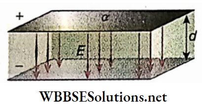
Now, the electric field is uniform, except at the ends, inside a parallel plate capacitor, provided the plate area is very large compared to the separation between the plates.
From Gauss’ theorem, we already know that the uniform electric field between the two plates of a parallel plate capacitor, neglecting end effects, is
⇒ \(E=\frac{\sigma}{\kappa \epsilon_0} ; \text { then } \sigma=\kappa \epsilon_0 E\)
So, the energy density between the two plates is,
⇒ \(u=\frac{\left(\kappa \epsilon_0 E\right)^2}{2 \kappa \epsilon_0}=\frac{1}{2} \kappa \epsilon_0 E^2\)…(1)
For vacuum or air, K = 1 . Then equation (1) becomes,
⇒ \(u=\frac{1}{2} \epsilon_0 E^2\)…(2)
[In the CGS system, the equation (1) and (2) become, due to the replacement of
\(\epsilon_0 \text { by } \frac{1}{4 \pi}, u=\frac{1}{8 \pi} \kappa E^2 \text { and } u=\frac{1}{8 \pi} E^2\)]
In SI, the unit of u is J.m-3 [In the CGS system, it is erg.cm-3 ]
Dimension of \(u=\frac{\text { dimension of energy }}{\text { dimension of volume }}\)
⇒ \(\frac{M L^2 T^{-2}}{L^3}\)
= \(M L^{-1} T^{-2}\)
The expressions (1) and (2) of energy density in an electric field have been derived by considering the special case of a parallel plate capacitor. However, it can be proved that these two expressions are quite general expressions – true not only for parallel plate capacitors but also for electric fields of any other type.
These expressions give the energy density, i.e. energy in a unit volume around any, point in an electric field of any type. The rigorous proofs of the expressions are beyond the scope of our present discussions.
Energy density around a point In an electric field.’ Suppose, a point charge q is placed at a point 0. Another point P in air, is at a distance r from 0. Then the electric field at P,
⇒ \(E=\frac{1}{4 \pi \epsilon_0} \frac{q}{r^2}\)
So, the energy density of the tire electric field around point P is,
⇒ \(u=\frac{1}{2} \epsilon_0 E^2=\frac{1}{2} \epsilon_0 \frac{q^2}{16 \pi^2 \epsilon_0^2 r^4}=\frac{q^2}{32 \pi^2 \epsilon_0 r^4}\)
Then, in a small volume v around the point P, the energy stored is,
⇒ \(U=u v=\frac{q^2 v}{32 \pi^2 \epsilon_0 r^4}\)

Capacitance And Capacitor Capacitance Of Some Standard Capacitors Numerical Examples
Example 1. The area of each plate of a parallel plate glass capacitor is 314 cm2. Its plates are separated distance 1cm. What will be the radius of a sphere having a capacitance equal to that of this capacitor? [k of glass = 8 ].
Solution:
The capacitance of the sphere
⇒ \(C=\frac{\kappa \alpha}{4 \pi d}=\frac{8 \times 314}{4 \times \pi \times 1} \approx 200 \mathrm{statF}\)
So, the radius of the sphere = 200 cm.
Example 2. The area of each plate of a parallel plate capacitor is 22 cm² and the plates are kept separated by a paraffin paper of thickness 1 mm. The specific inductive capacity (SIC) of paraffin paper is 2. What are the capacitance of the capacitor and the surface density of charge under a potential difference of 330 V?
Solution:
The capacitance of the capacitor
⇒ \(C=\frac{\kappa \alpha}{4 \pi d} \quad\left[\text { Here, } \kappa=2 ; \alpha=22 \mathrm{~cm}^2 ; d=0.1 \mathrm{~cm}\right]\)
⇒ \(\frac{2 \times 22}{4 \pi \times 0.1}=35 \mathrm{statF}\)
∴ \(Q=C V=35 \times \frac{330}{300} {statC}\left[∵ V=330 \mathrm{~V}=\frac{330}{300} \text { statV }\right]\)
∴ Surface density of charge,
⇒ \(\sigma=\frac{Q}{\alpha}=\frac{35 \times 330}{300 \times 22}\)
= 1.75 statC.cm-2
Example 3. The distance between the two plates of a parallel plate air capacitor is d. A piece of metal of thickness \(\frac{d}{2}\) and of area equal to that of the plates is inserted between the plates. Compare the capacitances in the two cases.
Solution:
In the first case, the capacitance of the parallel plate capacitor,
⇒ \(C_1=\frac{\epsilon_0 \alpha}{d}\)
We know that the intensity of the electric field inside a metal is zero. So, if a piece of metal of thickness \(\frac{d}{2}\) is inserted between the plates now becomes \(\left(d-\frac{d}{2}\right)=\frac{d}{2}\). Therefore, the capacitance of the capacitor becomes
⇒ \(C_2=\frac{\epsilon_0 \alpha}{d / 2}=\frac{2 \epsilon_0 \alpha}{d}\)
∴ \(\frac{C_1}{C_2}=\frac{\left(\epsilon_0 \alpha\right) / d}{\left(2 \epsilon_0 \alpha\right) / d}\)
= \(\frac{1}{2}\)
Example 4. The conducting plates of a parallel plate capacitor are separated by 2 cm from each other. A dielectric slab (K = 5) of thickness 1 cm is inserted between the two plates. The distance between the plates is now so changed that the capacitance of the capacitor remains the same. What will be the new distance between the plates?
Solution:
Let the present distance between the plates be d. According to the question,
⇒ \(\frac{\epsilon_0 \alpha}{2}=\frac{\epsilon_0 \alpha}{\left[d-t+\frac{t}{\kappa}\right]}\) [t = thickness of the dielectric slab = 1 cm; K = 5 ]
or, \(\frac{1}{2}=\frac{1}{\left[d-1+\frac{1}{5}\right]}\)
or, \(2=\left[d-1+\frac{1}{5}\right]=d-\frac{4}{5}\)
or, d = \(\frac{14}{5}\)
= 2.8 cm
Example 5. The surface area of each plate of a parallel plate capacitor is 50 cm2. They are separated by 2mm in air. It is connected with a 100V power supply. Now a dielectric (K = 5) is inserted between its two plates. What will happen
- If the voltage source remains connected and
- If the voltage sources are absent during this insertion?
Solution:
We know, that the capacitance of a parallel plate capacitor is
⇒ \(C=\frac{k \epsilon_0 \alpha}{d}\)
For air, the capacitance,
⇒ \(C_1=\frac{\epsilon_0 \alpha}{d}\) [∈0 = 8.854 x 10⁻¹² F.m-1, a = 50cm2 = 5 X 10⁻²m2, d = 2 mm = 2 X 10⁻³ m]
⇒ \(\frac{8.854 \times 10^{-12} \times 5 \times 10^{-3}}{2 \times 10^{-3}}\)
= 2.21 x 10⁻¹¹ F
For the dielectric (k = 5), the capacitance,
⇒ \(C_2=\frac{\kappa \epsilon_0 \alpha}{d}\)
= 5 x 2.21 x 10-11
= 1.11 x 10⁻¹⁰ F
1. If a dielectric is inserted, the capacitance of a parallel plate capacitor increases. Since the capacitor is still connected to the power supply, its potential will remain constant.
When the intervening medium is air, charge on the capacitor,
Q0 = capacitance x potential
= 2.21 X 10-11 X 100
= 2.21 X 10⁻⁹ C
When the intervening medium is the dielectric (k = 5), charge on the capacitor,
Q = 1.11 x 10-10 x 100
= 1.11 x 10⁻⁸C
∴ Change in charge of the capacitor
= Q – Q0
= 1.11 x 10⁻⁸ – 2.21 x 10-9
= 8.89 x 10⁻⁹ C
Change in potential difference = 0.
2. If the battery is removed, the charge stored remains the same.
So change in charge of the capacitor = 0.
According to the question, the potential difference between the plates of the capacitor before the insertion of the dielectric = 100 V.
After the insertion of the dielectric, the potential difference between the plates is,
⇒ \(V=\frac{Q_0}{C_2}=\frac{2.21 \times 10^{-9}}{1.11 \times 10^{-10}}\)
= 19.91 V
So, the potential difference decreases.
Change in potential difference
= 100 – 19.91
= 80.09 V
Example 6. Each of the two square plates of a capacitor has sides of length l. The angle d between the two plates is very small, If the medium between the plates is air and the minimum distance between them is t, determine the capacitance of the capacitor
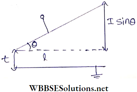
Solution:
The average distance between the plates,
⇒ \(d=\frac{t+(t+l \sin \theta)}{2}=t+\frac{l}{2} \theta\) [∵ θ is very small, sinθ ≈ 0]
∴ The capacitance of the capacitor,
⇒ \(C=\frac{\epsilon_0 \alpha}{d}=\frac{\epsilon_0 l^2}{t+\frac{l}{2} \theta}=\frac{\epsilon_0 l^2}{t\left(1+\frac{l \theta}{2 t}\right)}=\frac{\epsilon_0 l^2}{t}\left(1+\frac{l \theta}{2 t}\right)^{-1}\)
⇒ \(\approx \frac{\epsilon_0 l^2}{t}\left(1-\frac{l \theta}{2 t}\right)\)
Example 7. A parallel plate air capacitor has a capacitance of 2pF. Now, the separation between the plates is doubled, and the space is filled with wax. If the capacitance rises to 6 pF, what is the dielectric constant of wax?
Solution:
Initial separation between the plates = d; area of each plate = α.
∴ Capacitance in the 1st case,
⇒ \(C_1=\frac{\epsilon_0 \alpha}{d}\)
The final separation between the plates = 2d; dielectric constant of wax = k.
∴ Capacitance in the 2nd case,
⇒ \(C_2=\frac{\kappa \epsilon_0 \alpha}{2 d}\)
∴ \(\frac{C_1}{C_2}=\frac{2}{\kappa} \text { or, } \kappa=2 \times \frac{C_2}{C_1}=2 \times \frac{6 \mathrm{pF}}{2 \mathrm{pF}}=6\)
Example 8. The area of each plate of a parallel plate capacitor is A – 600 cm² and their separation is d = 2.0 mm. The capacitor is connected to a 200 V DC source. Find out
- The uniform electric field between the plates In the SI unit and
- The surface density, of charge on any plate. Given, ∈0 = 8.85 x 10⁻¹²F m-1
Solution:
Here, A = 600 cm2
= 600 x 10-4m2
= 6 x 10⁻²m2;
d = 2.0 mm
= 2 x 10⁻³ m.
1. The uniform electric field between the plates,
⇒ \(E=\frac{V}{d}=\frac{200}{2 \times 10^{-3}}=10^5 \mathrm{~V} \cdot \mathrm{m}^{-1}\)
2. If cr = surface density of charge on any plate, then
⇒ \(E=\frac{\sigma}{\epsilon_0}\)
∴ \(\sigma=\epsilon_0 E=\left(8.85 \times 10^{-12}\right) \times 10^5\)
= 8.85 x 10⁻⁷ C m-2
Example 9. The potential of a capacitor increases from zero to 150 V when a charge of 10 esu Is imparted to it. What will be the energy stored in the capacitor?
Solution:
Energy stored within the capacitor
⇒ \(\frac{1}{2} Q V=\frac{1}{2} \times 10 \times \frac{150}{300}\)
= 2.5 erg.
Example 10. Find out the energy content in a volume of 1 cm³ around a point, situated in the electric field of a point charge of 10 C, at a distance of 2 m in air from the position of the point charge. Given,∈0 = 8.85 x 10⁻¹² F.m-1
Solution:
The electric field at the referred point due to the point charge,
⇒ \(E=\frac{1}{4 \pi \epsilon_0} \frac{q}{r^2}[\text { Here, } q=10 \mathrm{C}, r=2 \mathrm{~m}]\)
∴ Energy density at the point
⇒ \(u=\frac{1}{2} \epsilon_0 E^2=\frac{1}{2} \epsilon_0 \cdot \frac{1}{16 \pi^2 \epsilon_0^2} \frac{q^2}{r^4}=\frac{q^2}{32 \pi^2 \epsilon_0 r^4}\)
∴ The energy content in a volume of 1 cm3, i.e., 10-6 m3,
U = u x 10-6
⇒ \(\frac{q^2}{32 \pi^2 \epsilon_0 r^4} \times 10^{-6}\)
⇒ \(\frac{10^2 \times 10^{-6}}{32 \times(3.14)^2 \times\left(8.85 \times 10^{-12}\right) \times 2^4} \approx 2240 \mathrm{~J}\)
Example 11. Estimate the percentage change of the energy stored in a parallel plate capacitor, if the separation between its plates is reduced by 10%, keeping the voltage of the charging source unchanged.
Solution:
Let d = initial separation between the plates.
∴ Final separation,
d’ = d – (10% of d)
= d – \(\frac{d}{10}\)
= 0.9d
The initial and final values of the energy stored in the capacitor are,
⇒ \(U=\frac{1}{2} C V^2=\frac{1}{2} \frac{\epsilon_0 \alpha}{d} V^2 \text { and } U^{\prime}=\frac{1}{2} \cdot \frac{\epsilon_0 \alpha}{0.9 d} V^2\)
∴ Percentage increase in energy
⇒ \(\frac{U^{\prime}-U}{U} \times 100=\left(\frac{U^{\prime}}{U}-1\right) \times 100=\left(\frac{1}{0.9}-1\right) \times 100\)
⇒ \(\frac{0.1}{0.9} \times 100=\frac{100}{9}\)
= 11.1 %
Example 12. A 900 pF capacitor is charged to 100 V by a battery. How much energy is stored in the capacitor?
Solution:
Here, C = 900 pF
= 900 x 10-12F
=9 x 10⁻¹⁰F;
Energy stored within the capacitor,
E = \(\frac{1}{2}\)CV2
= \(\frac{1}{2}\) x (9 X 1010) X (100)2
= 4.5 x 10⁻⁶J
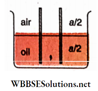
Example 13. The capacitance of a parallel plate air capacitor is C. The capacitor is immersed halfway into an oil of dielectric constant 1.6 with the plates perpendicular to the surface of the oil. What will be the capacitance of this capacitor?
Solution:
The capacitance of the half of the capacitor immersed in oil,
⇒ \(C_1=\frac{\kappa \epsilon_0}{d} \cdot \frac{\alpha}{2}=\frac{1.6 \epsilon_0}{d} \cdot \frac{\alpha}{2}\)
The capacitance of the other half of the capacitor in air,
⇒ \(C_2=\frac{\epsilon_0}{d} \cdot \frac{\alpha}{2}\)
Net capacitance = \(C_1+C_2=\frac{1.6 \epsilon_0}{d} \cdot \frac{\alpha}{2}+\frac{\epsilon_0}{d} \cdot \frac{\alpha}{2}=\frac{2.6 \epsilon_0}{d} \cdot \frac{\alpha}{2}\)
⇒ \(\frac{1.3 \epsilon_0}{d} \cdot \alpha=1.3 C\left[∵C=\frac{\epsilon_0 \alpha^2}{d}\right]\)
Capacitance And Capacitor Notes For Class 12 WBCHSE
Capacitance And Capacitor Combination Of Capacitors
Series combination: in this type of combination of capacitors, the first plate of the first capacitor is joined to the electric source, its second plate is joined to the first plate of the second capacitor, the second plate of the second capacitor is joined to tire first plate of tire third capacitor and so on. The second plate of the last capacitor is grounded, the rest of the system being kept insulated.
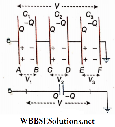
Calculation of equivalent capacitance: Let three capacitors of capacitances C1, C2, and C3 be connected in series. Now a charge +Q be given from a source to the first plate A of the first capacitor, this will induce a charge -Q on the other plate B of this capacitor and a charge +Q on the first plate C of the second capacitor, and so on. All the capacitors will have the same charge Q. The final free positive charge from the last plate of the system moves to the earth.
If V1, V2, and V3 are the potential differences across the capacitors C3, C2, and C3 and V is the potential difference between the first plate A and the last plate F of the combination, then
V= V1+ V2 + V3 …(1)
For the first capacitor, \(V_1=\frac{Q}{C_1}\)
For the second capacitor, \(V_2=\frac{Q}{C_2}\)
For the third capacitor, \(V_3=\frac{Q}{C_3}\)
∴ From equation (1) we have,
⇒ \(V=\frac{Q}{C_1}+\frac{Q}{C_2}+\frac{Q}{C_3}\)
or, \(V=Q\left(\frac{1}{C_1}+\frac{1}{C_2}+\frac{1}{C_3}\right)\)…..(2)
Now suppose that instead of this combination, a single capacitor is used such that the same charge (Q) given to this new capacitor produces the same potential difference ( V) between its two plates. This single capacitor is known as the equivalent capacitor of the combination and its capacitance is known as the equivalent capacitance
If C is the equivalent capacitance of the series combination of the capacitors C1, C2, and C3, then
V = \(\frac{Q}{C}\)…(3)
From equations (2) and (3) we get,
⇒ \(\frac{Q}{C}=Q\left(\frac{1}{C_1}+\frac{1}{C_2}+\frac{1}{C_3}\right)\)
or, \(\frac{1}{C}=\frac{1}{C_1}+\frac{1}{C_2}+\frac{1}{C_3}\)…(4)
For n number of capacitors connected in series, the equivalent capacitance C is given by,
⇒ \(\frac{1}{C}=\frac{1}{C_1}+\frac{1}{C_2}+\cdots+\frac{1}{C_n}\)…(5)
Thus if several capacitors are connected in series, the reciprocal of the capacitance of the equivalent capacitor is equal to the sum of the reciprocals of the capacitances of the individual capacitors.
Now, \(\frac{1}{C}=\frac{1}{C_1}+\frac{1}{C_2}+\frac{1}{C_3}+\cdots+\frac{1}{C_n}\)
∴ \(\frac{1}{C}>\frac{1}{C_1}, \frac{1}{C_2}, \frac{1}{C_3}, \cdots, \frac{1}{C_n}\)
or, \(C<C_1, C_2, C_3, \cdots, C_n\)
Clearly, for series combinations, the equivalent capacitance is always less than any individual capacitance in the series.
Parallel combination:
In this type, of combination the first plates, i.e., the insulated plates of all the capacitors are connected to a common point A, and the second plates, i.e., the grounded plates to another common point B. Point A is connected to an electric source and point B is earthed
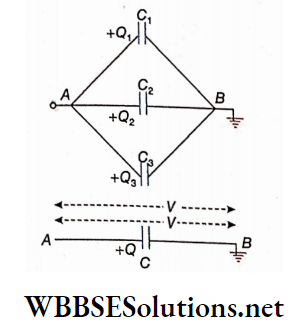
Calculation of equivalent capacitance: Three capacitors of capacitances C1, C2, and C3 connected in parallel. The insulated plates of the three capacitors are connected to an electric source having potential V and other plates are earthed. So the potential difference between the two plates of each capacitor is V. A charge +Q drawn from the supply divides into Q1, Q2, and Q3 according to the capacity of the different capacitors. So,
Q = Q1 + Q2+ Q3….(6)
For the first capacitor,
Q1 = C1V
For the second capacitor,
Q2 = C2V
For the third capacitor,
Q3 = C3V
∴ From the equation (6) we get,
Q = C1V + C2V + C3V
or, Q = V(C1 + C2 + C3)….(7)
If the capacitors connected in parallel are replaced by a single capacitor so that the same potential difference V is produced if charge +Q is given to its insulated plate, the single capacitor is known as the equivalent capacitor of the combination and its capacitance is known as the equivalent capacitance. If C is the equivalent capacitance of the parallel combination of the capacitors C1, C2, and C3, then
Q = CV…..(8)
From equations (7) anil1(8) we have
CV = V(C1 + C2 + C3)
or, C = C1 + C2 + C3….(9)
For n number of capacitors connected in parallel, the equivalent capacitance C is
C = C1 + C2 + …. + Cn ,
Thus the equivalent capacitance of the capacitors joined in parallel is equal to the sum of their individual capacitances.
Clearly, the equivalent capacitance of a number of capacitors in parallel is greater than any individual capacitance in the combination.
Capacitors are connected in parallel when a large capacitance for a small potential is required.
Capacitance And Capacitor Notes For Class 12 WBCHSE
Unit 1 Electrostatics Chapter 4 Capacitance And Capacitor Combination Of Capacitors Numerical Examples
Example 1. H A condenser Is composed of 21 circular plates placed one after the other. The diameter of each plate is 10 cm. The consecutive plates are separated by 0.2 mm thick mica sheets of dielectric constant 6. If the alternate circular plates are connected, calculate the capacitance of the condenser μF.
Solution:
The condenser is composed of 21 circular plates and alternate plates are connected. So here we get 20 identical capacitors connected in parallel whose capacitance is
⇒ \(C=\frac{20 \kappa \epsilon_0 \alpha}{d}\)
⇒ \(\frac{20 \times 6 \times 8.854 \times 10^{-12} \times \pi \times 2.5 \times 10^{-3}}{2 \times 10^{-4}}\)
= 4.17 x 10⁻⁸
F = 0.0417μF
[Here, k = 6, a = n x (5)2 cm2 = n x 2.5 x 10⁻³ m2, d = 2 x 10⁻⁴m, ∈0 = 8.854 x 10⁻¹² C2.N-1.m2 ]
Example 2. A condenser is composed of 200 circular tin plates placed one after the other. The consecutive plates are separated by 0.5 mm thick mica sheets of dielectric constant 6. If the alternate tin plates are connected and the capacitance of the entire condenser is 0.4μF, what is the radius of each tin plate?
Solution:
The condenser is composed of 200 circular plates and alternate plates are connected. So, here we get 199 identical capacitors connected in parallel. Now capacitance of each capacitor is,
⇒ \(C=\frac{\kappa \alpha}{4 \pi d}=\frac{\kappa \pi r^2}{4 \pi d}=\frac{\kappa r^2}{4 d}\)
∴ \(\frac{\kappa r^2}{4 d} \times 199=0.4 \times 10^{-6} \times 9 \times 10^{11}\) [∵ 0.4μF =0.4 x 10⁻⁶F and IF = 9 x 10¹¹ statF]
or, \(\frac{6 r^2}{4 \times 0.05} \times 199=3.6 \times 10^5\)
or, \(r^2=\frac{3.6 \times 10^5 \times 4 \times 0.05}{6 \times 199}\)
or, r-2 = 60.3
or, r = 7.76
So, the radius of each tin plate = 7.76 cm.
Example 3. The equivalent capacitances of the parallel and the series combinations of two capacitors are 5μF and 1.2μF, respectively. Calculate the capacitances of each capacitor
Solution:
Let the capacitances of the two capacitors be C1μF and C2μF. According to the question,
C1 + C2 = 5…(1)
and \(\frac{C_1 C_2}{C_1+C_2}=1.2\)
or, C1C2 = 1.2 x 5
= 6 ….(2)
or, C1(5-C1)-6 = 0 [with the help of equation (1)]
or, \(C_1^2-5 C_1+6=0\)
or, (C1-3)(C1-2) = 0
∴ C1 = 3 or, 2
If C1 = 3;
C2 = 5-3
= 2
and if C1 = 2;
C2 = 5-2
= 3
So, the capacitances of the two capacitors are 3μF and 2μF.
Example 4. Two capacitors of capacitances 20μF and 60μF are connected in series. If the potential difference between the two ends of the combination is 40 V, calculate the terminal potential differences of each capacitor
Solution:
If C is the equivalent capacitance of the combination,
then
⇒ \(C=\frac{20 \times 60}{20+60}=15 \mu \mathrm{F}=15 \times 10^{-6} \mathrm{~F}\)
∴ The total charge of the combination,
Q = CV
= 15 x 10-6 x 40
= 6 x 10⁻⁴C
Since the two capacitors are connected in series, the charge on each capacitor is equal to the total charge of the combination, i.e., 6 x 10⁻⁴C.
∴ The potential difference between the two plates of the capacitor having capacitance C1 is,
⇒ \(V_1=\frac{Q}{C_1}=\frac{6 \times 10^{-4}}{20 \times 10^{-6}}\)
= 30 V
Again, the potential difference between the two plates of the capacitor having capacitance C2 is,
⇒ \(V_2=\frac{Q}{C_2}=\frac{6 \times 10^{-4}}{60 \times 10^{-6}}\)
= 10V
Example 5. A charged condenser is made to share its charge with an uncharged condenser of twice its capacitance. Find the sum of the energy of the two condensers.
Solution:
Let the capacitance of the charged condenser be C and let its charge be Q.
Before sharing of charge, the energy of the charged condenser is,
⇒ \(E_1=\frac{Q^2}{2 C}\)
The capacitance of the other condenser = 2C; since the charged condenser is made to share its charge with the second condenser, it is clear that the condensers are connected in parallel with each other.
∴ Equivalent capacitance of them
= C + 2C
= 3C
∴ Energy of the combination = \(=\frac{1}{2} \cdot \frac{Q^2}{3 C}=\frac{1}{3} \cdot \frac{1}{2} \frac{Q^2}{C}=\frac{1}{3} E_1\)
WBCHSE Class 12 Physics Chapter 4 Solutions
Example 6. A spherical drop of water carries a charge of 10 X 10-12 C and has a potential of 100 V at its surface.
- What is the radius of the drop?
- If eight such charged drops combine to form a single drop, what will be the potential at the surface of the new drop?
Solution:
1. Charge of a spherical water drop,
Q = 10 x 10-12C
= 10 x 10-12 x 3 x 109 esu of charge
= 3 x 10⁻² esu of charge
Potential of the drop, \(V=\frac{100}{300}=\frac{1}{3} \text { stat } \mathrm{V}\)
The capacitance of the drop,
⇒ \(C=\frac{Q}{V}=\frac{3 \times 10^{-2}}{\frac{1}{3}}\)
= 0.09 statF
In CGS units, the radius of a spherical conductor = its capacitance.
The radius of the drop, r = 0.09 cm.
2. If R is the i&dius of the large drop, then
⇒ \(\frac{4}{3} \pi R^3=8 \times \frac{4}{3} \pi r^3\)
or, R = 2r
= 2x 0.09
= 0.18 cm
Total charge, Q = 8 x 3 x 10-2
= 24 x 10-2 statC
∴ Potential at the surface of the new drop,
⇒ \(V=\frac{Q}{C}=\frac{Q}{R}=\frac{24 \times 10^{-2}}{0.18}=\frac{4}{3}\)
= 1.33 statV
= 1.33 X 300 V
= 400 V
Example 7. Three plates of the same size form a system of capacitors. Each plate has an area a. The intermediate differences between the plates are d1 and d2, respectively. The space between the first two plates is occupied by a dielectric of constant and that between the second and third plates by a dielectric of constant K2. Calculate the capacitance of the system.
Solution:
The three plates form two capacitors connected in series.
The capacitance of the first capacitor,
⇒ \(C_1=\frac{\kappa_1 \epsilon_0 \alpha}{d_1}\)
The capacitance of the second capacitor
⇒ \(C_2=\frac{\kappa_2 \epsilon_0 \alpha}{d_2}\)
If C is the equivalent capacitance of the whole system, then
⇒ \(\frac{1}{C}=\frac{1}{C_1}+\frac{1}{C_2}=\frac{d_1}{\kappa_1 \epsilon_0 \alpha}+\frac{d_2}{\kappa_2 \epsilon_0 \alpha}=\frac{1}{\epsilon_0 \alpha}\left(\frac{d_1}{\kappa_1}+\frac{d_2}{\kappa_2}\right)\)
∴ \(C=\epsilon_0 \alpha \cdot \frac{1}{\frac{d_1}{\kappa_1}+\frac{d_2}{\kappa_2}}\)
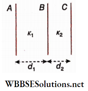
Example 8. The capacitance of a parallel plate air capacitor is 9 pF. The separation between the plates is d. The intermediate space is filled up by two dielectric media. The widths of them are,\(\frac{d}{3} \text { and } \frac{2 d}{3}\), and their dielectric constants are 3 and 6, respectively. Find the capacitance of the parallel plate capacitor.
Solution:
As the capacitors are connected in series the equivalent capacitance,
⇒ \(C_{\mathrm{eq}}=\frac{C_1 C_2}{C_1+C_2}\)
We know that,
⇒ \(C_1=\kappa_1 \frac{\epsilon_0 A}{\frac{d}{3}} \text { and } C_2=\kappa_2 \frac{\epsilon_0 A}{\frac{2 d}{3}}\) [where A = area of each plate]
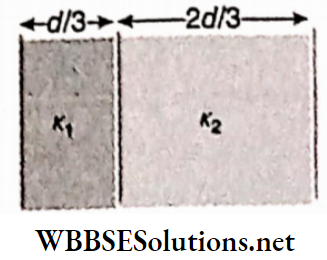
Putting the values of C1 and C2 in equation (1),
⇒ \(C_{\mathrm{eq}}=\frac{\frac{\epsilon_0 A}{\frac{d}{3}} \times \frac{\epsilon_0 A}{\frac{2 d}{3}} \times \kappa_1 \kappa_2}{\frac{\epsilon_0 A}{\frac{d}{3}}\left(\kappa_1+\frac{\kappa_2}{2}\right)}\)
∵ \(\frac{\epsilon_0 A}{d}=9 \mathrm{pF} \text { and } \kappa_1=3, \kappa_2=6\)
So, \(C_{\text {eq }}=\frac{3 \times 9 \times 3 \times \frac{9}{2} \times 3 \times 6}{3 \times 9\left(3+\frac{6}{2}\right)}\)
= 40.5 pF
Example 9. Three capacitors having capacitances 1μF, 2μF, and 3μF are Joined in series. A potential difference of 1100 V is applied to the combination. Find the charge and potential difference across each capacitor.
Solution:
If C is the equivalent capacitance of the combination, then,
⇒ \(\frac{1}{C}=\frac{1}{1}+\frac{1}{2}+\frac{1}{3}=\frac{11}{6} \text { or, } C=\frac{6}{11} \mu \mathrm{F}=\frac{6}{11} \times 10^{-6} \mathrm{~F}\)
∴ The total charge of the combination,
Q = CV
= \(\frac{6}{11}\) x 10-6 x 1100
= 6 x 10⁻⁴ c
Since the capacitors are connected in series, the charge on each capacitor is equal to the total charge, i.e., 6 x 10⁻⁴ C. Potential difference across the plates of the first capacitor,
⇒ \(V_1=\frac{Q}{C_1}=\frac{6 \times 10^{-4}}{1 \times 10^{-6}}=600 \mathrm{~V}\)
Similarly, for the other two capacitors, respectively,
⇒ \(V_2=\frac{Q}{C_2}=\frac{6 \times 10^{-4}}{2 \times 10^{-6}}=300 \mathrm{~V}\)
and, \(V_3=\frac{Q}{C_3}=\frac{6 \times 10^{-4}}{3 \times 10^{-6}}=200 \mathrm{~V}\)
WBCHSE Class 12 Physics Chapter 4 Solutions
Example 10. Two capacitors having capacitances 0.1μV and 0.01μF are joined in series. A potential difference of 22 V is applied to the combination. If the capacitors are now joined in parallel, what will be the change in stored energy?
Solution:
If the capacitors are joined in series, their equivalent capacitance,
⇒ \(C_s=\frac{C_1 \times C_2}{C_1+C_2}=\frac{0.1 \times 0.01}{0.1+0.01}=\frac{1}{110} \mu \mathrm{F}=\frac{10^{-6}}{110} \mathrm{~F}\)
∴ Energy stored in the combination,
⇒ \(E_1=\frac{1}{2} C_s V^2=\frac{1}{2} \times \frac{10^{-6}}{110} \times(22)^2 \mathrm{~J}\)
= 22 erg
If the capacitors are joined in parallel, their equivalent capacitance,
Cp = C1 + C2
= 0.1 + 0.01
= 0.11μF
= 0,11 x 10⁻⁶F
∴ Energy stored in this combination,
⇒ \(E_2=\frac{1}{2} C_p V^2=\frac{1}{2} \times 0.11 \times 10^{-6} \times(22)^2 \mathrm{~J}\)
= 266.2 erg
The change in stored energy = E2-E1
= 266.2- 22
= 244.2 erg
∴ Stored energy increases by 244.2 erg.
Example 11. Five capacitors have been arranged in a circuit. The capacitance of each capacitor is C. Determine the effective capacitance between points A and B.
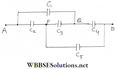
Solution:
The equivalent circuit is like that,
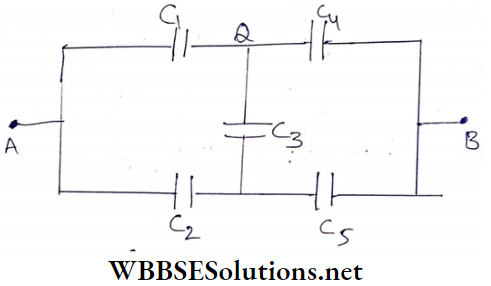
From symmetries see that P and Q are equipotential points. So no current will pass through C3.
So, the effective capacitance between A and B \(=\frac{C}{2}+\frac{C}{2}=C\)
Example 12. Show that the equivalent capacitance of an infinite circuit formed by the repetition of a similar loop made of two similar capacitors, each of capacitance C = (√5 + l) μF, is 2μF.
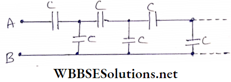
Solution:
Let the capacitance of the infinite circuit be C’.
So the circuit on the right-hand side starting from the second loop is also infinite. Therefore, its capacitance will also be C’.
In this case, the equivalent circuit will be that
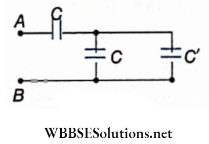
∴ \(\frac{1}{C^{\prime}}=\frac{1}{C}+\frac{1}{C^{\prime}+C}\)
or, \(\frac{1}{C^{\prime}}-\frac{1}{C^{\prime}+C}=\frac{1}{C}\)
or, \(\frac{C^{\prime}+C-C^{\prime}}{C^{\prime}\left(C^{\prime}+C\right)}=\frac{1}{C}\)
or, \(C^{\prime 2}+C^{\prime} C-C^2=0\)
or, \(C^{\prime}=\frac{-C \pm \sqrt{C^2+4 C^2}}{2}=\frac{(-1 \pm \sqrt{5}) C}{2}\)
Neglecting the negative value of C’ we have
⇒ \(C^{\prime}=\frac{(\sqrt{5}-1) C}{2}=\frac{(\sqrt{5}-1)}{2} \cdot(\sqrt{5}+1)\)
= 2μF
Example 13. Twelve capacitors, each of capacitance 10μF, are inserted at the sides of a cube made of conducting wires. Determine the equivalent capacitance between A and B.
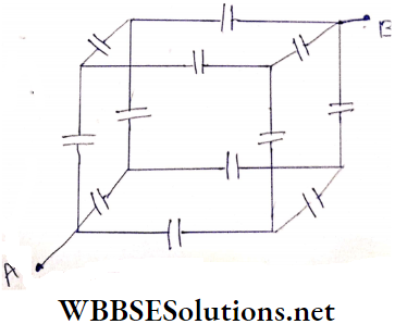
Solution:
Let a charge Q be given to the circuit from a source. The distribution of charge in the different capacitors has been shown
Let C’ be the equivalent capacitance between the points A and B.
Capacitance of each capacitor = C = 10μF
∴ \(V_{\text {A}}-V_B=\frac{Q}{C^{\prime}}\)….(1)
Again considering the path AMNB we have,
⇒ \(V_A-V_B=\frac{Q}{\frac{3}{C}}+\frac{Q}{C}+\frac{Q}{C}=\frac{Q}{3 C}+\frac{Q}{6 C}+\frac{Q}{3 C}=\frac{5}{6} \cdot \frac{Q}{C}\)…(2)
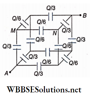
∴ From equations (1) and (2) we have,
⇒ \(\frac{Q}{C^{\prime}}=\frac{5}{6} \cdot \frac{Q}{C}\)
or, \(C^{\prime}=\frac{6 C}{5}=\frac{6}{5} \times 10\)
= 12μF
Example 14. Two identical parallel plate air capacitors are connected to a battery. At first, the key S is closed and then It is opened. The spaces between the two capacitors are now filled up with a dielectric trie, having dielectric constant 3. Determine the ratio of the energy stored in the two capacitors before and after insertion of the dielectric.
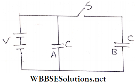
Solution:
When the key was closed, the potential of each capacitor was equal.
Let this value ofpotential be V.
Energy of the capacitor A = \(\frac{1}{2}\) CV²
and energy of the capacitor B = \(\frac{1}{2}\) CV²
∴ Total energy = \(\frac{1}{2} C V^2+\frac{1}{2} C V^2=C V^2\)
When the key is opened and the intervening space is filled up with the dielectric, the capacitance of each capacitor becomes 3C. Since the capacitor A is still connected to the battery, its potential remains at V.
∴ The energy of the capacitor A
⇒ \(\frac{1}{2} \times 3 C \times V^2\)
= \(\frac{3}{2} C V^2\)
The total charge of the capacitor B, Q = CV
This charge of B remains unaltered even after opening the key and inserting the dielectric.
Energy of \(B=\frac{1}{2} \cdot \frac{Q^2}{3 C}\)
= \(\frac{1}{2} \frac{C^2 V^2}{3 C}\)
= \(\frac{C V^2}{6}\)
∴ Energy of the two capacitors \(\frac{3}{2} C V^2+\frac{1}{6} C V^2\)
= \(\frac{5}{3} C V^2\)
∴ The required ratio = \(\frac{C V^2}{\frac{5}{3} C V^2}\)
= \(\frac{3}{5}\)
WBCHSE Class 12 Physics Chapter 4 solutions
Example 15. Determine the capacitance A of the capacitor C when the equivalent capacitance between A and B is 1μF. The unit of all the capacitances is μF.
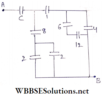
Solution:
The two capacitors of capacitance 6μF and 12μF are connected in series. If C1 is their equivalent capacitance, then
⇒ \(C_1=\frac{6 \times 12}{6+12}=4 \mu \mathrm{F}\)
This C1 and the capacitor of capacitance 4μF are connected in parallel. If C2 is their equivalent capacitance, then
C2 = 4 + 4
= 8μF
Again C2 and the capacitor of capacitance 1μF are connected in series. If C3 be their equivalent capacitance, then
⇒ \(C_3=\frac{8 \times 1}{8+1}=\frac{8}{9} \mu \mathrm{F}\)
On the other side, the capacitors of capacitance 2μF each arein parallel. If C4 is their equivalent capacitance, then
C4 = 2 + 2
= 4μF
Again C4 and the capacitor of capacitance 8mmF are in series.If C5 be their equivalent capacitance, then
⇒ \(C_5=\frac{4 \times 8}{4+8}=\frac{8}{3} \mu \mathrm{F}^{\prime}\)
Now C3 and C5 are in parallel combination. Their equivalent capacitance is given by,
⇒ \(C_6=\frac{8}{9}+\frac{8}{3}=\frac{32}{9} \mu \mathrm{F}\)
This C6 and C are in series and their equivalent capacitance = 1μF.
∴ \(\frac{\frac{32}{9} \times C}{\frac{32}{9}+C}=1\)
or, \(\frac{32}{9} \times C=\frac{32}{9}+C\)
or, \(\frac{23}{9} C=\frac{32}{9}\)
or, \(C=\frac{32}{23}=1.39 \mu \mathrm{F}\)
Example 16. Three capacitors A, B, and C are connected in such a way that their equivalent capacitance Is equal to the capacitance of B. The capacitances of A and B are 10μF and 30μF respectively and C ≠ 0. Determine three possible values of C and also show how the capacitors are to be connected in the three cases.
Solution:
The capacitor B cannot be joined in parallel to any combination of the capacitors A and C because in that case, the equivalent capacitance will be greater than the capacitance of B. The following three combinations are possible.
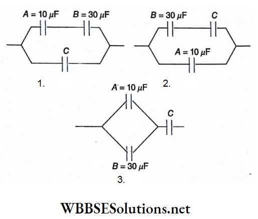
1. A and B are connected in series. Now C is connected in parallel with the series combination of A and B.
According to the question,
⇒ \(\frac{10 \times 30}{10+30}+C=30\)
or, \(\frac{300}{40}+C=30\)
or, C = 22.5μF
2. B and C are connected in series. Now A is connected in parallel with the series combination of B and C.
According to the question,
⇒ \(\frac{30 \times C}{30+C}+10=30\)
or, \(\frac{30 \times C}{30+C}=20\)
or, C = 60μF
3. A and B are connected in parallel. Now C is connected in series with the parallel combination of A and B.
According to the question,
⇒ \(\frac{40 \times C}{40+C}=30\)
or, 3(40 + C) = 4C
or, C = 120μF
Example 17. Two parallel plate capacitors of capacitances C and 2C are connected parallel and charged to a potential difference V. The battery then disconnected and the region between the plates of the capacitor C is completely filled with a material of dielectric constant k. What is the potential difference across the capacitors now?
Solution:
If charges Q1 and Q2 are given to the capacitors, then
Q1 = CV; Q2 = 2CV
∴ Total charge = Q1 + Q2
= CV+ 2CV
= 3CV
If the region between the plates of capacitor C is filled with a material of dielectric constant K, its capacitance will be kC.
∴ Total capacitance = kC+2C = (k + 2)C
∴ Potential difference across the capacitors = \(\frac{3 C V}{(\kappa+2) C}=\frac{3 V}{\kappa+2}\)
Class 12 WBCHSE Physics Capacitor Concepts
Example 18. A potential difference of 20 V is applied across a parallel combination of three Identical capacitors. If the total charge in the combination is 30 C, determine the capacitance of each capacitor. What will be the charge of the series combination of these three capacitors with the same potential difference?
Solution:
Let the capacitance of each capacitor be C.
The potential difference across each capacitor when they are connected in parallel combination, V = 20 V.
∴ Charge on the three capacitors,
Q1 = Q2 = Q3 = CV
∴ Q1 + Q2 + Q3 = 3CV
or, 30 = 3 X C X 20
= 60C
or, C = \(\frac{1}{2}\)
= 0.5F
∴ The capacitance of each capacitor = 0.5 F
In the second case when the capacitors are connected in series, let us suppose that the equivalent capacitance is C’
∴ \(\frac{1}{C^{\prime}}=\frac{1}{C}+\frac{1}{C}+\frac{1}{C}=\frac{3}{C}\)
or, \(C^{\prime}=\frac{C}{3}=\frac{0.5}{3}=\frac{1}{6} \mathrm{~F}\)
In this case, the total charge of the combination,
⇒ \(Q_i^{\prime}=C^{\prime} V\)
= \(\frac{1}{6} \times 20\)
= \(\frac{10}{3}\)
= 3.33 C
Example 19. The capacitance of a parallel plate air capacitor is C. Now, half the areas of its plates are vertically dipped in oil of dielectric constant 1.6. What would be Its capacitance?
Solution:
The upper half would still be an air capacitor. As the plate areas are halved, its capacitance, C1 = \(\frac{C}{2}\). The lower half, immersed in oil, would have a capacitance, C2 = \(\frac{kC}{2}\). C1 and C2 would form a parallel combination; the equivalent capacitance,
\(C^{\prime}=C_1+C_2=\frac{C}{2}+\frac{\kappa C}{2}=\frac{C}{2}(1+\kappa)\)
= \(\frac{C}{2}\)(1 + 1.6)
= 1.3C
Example 20. Each of the plates of a parallel plate capacitor is a circular disc of radius 5 cm. Find out its capacitance if the separation between the plates is 1 mm.
Solution:
The radius of each plate, r = 5 cm = 0.05 m.
Separation between the plates, d = 1 mm = 0.001 m.
∴ Capacitance, \(C=\frac{\epsilon_0 \alpha}{d}=\frac{\epsilon_0 \pi r^2}{d}\)
= \(\frac{\left(8.85 \times 10^{-12}\right) \times 3.14 \times(0.05)^2}{0.001}\)
= 6.95 X 100-11 F
= 69.5 pF
Example 21. A 2μF capacitor is charged to a potential of 20 V. Another 3μF uncharged capacitor is connected in parallel with the first capacitor. What would be the minimum potential difference of the combination? Find out the charges on the two capacitors
Solution:
Initially, the charge on the first capacitor,
Q1 = C1V1
= (2 x 10-6) x 20
= 40 x 10-6 C
and charge on the second capacitor, as it was uncharged, Q2 = 0.
∴ Net charge, Q = Q1 + Q2
= 40 x 10-6 C
Equivalent capacitance of the parallel combination,
C = C1 + C2
= (2 + 3)μF
= 5 X 10⁻⁶ F
∴ Terminal potential difference of the combination,
⇒ \(V=\frac{Q}{C}=\frac{40 \times 10^{-6}}{5 \times 10^6}=8 \mathrm{~V}\)
Charge on the first capacitor,
Q1 = C1V
= (2 x 10-6)x 8
= 16 x 10-6 C
= 16μC
and charge on the second capacitor,
Q2 = C2V
= (3 X 10-6) X 8
= 24 X 10-6 C
= 24pC
Class 12 WBCHSE Physics Capacitor Concepts
Example 22. A 20μF capacitor is charged to a potential of 20 V and is then connected to an uncharged 10μF capacitor. Find out the common potential and the ratio of the energies stored in the two capacitors.
Solution:
Here, the capacitance of the first capacitor,
C1 = 20μF
= 20 x 10-6 F
The capacitance of the second capacitor,
C2 = 10μF
= 10 x 10-6 F
Initially, the charge on the first capacitor,
Q1 = C1V1
= (20 X 10-6) X 20
= 400 X 10-6 C
and the charge on the second capacitor, as it was uncharged, Q2 = 0.
∴ Net charge, Q = Q1 + Q2
= 400 x 10-6 C
A parallel combination of the capacitors attains a common potential, say V.
Equivalent capacitance,
C = C1 + C2
= (20 + 10) x 10-6 F
= 30 x 10-6 F
⇒ \(V=\frac{Q}{C}=\frac{400 \times 10^{-6}}{30 \times 10^{-6}}=\frac{40}{3}\)
= 13.33V
The ratio of the energies stored in the two capacitors is,
⇒ \(\frac{E_1}{E_2}=\frac{\frac{1}{2} C_1 V^2}{\frac{1}{2} C_2 V^2}=\frac{C_1}{C_2}=\frac{20}{10}=\frac{2}{1}\)
Example 23. How should three capacitors of capacitances 3μF, 3μF and 6μF, be connected to get an equivalent capacitance of 5μF?
Solution:
For a parallel connection of all three capacitors, the 1 equivalent capacitance = 3 + 3 + 6
= 12μF; it is greater than 5μF.
Again, for a series connection, if the equivalent capacitance is C, then
⇒ \(\frac{1}{C_s}=\frac{1}{3}+\frac{1}{3}+\frac{1}{6}=\frac{5}{6}\)
or, \(C_s=\frac{6}{5}=1.2 \mu \mathrm{F}\) ; it is less than 5μF.
So, the above two connections are not applicable. Then, the following four arrangements are possible.
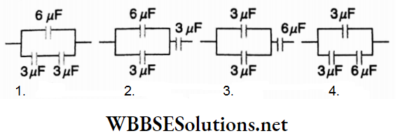
Now, for arrangement (1), the equivalent capacitance is clearly greater than 6μF; so it cannot be 5μF.
For the arrangement (2), equivalent capacitance
= \(\frac{(6+3) \times 3}{(6+3)+3}=2.25 \mu \mathrm{F}\)
For the arrangement (3), equivalent capacitance
= \(\frac{(3+3) \times 6}{(3+3)+6}=3 \mu \mathrm{F}\)
For the arrangement (4), equivalent capacitance
= \(3+\frac{3 \times 6}{3+6}=5 \mu \mathrm{F}\)
So, the arrangement (4) represents the desired connection.
Class 12 WBCHSE Physics Capacitor Concepts
Example 24. The capacitance of a parallel plate capacitor with plate area A and separation s is C. The space between the plates is filled with two wedges of dielectric constants k1 and k2 Find the capacitance of the resultant capacitor.
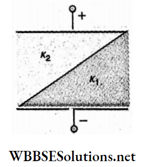
Solution:
Let the length of the capacitor plates be l and width b.
Area of each plate, A = lb
Now consider a small element of the capacitor of width dx at a distance x from the end. Its area, dA = bdx
The capacitance of this small element
⇒ \(d C=\frac{\epsilon_0 d A}{\frac{y}{\kappa_1}+\frac{s-y}{\kappa_2}}\)
According,
⇒ \(\frac{y}{x}=\frac{s}{l}=\tan \theta\)
∴ \(d C=\frac{\epsilon_0 b d x}{\frac{x \tan \theta}{\kappa_1}+\frac{s-x \tan \theta}{\kappa_2}}\)
∴ \(C=\int_0^l d C=\int_0^l \frac{\epsilon_0 b(d x) \kappa_1 \kappa_2}{\kappa_2 x \tan \theta+\kappa_1(s-x \tan \theta)}\)
Putting tanθ = \(\frac{s}{l}\)
⇒ \(C=\int_0^l \frac{\epsilon_0 A \kappa_1 \kappa_2 d x}{s \kappa_2 x+(l-x) s \kappa_1}=\frac{\epsilon_0 A \kappa_1 \kappa_2}{s\left(\kappa_2-\kappa_1\right)} \log _e \frac{\kappa_2}{\kappa_1}\)
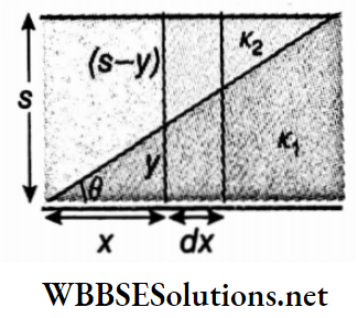
Examples of Capacitor Calculations
Example 25. Consider a parallel plate capacitor of plate separation d. Each plate has the length l and the width a. A dielectric slab of permittivity e and thickness d is partially inserted between the plates. The plates are kept at a constant potential difference V. If x is the length of the dielectric slab within the plates, determine the force exerted on the slab.
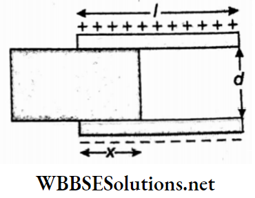
Solution:
As per the diagram, the system may be regarded as the parallel combination of two capacitances C1 and C2. The part containing the dielectric of permittivity e has capacitance q and the other part (through free space) has capacitance C2.
Hence, \(C_1=\frac{\epsilon a x}{d}\)
and \(C_2=\frac{\epsilon_0 a(l-x)}{d}\)
∴ Equivalent capacitance is,
⇒ \(C=C_1+C_2\)
= \(\frac{a}{d}\left[\left(\epsilon-\epsilon_0\right) x+\epsilon_0 l\right]\)
Now electrostatic energy of the system is
⇒ \(U=\frac{1}{2} C V^2\)
= \(\frac{1}{2} \frac{a}{d}\left[\left(\epsilon-\epsilon_0\right) x+\epsilon_0 l\right] V^2\)
∴ V is constant, the force experienced by the slab is,
⇒ \(F_x=\frac{d U}{d x}\)
= \(\frac{a}{2 d}\left(\epsilon-\epsilon_0\right) V^2\)
Example 26. A parallel plate capacitor of capacitance C Is connected to a battery to charge to a potential V. Similarly, another capacitor of capacitance 2C is charged to a potential 2V. Now the batteries are removed, and the two capacitors are connected in parallel by joining the positive plate of one with the negative plate of the other. Find out the final energy of the system.
Solution:
Charge on the first capacitor of capacitance C and connected to the battery of voltage V is,
Q1 = CV
Similarly charge on the second capacitor,
Q2 = (2C) x (2 V)
= 4CV
Since the plates of opposite polarity are connected together, the common potential is,
⇒ \(V^{\prime}=\frac{Q_2-Q_1}{C_1+C_2}=\frac{4 C V-C V}{C+2 C}=V\)
Now equivalent capacitance,
C’ = C+2C
= 3C
So final energy of the configuration,
⇒ \(U_f=\frac{1}{2} C^{\prime}\left(V^{\prime}\right)^2\)
= \(\frac{1}{2} \times 3 C \times V^2\)
= \(\frac{3}{2} C V^2\)
Capacitance Derivations For Class 12 WBCHSE
Example 27. In the circuit, the values of the capacitances of the four capacitors are C1 = C, C2 = 2C, C3 = 3C and C4 = 4C. Find out the ratio between the charges on C2 and C4

Solution:
Here C1 = C, C2 = 2C, C3 = 3C and C4 = 4C.
C1, C2, and C3 are connected in series, so equivalent capacitance is,
⇒ \(\frac{1}{C_{123}}=\frac{1}{C}+\frac{1}{2 C}+\frac{1}{3 C}=\frac{11}{6 C}\)
∴ \(C_{123}=\frac{6 C}{11}\)
Let q1, q2, q3 and q4 be the charges of the capacitors C1, C2, C3 and C4 respectively.
As C1, C2, and C3 are in series, the charge on them is the same.
∴ \(q_1=q_2=q_3=C_{123} \times V=\frac{6 C V}{11}\)
Again charge on capacitor C4 is,
Q4 = C4 x V
= 4CV
So, \(\frac{\text { charge on } C_2}{\text { charge on } C_4}=\frac{\frac{6 C V}{11}}{4 C V}\)
∴ \(\frac{q_2}{q_4}=\frac{6}{4 \times 11}=\frac{3}{22}\)
∴ q2: q4 = 3: 22
Example 28. Five capacitors, capacitance 10μF, form a network. The network is connected to a 100 V dc supply. Calculate the equivalent capacitance between A and B, and the charge accumulated in the network.
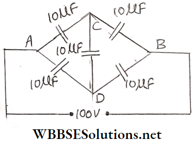
Solution:
The given network is a balanced bridge so the middle part (CD) does not play any role.
So equivalent capacitance of branch ACB is,
⇒ \(C_{A C B}=\frac{10 \times 10}{10+10}=5 \mu \mathrm{F}\) [∴ capacitors in branches AC and CB are in series]
Similarly equivalent capacitance of branch ADB is,
⇒ \(C_{A D B}=\frac{10 \times 10}{10+10}=5 \mu \mathrm{F}\)
∴ Equivalent capacitance for the whole network is,
Cwhole = (5 + 5)μF
= 10μF
Now charge accumulated in branch ACB is,
qACB = CACB x V
= 5 x 10-6 x 100C
and charge accumulated in branch ADB,
qADB = CADB x V
= 5 x 10-6 x 100 C
∴ Total charge accumulated in the whole network,
q = qACB + qADB
= 10 x 10-6 x 100 C
= 10-3 C
Example 29. In the network of the capacitance of each capacitor is 1μF. Determine the equivalent capacitance between P and Q.
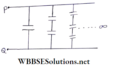
Solution:
Let C1, C2, C3, C4, …∞ be the capacitances of the capacitors contained in the first row, second row, third row, fourth row, and so on.
Since the capacitors are in series in each row, the equivalent capacitances for the rows are given by,
C1 = 1μF
⇒ \(C_2=\frac{1 \times 1}{1+1}=\frac{1}{2} \mu \mathrm{F}\)
⇒ \(\frac{1}{C_3}=\frac{1}{1}+\frac{1}{1}+\frac{1}{1}+\frac{1}{1}=4\)
∴ \(C_3=\frac{1}{4} \mu \mathrm{F}\)
Similarly,
⇒ \(\frac{1}{C_4}=\frac{1}{1}+\frac{1}{1}+\frac{1}{1}+\frac{1}{1}+\frac{1}{1}+\frac{1}{1}+\frac{1}{1}+\frac{1}{1}=8\)
∴ \(C_4=\frac{1}{8} \mu \mathrm{F}\)
Hence, the equivalent capacitance of the infinite number of rows,
⇒ \(C_{\mathrm{eq}}=C_1+C_2+C_3+C_4+\cdots+\infty\) [∵ they are connected in parallel]
∴ \(C_{\mathrm{eq}}=1+\frac{1}{2}+\frac{1}{4}+\frac{1}{8}+\cdots \infty\)
∴ Sum of the infinite geometric progression is given by,
⇒ \(C_{\mathrm{eq}}=\frac{1}{1-\frac{1}{2}}\)
∴ \(C_{\mathrm{eq}}=2 \mu \mathrm{F}\)
This is equivalent capacitance.
Capacitance Derivations For Class 12 WBCHSE
Example 30. A 0.1 F capacitor is charged by a 10 V battery. After disconnecting the battery, this charged capacitor is connected with an uncharged capacitor. If the charge is equally shared between the two, then what will be the energy stored in the two capacitors? Compare this energy with the energy stored initially in the first capacitor.
Solution:
Let C1 and C2 be the capacitances of the capacitors and their voltages be V1 and V2 respectively.
Given C1 = 0.1 F,
initially V1 = 10 V
and V2 = 0.
∴ The initial energy stored in the two capacitors is,
⇒ \(U_i=\frac{1}{2} C_1 V_1^2+\frac{1}{2} C_2 V_2^2\)
= \(\frac{1}{2}\) x 0.1 x (10)² + 0
= 5J
It Q is the initial charge on capacitor C1, its initial energy is,
⇒ \(U_i=\frac{Q^2}{2 C_1}\)
When the two capacitors are connected together, the charge is distributed equally, so the charge on each capacitor is \(\frac{Q}{2}\). Since the potential difference (in a parallel connection) across the two capacitors is also the same, it follows that their capacitances are equal.
Thus, C1 = C2 = C (say)
Also, Q1 = Q2 = \(\frac{Q}{2}\)
∴ The final energy stored in the two capacitors is
⇒ \(U_f=\frac{Q_1^2}{2 C_1}+\frac{Q_2^2}{2 C_2}=\frac{\left(\frac{Q}{2}\right)^2}{2 C}+\frac{\left(\frac{Q}{2}\right)^2}{2 C}=\frac{Q^2}{4 C}\)
But, \(U_i=\frac{Q^2}{2 C}, \text { hence } U_f=\frac{U_i}{2}=2.5 \mathrm{~J}\)
Thus, \(\frac{U_f}{U_i}=\frac{2.5}{5}=\frac{1}{2}\)
Concepts of Dielectric Materials in Capacitors
Example 31. The equivalent capacitance of two capacitors connected in series and in parallel are Cs and Cp respectively. Determine the capacitance of each capacitor.
Solution:
Let C1 and C2 be the values of the two capacitances.
According to the question,
C1 + C2 = Cp…(1)
⇒ \(\frac{C_1 C_2}{C_1+C_2}=C_s\)…(2)
From equations (1) and (2),
\(\frac{C_1 C_2}{C_p}=C_s\)
∴ \(C_2=\frac{C_p C_s}{C_1}\)
Using this value in equation (1)
⇒ \(C_1+\frac{C_p C_s}{C_1}=C_p \quad\)
or, \(C_1^2-C_p C_1+C_p C_s=0\)
∴ \(C_1=\frac{C_p \pm \sqrt{C_p^2-4 C_p C_s}}{2}\)
Using the positive sign (+) for C1, we have,
So, the two capacitances are,
⇒ \(\frac{1}{2}\left[C_p+\sqrt{C_p^2-4 C_p C_s}\right] \text { and } \frac{1}{2}\left[C_p-\sqrt{C_p^2-4 C_p C_s}\right]\)
Capacitance Derivations For Class 12 WBCHSE
Unit 1 Electrostatics Chapter 4 Capacitance And Capacitor Different Types Of Capacitors
Nowadays, different types of capacitors are used for practical purposes. Some of them are discussed below.
Mica capacitor or block capacitor:
This is actually a parallel combination of a few parallel plate capacitors having a fixed capacitance. It consists of a number of metal sheets with mica as a dielectric between them. The alternate sheets are connected to A while the others are to B. If a potential difference is applied between A and B, the capacitor becomes charged.
If α be the area of each metal plate, d is the distance between two plates, K is the dielectric constant of mica and n is the number of metal plates, then the capacitance of such a capacitor in SI is given by
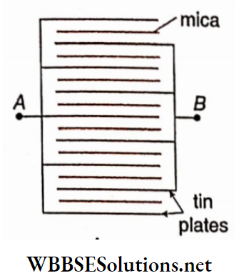
⇒ \(C=\frac{(n-1) \kappa \epsilon_0 \alpha}{d}\)
This capacitor looks like a block. So it is often called a block capacitor. This type of capacitor is mainly used in wireless receiving sets.
Paper capacitor: Paper coated with paraffin is a suitable dielectric. In between two aluminum or tin foils, paraffin-waxed paper sheets are inserted. The foils are then rolled into a cylindrical shape for the economy of space. This type is essentially a single parallel plate capacitor. It is cheaper than a mica capacitor. Of course one of its disadvantages is that it cannot work at high potential difference.
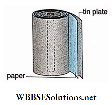
In low-voltage ac circuits, having semiconductor diodes and transistors in particular, paper capacitors are widely used.
Variable air capacitor: It is also one type of parallel plate capacitor whose capacitance can be varied at will. It consists of two sets (F and M) of parallel plates made of aluminum or brass. The set is fixed while the other set M can be turned with the help of a knob K.
As the knob turns, the set M either moves into the spacings of the set F or comes out of them, thereby changing the area of overlap of tire plates. Since the capacitance of a capacitor depends on the area of overlap of the plates, the capacitance also changes.
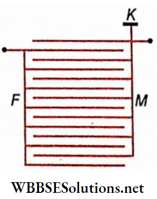
It is used in radio sets or wireless receiving sets and other electronic instruments where variation of capacitance is required. Electrolytic capacitor: It consists of a pair of aluminum plates partly immersed into a solution of ammonium borate [NH4B5O6].
The two aluminum plates are connected to the positive and negative terminals of a source of steady current. Due to electrolysis, a fine layer (10-6 cm) of aluminum oxide [Al2O3] is formed on the positive plate.
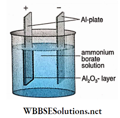
This layer acts as a dielectric medium. The solution of ammonium borate acts as an extension of the other plate. Since the capacitance of the capacitor is inversely proportional to the thickness of the dielectric and the thickness of the aluminum oxide layer is very small, the capacitor has a large capacitance, often a few thousand microfarads.
The plate on which aluminum oxide is deposited must be connected to the positive potential. Otherwise, the capacitor would be damaged. For this reason, the anode plate is marked with a + sign or a red dot.
Further, the maximum voltage applicable is restricted by the thickness of the oxide layer. This is also marked on the capacitor. Higher voltage would break the layer and destroy the device. Electrolytic capacitors are largely used as filters in rectifier circuits.
Electrostatic Machines
Classification of Electrostatic Machines:
Electrostatic machines can generate large quantities of electric charges rapidly. These machines are also used to set up high-potential differences. Electrostatic machines are of two types
- Frictional machine
- Induction machine.
Frictional machines were not very effective. So after the invention of induction machines, frictional machines became obsolete. The principle of action of induction machines depends on the principle of electrostatic induction. In this chapter, we shall discuss a familiar electrostatic machine known as the Van de Graaff generator.
Van de Graaff Generator:
In 1931, Van de Graaff invented this machine. With the help of this machine, very high potential difference (up to a few million volts) can be produced. The principle of action of this machine is based on the discharging action of points and on the property of a collection of charges of a hollow conductor. This machine is very useful at atomic research centers. At present, many changes and modifications of this machine have been introduced.
Description: The sketch of a Van de Graaff generator. A and B are two hollow spherical conductors.
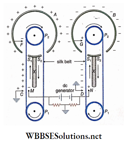
These are placed on two big insulating stands (X, X). P1 and P2 form two pairs of pulleys. The pulleys are situated at the centers of the spherical conductors and are connected by two electric motors.
Silk or rubber belt moves in the path shown by arrows along the body of each pair of pulleys. The belt enters the spherical conductor through the hole Sx and comes out through the hole S2. C, D, F, and G are four pointed conductors. The pointed ends are directed towards the belt.
The positive charge is supplied to the small sphere (N) placed in front of the pointed conductor D and the negative charge to the small sphere (M) placed in front of the pointed conductor C with the help of a dc generator. The pointed conductors F and G are connected with the spheres A and B respectively.
Working principle:
A positive charge on the small sphere (N) in front of the pointed conductor D induces a negative charge on D and the induced positive charge, being free, moves to the earth. The pointed conductor D discharges the negative charge to the belt in front of it.
The belt, being a non-conductor, does not distribute the charge all over its body; it remains connected to one place. The belt carries the charge upwards and when the charge comes near the pointed conductor G, it induces a positive charge on G and a negative charge on sphere B. Very soon the positive charge on G gets neutralised by the negative charge on the belt. So sphere B is charged with negative electricity.
Similarly, due to the negative charge on the small sphere (M) in front of the pointed conductor C, sphere A is charged with positive electricity.
Discharge of electricity and its remedy:
Due to the continuous movement of the belt by the electric motor, a large quantity of charge accumulates on the two spheres A and B and the potential difference between them increases quickly.
Due to continuous increases in the potential difference between the two spheres, an electric discharge may start in the neighboring air, as air cannot bear high potential differences under normal pressure.
To avoid pointed-end discharge, the spheres and the belts are made very smooth. The whole instrument is installed in a large metallic case connected to the earth and air inside the case is pumped out with the help of an exhaust pump.
Next, the entire case is filled up with nitrogen or freon gas under high pressure. Because, even under high potential difference, the tendency of nitrogen or freon molecules to be ionized, is low.
Uses:
1. Production of high energy charged particles, in nuclear research.
2. Production of hard X-rays. In Science City, Kolkata there is a Van de Graaff generator for display
Unit 1 Electrostatics Chapter 4 Capacitance And Capacitor Synopsis
The capacitance of a conductor is equal to the charge necessary to increase its potential by unity.
Units of capacitance:
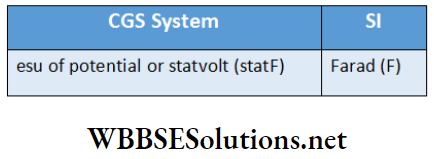
- If 1 esu of charge raises the potential of a conductor by 1 esu, the capacitance of the conductor is defined as 1 esu of capacitance or 1 stat farad (statF).
- If 1 coulomb of charge is required to raise the potential of a conductor by 1 volt, the capacitance of the conductor is defined as 1 farad.
- 1 C = 3 x 10⁹ esu of charge; 1 V = \(\frac{1}{300}\) esu ofpotential difference; so,
- IF = \(\frac{1C}{1V}\) = 9 x 10¹¹ esu of capacitance or statF
- An arrangement by which the capacitance of an insulated charged conductor placed in the vicinity of another conductor (usually earthed) is increased artificially, is called a capacitor.
- When a capacitor is connected to a battery, charges begin to accumulate on it. This is called the charging of a capacitor. After disconnection of the battery, if any conduction occurs between the two plates of the capacitor, it begins to lose charge. This is called the discharging of a capacitor.
- The potential difference between the two conducting plates of a capacitor is called the potential of a capacitor.
- The capacitance of a capacitor is equal to the charge given to the insulated conductor of the capacitor to raise its potential by unity.
- Dielectric is an insulator. Examples—are air, paraffin, glass, sulphur, mica, ebonite, etc.
- The dielectric constant of an insulator,
- k = \(\frac{capacitance of a capacitor with the dielectric ns the intervening medium}{capacitance of the same capacitor with vacuum ns the intervening medium}\)
- Effectively, the dielectric constant of air or vacuum is 1.
- To charge a capacitor, a certain amount of work is to be done. The energy spent for doing that work remains stored as potential energy in the electric field between the two plates of the capacitor.
- For a series combination, the equivalent capacitance is always less than any of the capacitances in the series.
- The equivalent capacitance of capacitors joined in parallel is greater than any of the capacitances in the combination.
- Electrostatic machines can generate large quantities of electric charge rapidly. These machines are also used to set up high-potential differences.
- Electrostatic machines arc of two types:
- Frictional machine and
- Induction machine.
- The working principle of an induction machine is based on electrostatic induction. Van de Graaff generator is an electrostatic machine of this type.
- With the help of a Van de Graaff generator, a very high potential difference (up to a few million volts) can be produced.
- The working principle of a Van de Graaff generator depends on the discharging action of points and on the property of collection of charge by hollow conductors.
- Van de Graaff generator is used
- To produce high energy charged particles which are required for nuclear research
- To produce hard X-rays.
- If charge Q given to a conductor raises its potential by V,then Q ∝ For, Q = CVwhere C is the capacitance of the conductor.
- The capacitance of a spherical conductor,
C = 4π∈0kR (in SI)
- [Here, R = radius of spherical conductor, K = dielectric constant of the surrounding medium]
- The capacitance (in CGS) of a spherical conductor air or vacuum is numerically equal to its radius in centimetres.
- The energy of a charged conductor,
⇒ \(U=\frac{1}{2} Q V\)
= \(\frac{1}{2} C V^2\)
= \(\frac{1}{2} \frac{Q^2}{C}\)
where Q = charge, V = potential.
- If two conducting spheres of radii rx and r2, connected by a conducting wire, are given a charge Q, then charges on the spheres are,
⇒ \(Q_1=Q \cdot \frac{r_1}{r_1+r_2} ; Q_2=Q \cdot \frac{r_2}{r_1+r_2}\)
- Two conductors having capacitances C1 and C2, are charged to potentials V1 and V2. If they are connected, the common potential becomes,
⇒ \(V=\frac{C_1 V_1+C_2 V_2}{C_1+C_2}\)
= \(\frac{Q_1+Q_2}{C_1+C_2}\)
Q1 and Q2 are their charges before connection. Loss of energy due to sharing of charge
⇒ \(\frac{1}{2} \frac{C_1 C_2}{C_1+C_2}\left(V_1-V_2\right)^2\)
- The capacitance of a parallel plate capacitor,
⇒ \(\left.C=\frac{\kappa \epsilon_0 \alpha}{d} \text { (in } \mathrm{SI}\right)\)
⇒ \(C=\frac{\kappa \alpha}{4 \pi d} \text { (in CGS system) }\)
where α = area of each plate; d = distance between the plates.
If a combination is formed by connecting alternately n number of equispaced parallel plates, the capacitance of such a block capacitor
⇒ \(C=\frac{(n-1) \kappa \epsilon_0 \alpha}{d}(\text { in SI) }\)
⇒ \(C=\frac{(n-1) k \alpha}{4 \pi d} \text { (in CGS system) }\)
The capacitance of a parallel plate capacitor with compound dielectric,
⇒ \(C=\frac{\epsilon_0 \alpha}{\frac{d_1}{\kappa_1}+\frac{d_2}{\kappa_2}} \text { (in SI) }\)
where k1 and k2 are the dielectric constants of the dielectrics of thickness d1 and d2, respectively.
Energy stored in a charged capacitor,
⇒ \(U=\frac{1}{2} \cdot \frac{Q^2}{C}=\frac{1}{2} C V^2=\frac{1}{2} Q V\)
[where Q = charge of the capacitor and V = potential difference between the capacitorplates]
The potential energy of a parallel plate capacitor
⇒ \(U=\frac{1}{2} \cdot \frac{\alpha \sigma^2 d}{\kappa \epsilon_0} \text { (in SI); }\)
⇒ \(U=\frac{2 \pi \sigma^2 \alpha d}{\kappa} \text { (in CGS system) }\)
Energy density between the capacitor plates,
⇒ \(u=\frac{1}{2} \kappa \epsilon_0 E^2\)
[where E = electric field between the two plates of the capacitor, k = dielectric constant of the medium between the plates.]
For vacuum or air, K = 1.
Then u = \(\frac{1}{2} \epsilon_0 E^2\)
- For a series combination of capacitors, the equivalent capacitance is given by the following equation:
⇒ \(\frac{1}{C}=\frac{1}{C_1}+\frac{1}{C_2}+\cdots+\frac{1}{C_n}=\sum_1^n \frac{1}{C_n}\) [n = number of capacitors in series]
- The equivalent capacitance of the capacitors joined in parallel,
⇒ \(C=C_1+C_2+\cdots+C_n=\sum_1^n C_n\) [n = number of capacitors in parallel]
- Charge in different quantities due to the Introduction of a dielectric slab of dielectric constant K between the plates of a parallel plate capacitor after the capacitor has been chanted with the help of a battery.
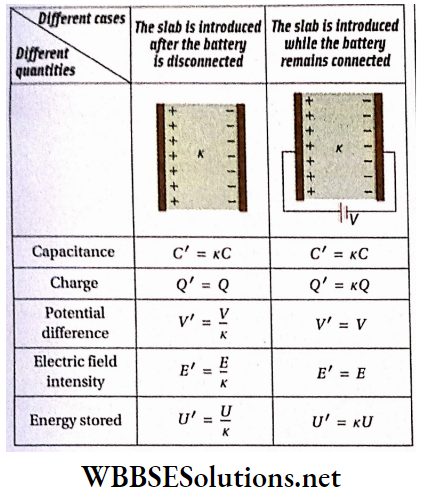
- In n number of similar electrically charged drops coalesce to form a larger drop,
- Charge of the large drop =nx charge of each small drop
- Capacitance of eh large drop = n1/3 x capacitance of each small drop
- The surface potential of the large drop = n2/3 x surface potential of each small drop
- The energy of the large drop = n5/3 x energy of each small drop
- Surface density of charge of the large drop = n1/3 x surface density of each small drop
- A capacitor of capacitance C can be charged by connecting
it is in series with a battery of emf E and a resistance R. The charge on the capacitor after a time t,
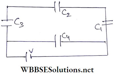
⇒ \(q=C E\left(1-e^{-\frac{t}{R C}}\right)=q_0\left(1-e^{-t / \tau}\right)\)
Maximum charge on the capacitor, q0 = CE
The time constant of the charging circuit, \(\tau\) = RC
- In the circuit, when the key Ky is pressed, the battery of emf E is connected in series with the capacitor C and resistor R, and the capacitor starts charging. After some time, the key Ky is switched off and the key K2 is pressed, then the capacitor starts discharging
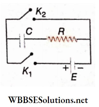
The charge on the capacitor after a time t,
⇒ \(q=C E e^{-\frac{t}{C R}}=q_0 e^{-t / \tau}\)
The time constant of the discharging circuit, \(\tau\) = RC
Unit 1 Electrostatics Chapter 4 Capacitance And Capacitor Very Short Questions and Answers
Question 1. What is the name of the physical quantity whose unit is coulomb volt-1?
Answer: Capacitance
Question 2. What is the radius of a conducting sphere of capacitance 10μF?
Answer: 9 cm
Question 3. Two copper spheres of the same radius, one of them being hollow and the other solid, are charged to the same potential. Which of them does contain a greater amount of charge?
Answer: Both contain the same amount of charge
Question 4. If a charged soap bubble expands, what will be the change in its potential?
Answer: The potential will decrease
Question 5. What is the unit of dielectric constant?
Answer: No unit
Question 6. The surface area of a conducting sphere is 10.18 cm2. If it is placed in the air, what will be its capacitance in the picofarad?
Answer: 1
Question 7. n small drops of the same size are initially at the. same potential. They coalesce to form a big drop. What is the ratio of the capacitance of this big drop to that of any of these small drops?
Answer: n1/3
Question 8. Two conductors of capacitances C1 and C2 are connected by a conducting wire. Some amount of charge is given to the system. How is the ratio of charges acquired by the conductors related to their capacitances?
Answer: C1/C2
Question 9. Two conductors, of capacitances C1 and C2, initially have charges q1 and q2 at potentials V1 and V2, respectively. They are now connected by a thin conducting wire. What quantity the net energy loss of the system would be proportional to?
Answer: (V1-V2)2
Question 10. Two spheres of radii r and 2r have charges 2q and q on them, respectively. If they are connected by a copper wire, what will be the amount of charge flowing through the wire?
Answer: q
Question 11. A capacitor is marked as 0.05μF 200V. What is the maximum charge it can accumulate without being damaged?
Answer: 10-3C
Question 12. What is the dielectric constant of conducting materials?
Answer: Infinite
Question 13. What happens when the space between the two plates of a capacitor is filled with a conducting material?
Answer: It will be discharged completely
Question 14. What is the permittivity ofmica if its dielectric constant is 5.4?
Answer: 4.78 x 10⁻¹¹C2N-1m-2
Question 15. What is the unit of the permittivity of vacuum, ∈0?
Answer: C2.N-1 m-2
Question 16. Write down the dimensional formula of ∈0
Answer: M-1L-3T4l2
Question 17. s the permittivity of any medium greater or less than that of vacuum?
Answer: Greater
Question 18. If a dielectric is placed in an electric field, what change in the intensity of the electric field takes place inside the dielectric?
Answer: Electric field intensity decreases
Question 19. The space between the two plates of a parallel plate air capacitor is filled with an insulator. What will be the nature of the change in its capacitance?
Answer: Increase
Question 20. The space between the two plates of an isolated charged parallel plate air capacitor is filled with an insulator. What will be the nature of the change of the charge accumulation?
Answer: No change
Question 21. In a parallel plate capacitor, the capacitance increases from 4μF to 80μF when a dielectric medium is introduced between the plates. What is the dielectric constant of the medium?
Answer: 20
Question 22. What will be the effect on the capacity of a parallel plate capacitor when the area of each plate is doubled and the distance between them is also doubled?
Answer: No change
Question 23. The distance between the plates of a parallel plate capacitor is d. A metal plate of thickness d/2 is placed between the plates. What will be its effect on the capacitance of the system?
Answer: Capacitance Is Doubled
Question 24. Two protons A and B are placed between two parallel plates having a potential difference V. Will these protons experience equal or unequal forces?
Answer: Equal forces
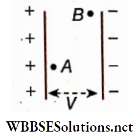
Question 25. How can a capacitance of 10μF be designed from a few supplied 2μF capacitors?
Answer: Five of them are to be connected in parallel
Question 26. How can two capacitors be connected so that the charges on them are equal?
Answer: In series
Question 27. How can two capacitors be connected so that the potential differences between their plates are equal?
Answer: In parallel
Question 28. A combination is formed by connecting alternately n number of equidistant parallel plates. The capacitance between any two consecutive plates is C. What will be the equivalent capacitance of the combination?
Answer: (n-1)C
Question 29. Two charged conductors, each of which is effectively a capacitor, are connected by a conducting wire. Which type of combination of capacitors is this—series or parallel?
Answer: Parallel
Question 30. Three capacitors of equal capacitance, when connected in series, have a net capacitance C1. When connected parallel, they have a net capacitance of C2. What is the value of C1/C2?
Answer: 1/9
Question 31. Two plates of an isolated charged capacitor are connected by a copper wire. What will happen to the energy stored in the capacitor?
Answer: It will be zero
Question 32. The separation between the two plates of an isolated charged parallel plate air capacitor is d. The capacitor stores an energy U. Now a metal plate of thickness d/2 and of area equal to that of the capacitor plates is introduced in the intermediate space. What will be the energy stored in the capacitor?
Answer: U/2
Question 33. The separation between the two plates of an isolated charged parallel plate air capacitor is d. The capacitor stores an energy U. Now an insulating plate of thickness d/2, of dielectric constant K, and of area equal to that of the capacitor plates is introduced in the intermediate space. What will be energy stored in the capacitor?
Answer: \(\frac{K+1}{2 K} U\)
Question 34. n capacitors, each of capacity C, are connected in parallel and to a source of V volt. What will be the energy storedin the arrangement?
Answer: \(\frac{1}{2} n C V^2\)
Question 35. n capacitors, each of capacity C, are connected in series and to a source of V volt. What will be the energy storedin the arrangement?
Answer: \(\frac{1}{2 n} C V^2\)
Unit 1 Electrostatics Chapter 4 Capacitance And Capacitor Fill In The Blanks
1. The radius of the earth is 6400 km. Its capacitance in microfarad is 711.1
2. The intensity of the electric field in a dielectric decrease due to electric polarisation
3. A metal plate of negligible thickness is introduced between the two plates of a parallel plate air capacitor. The capacitance will remain the same
4. The distance between the two plates of an isolated charged parallel plate air capacitor is increased. The potential difference between the plates will increase
5. The space between the plates of a capacitor is filled up with a liquid of specific inductive capacity K. The capacitance will change by a factor of k
6. V a de Graaff generator is used to produce hard X-ray
Unit 1 Electrostatics Chapter 4 Capacitance And Capacitor Assertion Reason Type
Direction: These questions have Statement 1 and Statement 2. Of the four choices given below, choose the one that best describes the two statements.
- Statement 1 is true, statement 2 is true; Statement 2 is, a correct explanation for statement 1.
- Statement 1 is true, Statement 2 is true; Statement 2 is not a correct explanation for Statement 1.
- Statement 1 is true, statement is false.
- Statement 1 is false, and Statement 2 is true.
Question 1.
- Statement 1: Two capacitors of the same capacity are first connected in parallel and then in series. The ratio of equivalent capacitances in two cases is 2: 1.
- Statement 2: The equivalent capacitance is less than any of the capacitances in series.
Answer: 4. Statement 1 is false, Statement 2 is true.
Question 2.
- Statement 1: If the distance between the parallel plates of a capacitor is halved and the dielectric constant is made three times then the capacitance becomes 6 times.
- Statement 2: The capacitance of the capacitor does not depend on the nature of the material of the plates of the capacitor.
Answer: 2. Statement 1 is true, Statement 2 is true; Statement 2 is not a correct explanation for Statement 1.
Question 3.
- Statement 1: The larger the sphere, the larger is its capacity, and the smaller the sphere, the smaller is its capacity.
- Statement 2: The capacitance of a spherical conductor is directly proportional to its radius.
Answer: 1. Statement I is true, statement II is true; Statement 2 is, a correct explanation for statement I.
Question 4.
- Statement 1: Dielectric has no significance in a parallel plate capacitor.
- Statement 2: A Dielectric is an insulator that can be easily polarised on the application of an electric field.
Answer: 4. Statement 1 is false, Statement 2 is true.
Question 5.
- Statement 1: The force with which one plate of a parallel plate capacitor is attracted towards the other plate is equal to the square of surface charge density per e per unit area.
- Statement 2: The total amount of charge that resides, on the unit surface area is known as surface charge density.
Answer: 4. Statement 1 is false, Statement 2 is true.
Question 6.
- Statement 1: The capacity of a conductor, under given circumstances, remains constant irrespective of the charge present on it.
- Statement 2: Capacity depends on the size and shape of the conductor and also on the surrounding medium.
Answer: 1. Statement 1 is true, statement 2 is true; Statement 2 is, a correct explanation for statement 1.
Question 7.
- Statement 1: A dielectric slab is inserted between the ‘ plates of an isolated charged capacitor. The charge on the capacitor will remain the same.
- Statement 2: Charge on an isolated system is conserved.
Answer: 1. Statement 1 is true, statement 2 is true; Statement 2 is, a correct explanation for statement I.
Question 8.
- Statement 1: The potential energy of a capacitor is obtained at the cost of chemical energy from the battery used for charging the capacitor.
- Statement 2: In a battery potential energy is converted to chemical energy.
Answer: 3. Statement 1 is true, the statement is false.
Capacitance Derivations For Class 12 WBCHSE
Unit 1 Electrostatics Chapter 4 Capacitance And Capacitor Match The Columns
Question 1. A capacitor of capacitance C is charged to a potential V. Now, it is connected to a battery of emf E. Based on this information match the entries of column 1 with entries of column 2 in the following table.
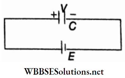
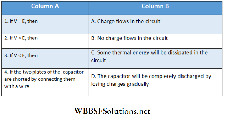
Answer: 1-B, 2-C, 3-A, 4-D
Question 2. Mathematical expressions of some physical quantities and their corresponding units are given in column 1 and column 2 respectively.
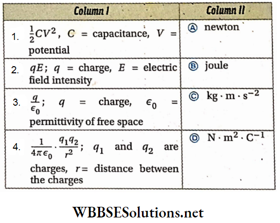
Answer: 1-B, 2-A,C, 3-D, 4-A,C
Question 3.
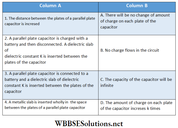
Answer: 1-A, 2-A,B, 3-D, 4-C
Question 4.
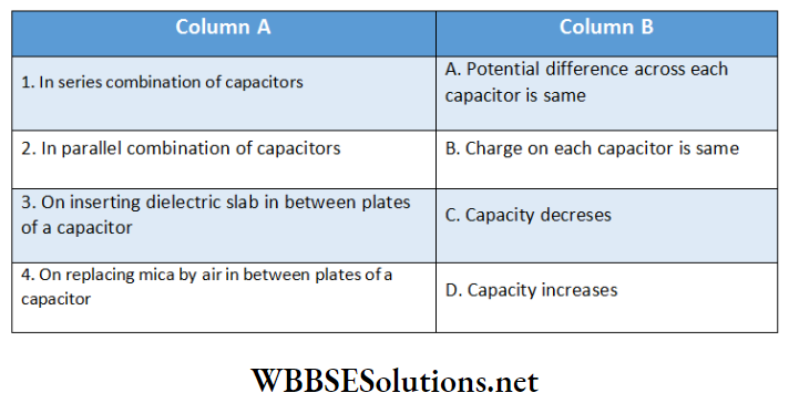
Answer: 1-B,C 2-A,D 3-D, 4-C
Question 5. In the area of each plate is A. Match the following.
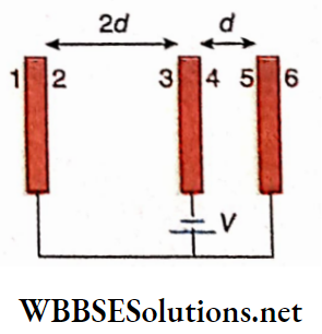
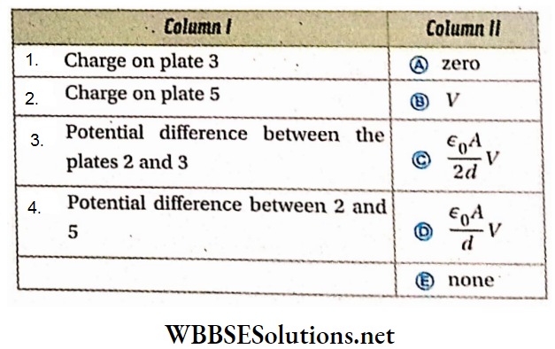
Answer: 1-E, 2-D, 3-B, 4-A