WBCHSE Class 12 Physics Lens Notes
Refraction Of Light At Spherical Surface Lens Introduction
We have discussed in the previous chapter the refraction of light at a plane surface separating two transparent media and the formation of Image due to It. If the surface of separation be spherical (concave and convex), how light will be refracted and how the image will be formed will be discussed in the present chapter. The refraction of light in a lens and its principle of action can easily be understood from the refraction oflight at a spherical surface.
Refraction Of Light At Spherical Surface Lens Spherical Refracting Surfaces
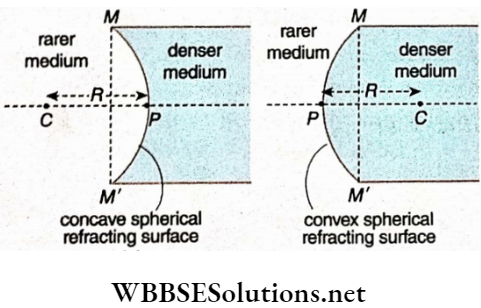
A spherical refracting surface is the part of a sphere separating two transparent media
The spherical refracting surfaces are of two types :
- Concave spherical refracting surface which is concave towards the rarer medium
- Convex spherical refracting surface which is convex towards the rarer medium
WBBSE Class 12 Refraction at Spherical Surfaces Notes
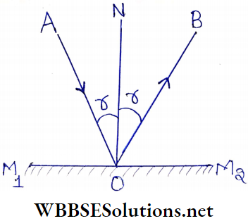
Refraction Of Light At Spherical Surface Lens A Few Terms Related To Spherical Refracting Surfaces
Pole: The midpoint P of the spherical refracting surface called the pole of the surface
Centre of curvature: The centre of the sphere C, of which the curved refracting surface forms a part is called the centre of curvature of the surface.
Read and Learn More Class 12 Physics Notes
The radius of curvature: The radius of the sphere of which the refracting surface is a part is called the radius of curvature of the surface. PC is the radius of curvature (R) of each surface. It is equal to the distance of the centre of curvature from the pole of the surface.
Principal axis: The straight line joining the pole and the centre of curvature of the spherical refracting surface is called the principal axis of the surface. In the line PC extended both ways is the principal axis.
Aperture: The effective diameter of the refracting spheri¬ cal surface exposed to the incident light is called the aperture of the surface. In the line joining M end M’ i.e., the line MM’ is the aperture of the spherical refracting surface.
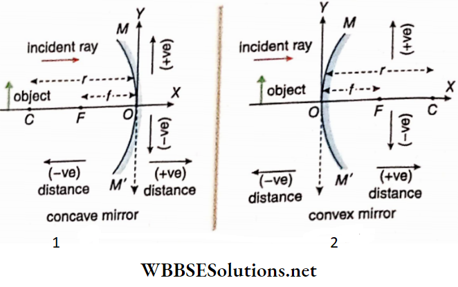
Refraction Of Light At Spherical Surface Lens Sign Convention
- All distances are measured from the pole of the spherical surface.
- The distances measured from the pole in the direction opposite to the direction of the incident ray are taken as negative and those measured in the direction of the incident ray are taken as positive
- If the principal axis of the spherical refracting surface is taken as x -the x-axis, distances along the y – y-axis above the principal axis are taken as positive and distances along y -axis below the principal axis are taken as negative.
Assumptions
While studying refraction through spherical surfaces following assumptions are made:
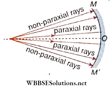
- The aperture of the spherical refracting surface is small.
- Refraction of only paraxial rays will be considered
The object will be a point object and will lie on the principal axis.
Refraction Of Light At Spherical Surface Lens Refraction At Spherical Surfaces
Refraction at Concave Surface
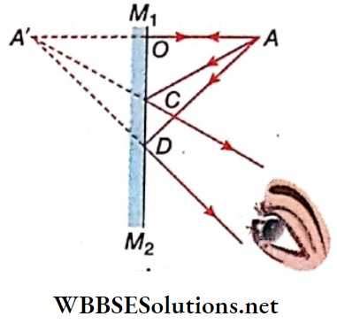
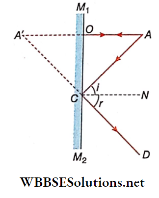
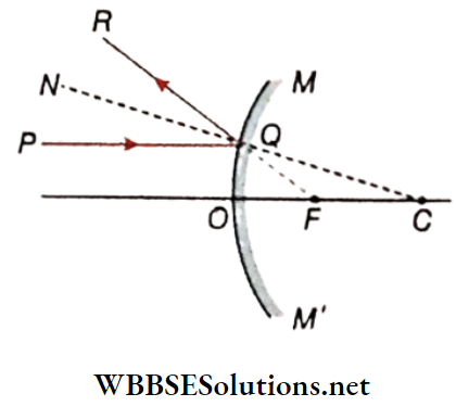
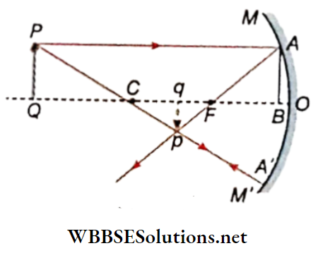
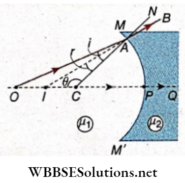
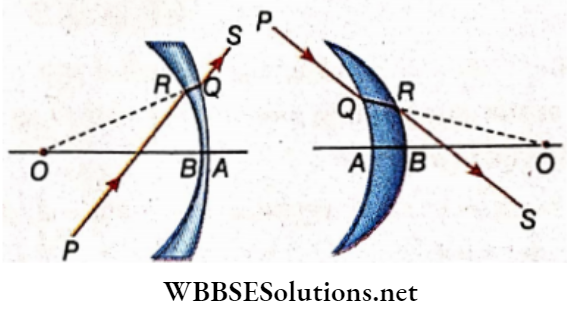
1. When the object is real and lies in a rarer medium and the image formed is virtual:
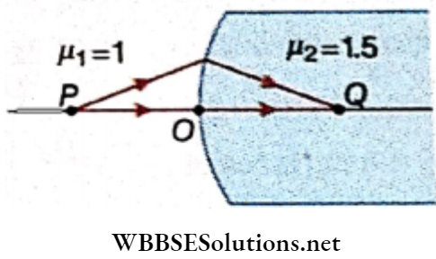
Let MPM’ be a concave surface separating two media of refractive indices μ1 and μ2 ( μ1 >μ2) . Let P be the pole and C be the centre of curvature of the concave surface. A point object O is placed in the rarer medium on the principal axis OP.
An incident ray OA, after refraction at point A on the surface bends towards the normal CAN and goes along AB in the denser medium. Another ray OP moving along the principal axis is incident on the surface normally and hence gets undeviated into the denser medium. The two refracted rays AB and PQ being divergent meet at / when produced backwards. I is the virtual image of O.
Let angle of incidence, ∠OAC – i; angle of refraction, ∠BAN = opposite angle ∠IAC = r; ∠ACO = θ; object distance, PO = -u; image distance, PI = -v; radius of curvature, PC = -R
Now from the triangle AOC have
⇒ \(\frac{\sin i}{C O}=\frac{\sin \theta}{A O} \text { or, } \frac{\sin i}{\sin \theta}=\frac{C O}{A O}\)
From the triangle AIC we have
⇒ \(\frac{\sin r}{C I}=\frac{\sin \theta}{A I}, \text { or, } \frac{\sin r}{\sin \theta}=\frac{C I}{A I}\)
Again considering refraction at point A, according to Snell’s law we have
μ1 sin i = μ2 sin
Or, \(\mu_1 \frac{\sin t}{\sin \theta}=\mu_2 \frac{\sin r}{\sin \theta}\)…………. (3)
From equations (1), 2) and(3) we have,
For the small aperture of the spherical surface
AO ≈ PO; and AI ≈ PI
Or, \(\mu_1\left(\frac{P O-P C}{P O}\right)=\mu_2\left(\frac{P I-P C}{P I}\right)\)
Or, \(\mu_1\left(1-\frac{P C}{P O}\right)=\mu_2\left(1-\frac{P C}{P I}\right)\)
Or, \(\mu_1\left(1-\frac{-R}{-u}\right)=\mu_2\left(1-\frac{-R}{-v}\right)\)
Or, \(\mu_1\left(1-\frac{R}{u}\right)=\mu_2\left(1-\frac{R}{v}\right) \text { or, }\left(\frac{\mu_2}{v}-\frac{\mu_1}{u}\right) R=\mu_2-\mu_1\)
Or, \(\frac{\mu_2}{v}-\frac{\mu_1}{u}=\frac{\mu_2-\mu_1}{R}\) …………….. (4)
Equation (4) is called Gauss’ equation for refraction at a concave spherical surface.
If the object O is in air, μ1 = 1 and μ2 = μ (say), then equation (4) becomes
⇒ \(\frac{\mu}{v}-\frac{1}{u}=\frac{\mu-1}{R}\)…………………….. (5)
Short Notes on Spherical Lenses and Refraction
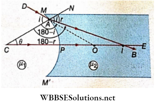
2. When the object is virtual and the Image formed is real:
Let MPM’ be a concave surface separating two media of refracting indices μ1 and μ2 ( μ2 > μ1 ) the pole and C be the centre of curvature of the concave surface.
O is the virtual point object on the principal axis of the concave surface and I is its real image.
Let angle of incidence ∠DAC = opposite angle ∠NAO = i; angle of refraction, ∠NAI = r; ∠ACP = Q ; virtual object distance, PO = u; real image distance, PI = v; radius of curvature,
Now, from ΔAOC we have
⇒ \(\frac{\sin \left(180^{\circ}-i\right)}{C O}=\frac{\sin \theta}{A O}\)
Or, \(\frac{\sin i}{C O}=\frac{\sin \theta}{A O}\)
Or, \(\frac{\sin i}{\sin \theta}=\frac{C O}{A O}\) ……………………… (6)
From ΔACI we have,
⇒ \(\frac{\sin \left(180^{\circ}-r\right)}{C I}=\frac{\sin \theta}{A I}\)
Or, \(\frac{\sin r}{\sin \theta}=\frac{C I}{A I}\) ……………………… (7)
Again considering refraction at point A, according to Snell’s law we have,
⇒ \(\mu_1 \sin i=\mu_2 \sin r\)
Or, \(\mu_1 \cdot \frac{\sin i}{\sin \theta}=\mu_2 \cdot \frac{\sin r}{\sin \theta}\) ……………………… (8)
From equations (6), (7) and (8) we have
⇒ \(\mu_1 \cdot \frac{C O}{A O}=\mu_2 \cdot \frac{C I}{A I}\)
Or, \(\mu_1 \frac{C O}{P O}=\mu_2 \frac{C I}{P I}\) [ Small aperture approximation]
Or, \(\mu_1\left(\frac{C P+P O}{P O}\right)=\mu_2\left(\frac{C P+P I}{P I}\right)\)
Or, \(\mu_1\left(1+\frac{C P}{P O}\right)=\mu_2\left(1+\frac{C P}{P I}\right)\)
Or, \(\mu_1\left(1+\frac{-R}{u}\right)=\mu_2\left(1+\frac{-R}{v}\right)\)
Or, \(\mu_1\left(1-\frac{R}{w}\right)=\mu_2\left(1=\frac{R}{v}\right)\)
Or, \(\left(\frac{\mu_2}{v}-\frac{\mu_1}{u}\right) R=\mu_2-\mu_1\)
Or, \(\frac{\mu_2}{v}-\frac{\mu_1}{u}=\frac{\mu_2-\mu_1}{R}\) …………………………….. (9)
If μ1 = 1 and μ2= 2 equation (9) takes the form
⇒ \(\frac{\mu}{v}-\frac{1}{u}=\frac{\mu-1}{R}\)…………….. (10)
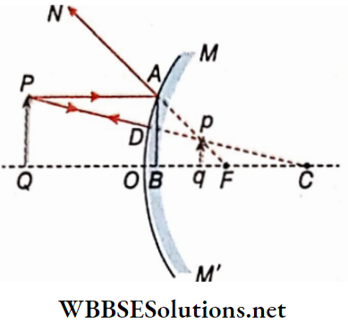
When the object is real and lies in a denser medium and the image formed is virtual:
In MPM’ is a spherical surface which is concave towards the rarer medium.
Object O is placed in the denser medium. The virtual image of the object is I.
Here μ1 >μ2
Let angle of incidence, ∠DAO = i;
Angle of refraction, ∠BAC = r; ∠ACP = θ
Object distance, PO = -u;
Image distance, PI = -v;
The radius of curvature, PC = R
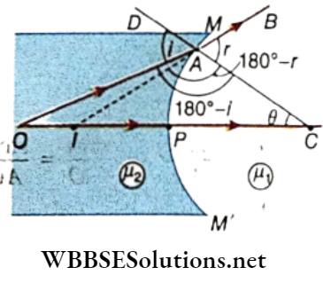
Now, from the triangle ACO, we have,
⇒ \(\frac{\sin \left(180^{\circ}-i\right)}{O C}=\frac{\sin \theta}{O A}\)
Or, \(\frac{\sin i}{O C}=\frac{\sin \theta}{O A}\) ……………….. (11)
And we have from AACI
⇒ \(\frac{\sin \left(180^{\circ}-r\right)}{I C}=\frac{\sin \theta}{I A}\)
Or, \(\frac{\sin r}{\sin \theta}=\frac{I C}{I A}\) …………… (12)
Again considering refraction at point A, according to Snell’s law we have,
μ1 sin i = μ2 sin r
⇒ \(\mu_2 \frac{\sin i}{\sin \theta}=\mu_1 \frac{\sin r}{\sin \theta}\)
From the equations (11), (12) and (13) we have
⇒ \(\mu_2 \cdot \frac{O C}{O A}=\mu_1 \cdot \frac{I C}{I A}\)
Or, \(\mu_2\left(\frac{O P+P C}{O P}\right)=\mu_1\left(\frac{I P+P C}{I P}\right)\)
∴ For small aperture of the spherical surface OA≈OP; IA≈IP
Or, \(\mu_2\left(1+\frac{P C}{O P}\right)=\mu_1\left(1+\frac{P C}{I P}\right)\)
Or, \(\mu_2\left(1+\frac{R}{-w}\right)=\mu_1\left(1+\frac{R}{-v}\right) \text { or, } \mu_2\left(1-\frac{R}{w}\right)=\mu_1\left(1-\frac{R}{v}\right)\)
Or, \(\mu_2-\mu_1=\mu_2 \cdot \frac{R}{u}-\mu_1 \cdot \frac{R}{v}\)
Or, \(\mu_2-\mu_1=R\left(\frac{\mu_2}{u}-\frac{\mu_1}{v}\right) \text { or, } \frac{\mu_2}{u}-\frac{\mu_1}{v}=\frac{\mu_2-\mu_1}{R}\)
Or, \(\frac{\mu_1}{v}-\frac{\mu_2}{u}=\frac{\mu_1-\mu_2}{R}\) ……………………. (14)
If μ2 = μ and μ1 = 1, the equation (14) takes the form
⇒ \(\frac{1}{v}-\frac{\mu}{u}=\frac{1-\mu}{R}\)
Or, \(\frac{\mu}{u}-\frac{1}{v}=\frac{\mu-1}{R}\)…………………. (15)
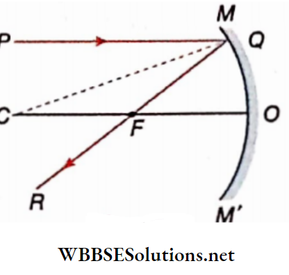
Refraction at Convex Surface
1. When the object is real and lies in a rarer medium and the image formed is virtual:
Let MPM’ be a convex surface separating two media of refractive indices and μ2 (μ2>μ1)
An incident ray of OA after refraction at point A on the surface goes along AB in the denser medium
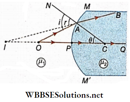
Another ray of tight OP moving along the principal axis Is incident on the surface normally and hence gets undeviated into the denser medium. The two refracted rays AB and PQ when produced back meet on the principle axis at point I which is the virtual image Of O
Let the angle of incidence ∠OAN = r
∴ ∠CAO = 180°- i
Angle of refraction, ∠BAC = ∠IAN = r
∴ ∠CAI = 180°-r
Let, ∠ACO = θ
Object distance a PO = -u
Image distance, PI = -v
radius of curvature, PC = R
From tire ΔACO we have
⇒ \(\frac{\sin \left(180^{\circ}-i\right)}{C O}=\frac{\sin \theta}{A O}\)
Or, \(\frac{\sin i}{C O}=\frac{\sin \theta}{A O}\)
Or, \(\frac{\sin i}{\sin \theta}=\frac{C O}{A O}\)
From the ΔACI we have
⇒ \(\frac{\sin \left(180^{\circ}-r\right)}{C I}=\frac{\sin \theta}{A I}\)
Or, \(\frac{\sin r}{C I}=\frac{\sin \theta}{A I}\)
Or, \(\frac{\sin r}{\sin \theta}=\frac{C l}{A l}\)
Again, considering ing refraction at point A, according to Snell’s law we have
μ1 sin = μ2 sin r
⇒ \(\mu_1 \cdot \frac{\sin i}{\sin \theta}=\mu_2 \cdot \frac{\sin r}{\sin \theta}\). ………………………………. (3)
From equations (1), (2) and (3) we have
⇒ \(\mu_1 \cdot \frac{C O}{A O}=\mu_2 \cdot \frac{C I}{A I}\)
⇒ \(\mu_1 \cdot \frac{C O}{A O}=\mu_2 \cdot \frac{C I}{A I}\)
∴ For small aperture of the spherical surface AO ≈ PO, AI≈pI
⇒ \(\mu_1\left(\frac{P C+P O}{P O}\right)=\mu_2\left(\frac{P C+P I}{P I}\right)\)
⇒ \(\mu_1\left(\frac{P C}{P O}+1\right)=\mu_2\left(\frac{P C}{P I}+1\right)\)
⇒ \(\mu_1\left(\frac{P C}{P O}+1\right)=\mu_2\left(\frac{P C}{P I}+1\right)\)
Or, \(\mu_1\left(\frac{R}{-u}+1\right)=\mu_2\left(\frac{R}{-\nu}+1\right)\)
⇒ \(\mu_1\left(1-\frac{R}{u}\right)=\mu_2\left(1-\frac{R}{\nu}\right) \text { or, }\left(\frac{\mu_2}{\nu}\right)\)
Or, \(\frac{\mu_2}{\nu}-\frac{\mu_1}{u}=\frac{\mu_2-\mu_1}{R}\) …………………….(4)
Equation (4) is called Gauss’ equation for refraction for refraction at a convex spherical surface.It is similar to the equation (4)
If object O Is situated In the air, μ1 = 1 and μ2 = μ (say)
Convex spherical surface. It Is similar to the equation (4) of the equation (4) becomes
⇒ \(\frac{\mu}{\nu}-\frac{1}{u}=\frac{\mu-1}{R}\) ……………………… (5)
2. When the object is real and lies In a rarer medium and the Image formed Is also real:
Let MPM’ be a convex surface separating two media of refractive Indices μ1 and μ2 ( μ2 > μ1 ). Let P be the pole and C be the centre of curvature of the convex surface. O is the point object on the principal axis of the convex surface and I is its real Image.
Let the angle of Incidence, ∠NAO = i
The angle of refraction,∠ IAC = r;
∠ACO = θ
Object distance, PO = -u
Image distance, PI = v
The radius of curvature, PC = R
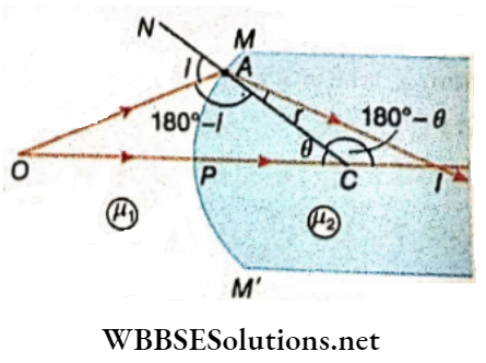
Now, from ΔACO we have
⇒ \(\frac{\sin \left(180^{\circ}-i\right)}{C O}=\frac{\sin \theta}{A O}\)
Or, \(\frac{\sin i}{C O}=\frac{\sin \theta}{A O}\)
Or, \(\frac{\sin l}{\sin \theta}=\frac{C O}{A C}\) …………………………………….. (6)
From ΔAIC we have
⇒ \(\frac{\sin r}{C I}=\frac{\sin \left(180^{\circ}-\theta\right)}{A I}\)
Or, \(\frac{\sin r}{\sin \theta}=\frac{C I}{A I}\) ……………………………………….. (7)
Again, considering refraction at point A, according to Snell’s law we have,
μ1 Sini = μ2 Sini r
Or, \(\mu_1 \cdot \frac{\sin i}{\sin \theta}=\mu_2 \cdot \frac{\sin r}{\sin \theta}\) ………………………………. (8)
From equations (6), (7) and (8) we have,
⇒ \(\mu_1 \cdot \frac{C O}{A O}=\mu_2 \cdot \frac{C I}{A I}\)
Or, \(\mu_1 \cdot \frac{C O}{P O}=\mu_2 \cdot \frac{C I}{P I}\)
For the small aperture of the spherical surface AO ≈ PO, AI ≈ PI
Or, \(\mu_1\left(\frac{P O+P C}{P O}\right)=\mu_2\left(\frac{P I-P C}{P I}\right)\)
Or, \(\mu_1\left(1+\frac{P C}{P O}\right)=\mu_2\left(1-\frac{P C}{P I}\right)\)
Or, \(\mu_1\left(1+\frac{R}{-u}\right)=\mu_2\left(1-\frac{R}{v}\right)\)
Or, \(\mu_1\left(1-\frac{R}{w}\right)=\mu_2\left(1-\frac{R}{v}\right)\)
Or, \(\frac{\mu_2}{v}-\frac{\mu_1}{u}=\frac{\mu_2-\mu_1}{R}\) ………………………………………. (9)
If the object O is situated in air, μ1 = 1 and μ2 = μ (say) the equation (9) becomes
Or, \(\frac{\mu}{v}-\frac{1}{u}=\frac{\mu-1}{R}\)……………………………………….. (10)
WBCHSE class 12 physics lens notes
2. When the object is real and lies in a denser medium and the image formed is real:
In MPM’ is a spherical surface which is convex towards the rarer medium. The object O is placed in the denser medium. The real image formed is I.
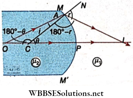
Let the angle of incidence, ∠CAO = i
The angle of refraction, ∠NAI = r;
∠ACP = θ;
Object distance, PO = -u
Image distance, PI = + v
The radius of curvature, PC = -R
Now, from the triangle ACO we have
⇒ \(\frac{\sin i}{O C}=\frac{\sin (180-\theta)}{O A}\)
Or, \(\frac{\sin i}{O C}=\frac{\sin \theta}{O A}\)
Or, \(\frac{\sin i}{\sin \theta}=\frac{O C}{O A}\)…………………………………… (11)
From the triangle AIC, We have,
⇒ \(\frac{\sin \left(180^{\circ}-r\right)}{C I}=\frac{\sin \theta}{A I}\)
Or, \(\frac{\sin r}{\sin \theta}=\frac{C I}{A I}\) ………………………… (12)
Again considering refraction at point A, according to Snell’s law we have,
μ1 sini = μ2 sin r
Or, \(\mu_2 \cdot \frac{\sin i}{\sin \theta}=\mu_1 \cdot \frac{\sin r}{\sin \theta}\) ……………………………. (13)
From equations (11), (12) and (13) we have,
⇒ \(\mu_2 \cdot \frac{O C}{O A}=\mu_1 \cdot \frac{C I}{A I}\)
Or, \(\mu_2 \cdot \frac{O C}{O P}=\mu_1 \cdot \frac{C I}{P I}\)
For small aperture of the spherical surface OA ≈ OP; IA ≈ IP
Or, \(\mu_2\left(\frac{O P-P C}{O P}\right)=\mu_1\left(\frac{P I+P C}{P I}\right)\)
Or, \(\mu_2\left(1-\frac{P C}{O P}\right)=\mu_1\left(1+\frac{P C}{P I}\right)\)
Or, \(\mu_2\left(1-\frac{-R}{-w}\right)=\mu_1\left(1+\frac{-R}{v}\right)\)
Or, \(\left(\frac{\mu_1}{v}-\frac{\mu_2}{u}\right) R=\mu_1-\mu_2\)
Or, \(\frac{\mu_1}{v}-\frac{\mu_2}{u}=\frac{\mu_1-\mu_2}{R}\) ……………………. (14)
If μ2 = μ and μ1= 1 the equation (14) takes the form
⇒ \(\frac{1}{v}-\frac{\mu}{u}=\frac{1-\mu}{R}\)
Or, \(\frac{\mu}{u}-\frac{1}{v}=\frac{\mu-1}{R}\) ………………………………………. (15)
If the object is a mat and lies In a rarer medium, then relation \(\frac{\mu_2}{v}-\frac{\mu_1}{u}=\frac{\mu_2-\mu_1}{R}\) is valid irrespective of the type of the spherical refracting surface
If the object is real and lies in the denser medium, then relation \(\frac{\mu_1}{v}-\frac{\mu_2}{u}=\frac{\mu_1-\mu_2}{R}\) is valid irrespective of the type of the spherical refracting surface
Here u = object distance, v = image distance, r = radius of Air Venture of spherical refracting surface, μ1 = refractive index of rarer medium and μ2 = refractive index of denser medium
Refraction At Spherical Surfaces Class 12 Notes
Refraction Of Light At Spherical Surface Lens Refraction At Spherical Surfaces Numerical Examples
Example 1. There is a small air bubble inside a glass sphere; (μ = 1.5) of radius 10 cm. The bubble is 4 cm below the surface and is viewed nearly normal from the out side. Find the apparent depth of the bubble
Solution:
Here, u = -4 cm; r = -10 cm; μ2 = 1.5, μ1= 1
O is the position of the bubble and I is the position of the image of the bubble
We know, \(\frac{\mu_1}{v}-\frac{\mu_2}{u}=\frac{\mu_1-\mu_2}{r}\)
Or, \(\frac{1}{v}-\frac{1.5}{-4}=\frac{1-1.5}{-10}\)
Or, \(\frac{1}{v}=\frac{0.5}{10}-\frac{1.5}{4}\)
Or, v = -3 cm
Thus the bubble will appear 3 cm below the top point of the sphere.
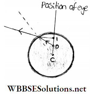
Example 2. A point of red mark on the surface of a glass sphere Is observed straight, nearly along the diameter from the opposite surface of the sphere. If the diameter of the sphere is 20 cm and the refractive index of the glass is 1.5, find the position of the image. Sftlutlan: Let P be a point of red mark on the glass sphere being observed from point A
Solution:
According to the question, object distance = AP = u = -20: radius of curvature = r = -10 cm
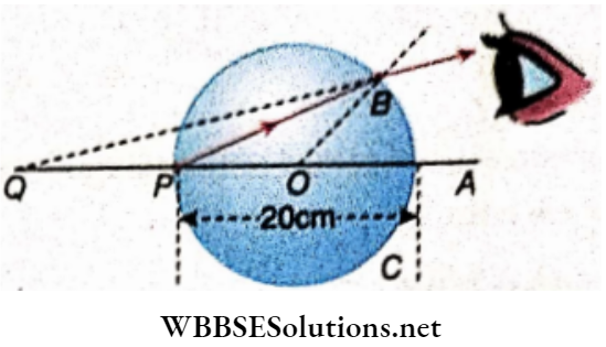
In this case, the object lies in the denser medium μ2= 1.5
The observer is situated in the rarer medium (μ1= 1)
So, in case of refraction in the spherical surface BAC
⇒ \(\frac{\mu_1}{v}-\frac{\mu_2}{u}=\frac{\mu_1-\mu_2}{r}\)
Or, \(\frac{1}{v}-\frac{1.5}{-20}=\frac{1-1.5}{-10}\)
Or, \(\frac{1}{v}+\frac{15}{200}=\frac{-0.5}{-10}\)
Or, \(\frac{1}{v}=\frac{5}{100}-\frac{15}{200}\)
Or, \(\frac{1}{v}=\frac{10-15}{200}=\frac{-5}{200}\)
or, v = -40 cm
So, a virtual image will be formed on Q on the extended line AOP at a distance of 40 cm from point A. So the virtual position of the red spot will be found (40- 20) or 20 cm behind its real position while looking through the sphere
Common Questions on Refraction at Lenses
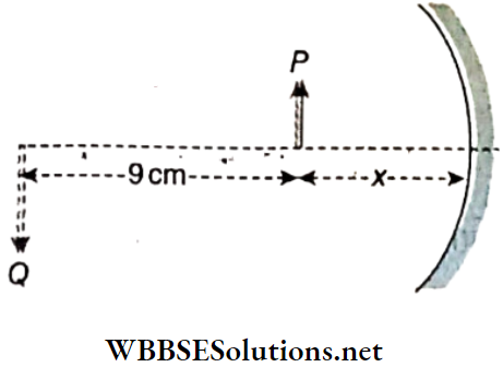
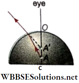
Example 3. A mark exists at a distance of 3 cm on the axis from the plane surface of a hemisphere of glass. If the mark Is observed from above the curved surface determine the apparent position of the mark. The radius of the hemisphere = 10 cm; the refractive index of glass = 1.5.
Solution:
A is the position of the mark A’ is the position of its image.
u = -OA = -(OC- AC) = -(10 – 3) = -7 cm
r = -10 cm; μ2 = 1.5 and μ1= 1
We know \(\frac{\mu_1}{v}-\frac{\mu_2}{u}=\frac{\mu_1-\mu_2}{r}\)
Or, \(\frac{1}{v}-\frac{1.5}{-7}=\frac{1-1.5}{-10}\)
Or, \(\frac{1}{v}+\frac{1.5}{7}=\frac{0.5}{10}\)
Or, \(\frac{1}{v}=\frac{0.5}{10}-\frac{1.5}{7}\)
Or, \(\frac{1}{v}=\frac{-11.5}{70}\)
Or, v = – 6.09 cm
∴ Position of±e ima8e from the plane surface is at a distance of (10 – 6.09) or 3.91 cm
Example 4. A parallel beam of light travelling In the water is refracted a by a spherical air bubble of radius 2 mm situated In the water. Find the position of the Image due to refraction at the first surface and the position of the final Image. Refractive Index of water = 1.33. Draw a ray diagram showing the positions of both the Images.
Solution:
Let C be the centre of the spherical air bubble. P1 and P2 are the poles of the spherical surfaces. A beam of light parallel to the diameter of the sphere, after refraction at the first surface, forms a virtual Image I1 After that it forms another virtual image I2 due to refraction at the second surface.
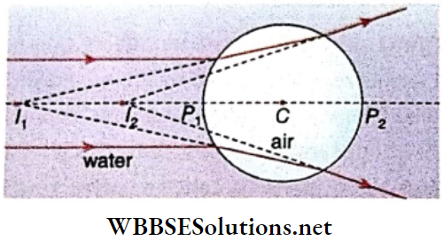
We know \(\frac{\mu_1}{v}-\frac{\mu_2}{u}=\frac{\mu_1-\mu_2}{r}\)
For refraction at the first surface of the bubble (from water to air)
μ1 = 1 ,μ2 = 1.33 ; u = ∞ and r = 2 mm
⇒ \(\frac{1}{v}=\frac{1.33}{\infty}=\frac{1-1.33}{2}\)
Or, \(\frac{1}{v}=\frac{-1}{6}\)
v = -6 mm
The negative sign indicates that the image Ix is virtual and forms at 6 mm from the surface of the bubble on the waterside. The refracted rays (which seem to come from I1 ) are incident on the farther surface of the bubble. For this refraction, μ1 = 1, μ2 = 1. 33 , r = 2 mm and u = -(6 + 4) = -10 mm
∴ \(\frac{\mu_2}{v}-\frac{\mu_1}{u}=\frac{\mu_2-\mu_1}{r}\)
Or, \(\frac{1.33}{\nu}+\frac{1}{10}=\frac{1.33-1}{-2}\)
Or, \(\frac{1.33}{v}=\frac{-0.33}{2}-\frac{1}{10}\)
Or, v = – 5mm
The negative sign shows that the image is formed on the air side at 5 mm from the second refracting surface.
Measuring from the centre of the bubble the first image is formed at (6+2) or 8 mm from the centre and the second image is formed at (5- 2). or 3 mm from the centre. Both images are formed on the side from which the incident rays are coming.
Practice Problems on Lens and Spherical Surface Refraction
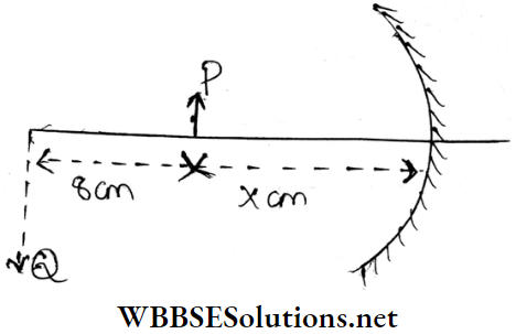
Example 5. A spherical surface of radius of curvature R separates air (refractive Index 1.0) from glass (refractive Index = 1.5). The centre of curvature Is In the glass A point object P placed In the air is found to have a real Image Q In the glass. The line PQ cut the surface at a point O and PO = OQ. Find the distance of the object from the spherical surface.
Solution:
Let PO = OQ = x. Suppose object and image distances are u and v respectively.
We, know ,\(\frac{\mu_2}{v}-\frac{\mu_1}{u}=\frac{\mu_2-\mu_1}{R}\)
Here, μ2 = 1.5 , μ1 = 1, v = +x, u = -x
From equation (1),
⇒ \(\frac{1.5}{x}-\frac{1}{-x}=\frac{1.5-1}{+R}\)
Or, \(\frac{2.5}{x}=\frac{0.5}{R}\)
Or, x = 5R
Hence distance of the object from the spherical surface is 5R.
Refraction Of Light At Spherical Surface Lens Application Of Refraction In A Spherical Surface Lens
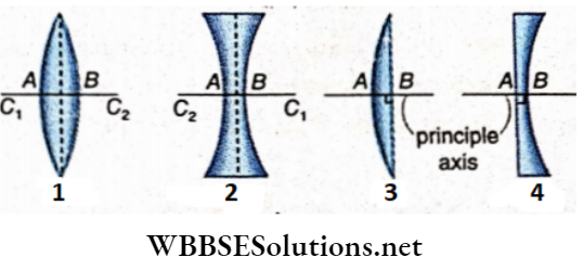
Spherical surface Definition: A lens Is a portion of a transparent refracting medium bounded by two spherical surfaces or a spherical surface and a plane surface.
The lens is generally of two types:
- Convex or converging lens and
- Concave or diverging lens.
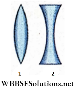
A lens which is thicker in the middle than towards its edges is called a convex lens. A lens which is thinner in the middle than towards the edges is called a concave lens
Refraction at spherical surfaces class 12 notes
Refraction Of Light At Spherical Surface Lens Different Types Of Lenses
Convex lens
Convex lenses may be of three types according to the shape of two surfaces forming it.
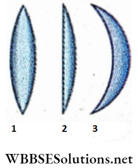
- Bi-convex or double convex lens: It is one in which both the surfaces are convex The radii of curvature of both the surfaces may or may not be equal. If the radii of curvature are equal, the convex lens is called the equi-convex lens.
- Plano-convex lens: It is a lens with one surface plane and the other convex.
- Concavo-convex lens: Here one surface is concave and the other is convex In this type of lens the radius of curvature of the convex surface is smaller than that of the concave surface.
Concave lens
Similarly, the concave lens may be of three types according to the shape of two surfaces forming it
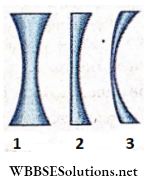
- Bi-concave or double-concave Lens: This type of lens has both surfaces concave. The radii of curvature of both surfaces may or may not be equal. If the radii of curvature are equal, the. concave lens is called the equiconcave lens.
- Plano-concave lens: This type of lens has one surface, plane and the other concave.
- Convexo-concave lens: Here one surface Is convex and the other is concave. The radius of curvature of the concave surface Is smaller than that of the convex surface,
Refraction at spherical surfaces class 12 notes
Refraction Of Light At Spherical Surface Lens Action Of A Lens
Principal axis
The line passing through the centres of curvature of the two bounding surfaces of a lens Is called the principal axis of the lens. If one surface of the lens is spherical and the other plane, then the perpendicular drawn from the curvature of the spherical surface to the plane surface is the principal axis of the lens. [The definition of centre of curvature is given in the section 3.9
Converging and diverging lenses
If the surrounding medium of a lens is rarer compared to the medium of the lens, then the parallel beam of rays after refraction through a convex or a concave lens appears to be converging or diverging respectively. Therefore, a convex lens is called a converging lens and a concave lens is called a diverging lens.
1. Convergence by the convex lens:
A convex lens may be imagined as being formed of two sets of truncated prisms arranged symmetrically on the opposite sides of a central paral¬ lel-faced rectangular slab. the prisms in each set being placed one above another with their bases turned towards the principal axis of the lens
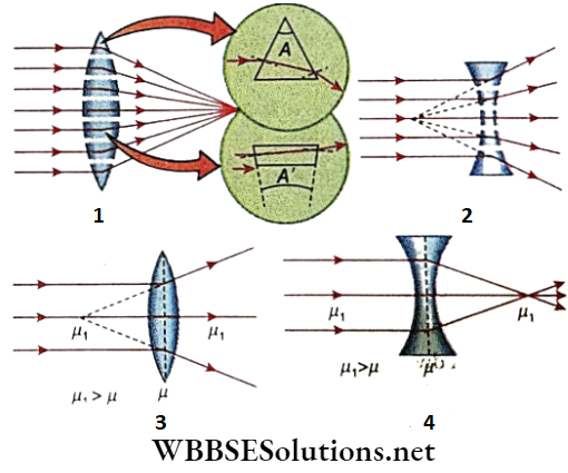
As we move further away from the principal axis the angle of refraction consequently keeps on increasing. Any parallel ray incident on a prism will bend by refractippÿthrough the prism towards its base. Since the refracting angles of.the various prisms.
Increase successively with their distance from the principal axis, the raj’s which fall on a prism at a distance from the axis is bent more than those which pass nearer to the axis. So a pencil of parallel rays is refracted by the combination of prisms i.e, by the convex lens to converge to a particular point on the princi¬ pal axis. Hence, a convex lens is called a converging lens,
2. Divergence by concave lens:
Let us refer to the concave lens may also be imagined as being formed of two sets of truncated prisms arranged symmetrically on the opposite sides of a central parallel-faced slab. The pile of prisms on each side of the principal axis have their refracting angles turned towards the axis. So their bases are turned towards the edge of the lens.
Therefore in this case a pencil of parallel rays after refraction through the prism will bend away from the axis being tinned towards foe bases of foe prisms. So for emergent light will behave as a divergent beam. Hence, a concave lens is called a diverging lens.
Divergence by the convex lens and convergence by the concave lens
It is to be noted that usually, a convex lens acts as a converging lens and a concave lens as a diverging one. These types of behaviour offoe lenses are seen when foe refractive indices offoe material of foe lenses are greater than that of the surrounding medium. But if the refractive index of the material of for lens is less than that of the surrounding medium i.e., the medium surrounding the lens is denser, the convex lens will diverge and a concave lens will converge for incoming parallel rays
Refraction at spherical surfaces class 12 notes
Refraction Of Light At Spherical Surface Lens A Few Definitions
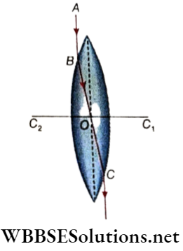
Centre of curvature: Generally the two surfaces of a lens are spherical. The two spherical surfaces are each a part of two spheres. The centres of the spheres are called the centres of curvature of the Idris.
If for two surfaces of a lens are spherical, the centres of the nature of the lens are at a finite distance. C1 and C2 are the centres of curvature of the lenses. If the surface of the lens is plane, the centre of curvature of that surface is at infinity
Radius Of curvature
The two spherical surfaces are each a part of two spheres. The radii of the spheres are called the radii of curvature of the lens.
If the two surfaces of a lens are spherical, each radius of curvature is finite. AC2 and BC1 are the radii of curvature of the lens. If one of the surfaces is plane, its radius of curvature is infinite
Principal axis
For a lens having two spherical surfaces, the line passing through the centres of curvatures of the two bounding surfaces of a lens is called the principal axis of the lens for the principal axis of the ~ lens.
If one surface of the lens is spherical and the other is a plane, then the perpendicular drawn from the centre of curvature of the spherical surface to the plane surface is the principal axis of the lens
Optical centre
If a ray of light passes through a lens in such a way that the direction of emergence is parallel to the direction of incidence, the path of the ray inside the lens intersects the principal axis at a fixed point. This fixed point for a lens is called its optical centre
The incident ray AB and the emergent ray CD are parallel to each other. The refracted ray BC intersects the principal axis at O . So point 0 is the optical centre of the lens.
It is to be noted that the incident ray AB and the emergent CD do not lie on the same straight line. The emergent ray CL is laterally displaced from the incident ray AB. The displacement will be small if the lens is a thin one. If the lens is very thin
The displacement is so negligible that AB, BC and CD may be taken as the same straight line. So we can say that the optical centre of a thin lens Is such n point on Its principal axis that a ray passing through it passes out straight without any displacement or deviation.
The optical centre is a fixed point:
The optical centre of a lens Is a fixed point on Its principal axis. But the position of the point depends oil its shape. It can be proved in die following way.
C1 and C2 are the centres of curvature of the spherical surfaces LBL’ and LAL’ respectively. Q and R are two points on the spherical surfaces. If r1 and r2 are the radii of curvature of the surfaces LBL’ and LAL’ then C1Q = C1B = r1 and C2R = C2A = r1
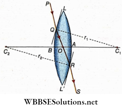
Let us join Q and R and let the line QR intersect the principal axis at O . Therefore, O is the optical centre of the lens. Thus the rays PQ and RS are parallel to each other. Suppose, the thickness of the lens =AB = t.
Two tangent planes are drawn at Q and R of the two surfaces of the lens. We know that when a ray is refracted through a parallel glass slab the incident ray and the emergent ray are parallel.
In this case, the rays PQ and RS being parallel we can assume that the ray PQ is refracted through a parallel glass slab. So the tan¬ gent planes at Q and R will be parallel to each other.
The radius of curvature C1Q is perpendicular to the tangent plane at Q and the radius of curvature C2R is perpendicular to the tangent plane at R. Since the two tangent planes are parallel, therefore C1Q and C2 R are parallel, to each other.
So the triangles C1OQ and C2OR are similar.
∴ \(\frac{O C_1}{O C_2}=\frac{C_1 Q}{C_2 R}=\frac{r_1}{r_2}\)
∴ \(\frac{O C_1}{O C_2}=\frac{C_1 n}{C_2 A}\)
= \(\frac{C_1 B-O C_1}{C_2 A-O C_2}=\frac{O B}{O A}\)
⇒ \(\frac{r_1}{r_3}=\frac{O B}{O A}\)
So, the point O divides the thickness of the lens AB In a fixed ratio i.e., in ratio of the radii of curvature of the two surfaces
Again \(\frac{r_1}{r_1+r_2}=\frac{O B}{O B+O A}=\frac{O B}{A B}=\frac{O B}{t}\)
∴ OB = \(\frac{t r_1}{r_1+r_2}\), OA = \(\frac{t r_2}{r_1+r_2}\) …………………………………………. (2)
Since t, r1 and r2 are constants, the position of O is constant. i.e., the optical centre O of a lens is a fixed point.
- In the case of equi-convex and equi-concave lenses: In this case since r1 = r2 therefore from equation (1), we get OB = OA. i.e., in this case, the optical centre is situated on the principal axis within the lens and equidistant from both surfaces.
- In the case of plano-convex and plano-concave lenses: In this case, one surface of the lens is the plane. Therefore when r1→∞ , then OA →0. Again when r2→ ∞ , then OB →0. So, in this case, the optical centre lies at the intersecting point of the spherical surface with the principal axis
It is to be noted that the optical centre may be within the lem or outside, depending on the nature of the two surfaces, the case of the concavo-convex and convexo-concave optic centre lies outside the lens, Wherever the position of the optical centre, its distance from any surface of lens is proportional to the radius of curvature of the surface because
⇒ \(\frac{O B}{O A}=\frac{r_1}{r_2}\)
Refraction through spherical surfaces physics notes Principle focuses
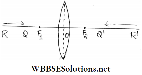
Suppose, a narrow beam of rays parallel to the principal axis is incident on a lens’
- If the lens is convex, the beam of rays after refraction verges to a point on the principal axis. This point is called the principal focus of the lens.
- If the lens is concave, the beam of rays after refraction appears to diverge from a point on the principal axis. This point is called the principal focus of the lens.
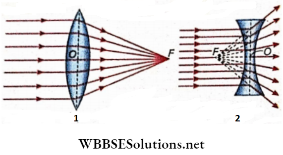
The point F is the principal focus of the lens. A lens has two principal foci. Here in either case point F is the second principal focus of the lens. In addition to this principal focus a lens has another principal focus which is called the first principal focus.
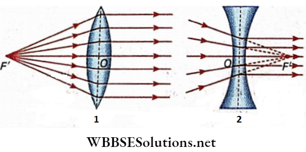
1. First principal focus:
- In the case of a convex lens: The first principal focus is a point on its principal axis such that the rays diverging from it emerge parallel to the axis after refraction through the lens.
- In the case of a concave lens: The first principal focus is a point on its principal axis such that the rays directed towards it emerge parallel to the axis after refraction through the lens. The point F’ is the first principal focus.
2. The second principal focus is conventionally called the principal focus of a lens:
Focal Length
The distance of the principal, focus from the optical centre of a lens is the focal length F of that lens.
1. The first principal focal length:
Is the distance of the first principal focus from the oj$cal centre. The second principal focal length is the distance of the second principal focus from the optical centre.
The point O Is the optical centre.
OF’ = First principal focal length of the lens
OF = Second principal focal length of the lens
2. The second principal focal length Is conventionally taken as the focal length of a lens:
The value of the focal length of the lens depends on the colour of light, the lens medium and also on the surrounding medium. If the media on both sides of the lens are the same, then it can be proved that the first principal focal length (f1) and the second principal focal length (f2) are equal. But if the media are different on both sides, then these two lengths would be different.
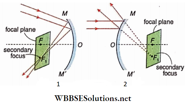
Focal plane
A plane perpendicular to the principal axis of a lens drawn through the principal focus is known as the focal plane of a lens.
A lens has two focal planes corresponding to its two focal points. The focal plane through the first principal focus is called the first principal focal plane and the plane through the second principal focus is called the second principal focal plane.
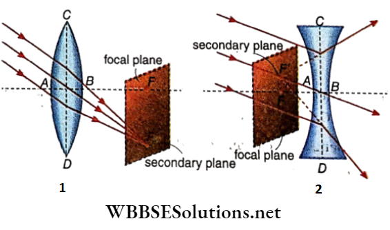
Secondary focus
Suppose a beam of parallel rays inclined at a small angle with the principal axis of a lens is incident on it. The point on the focal plane to which the beam converges (in the case of the convex lens) and from which the beam appears to diverge (in the case of the concave lens) after refraction is called the secondary focus of the lens.
The point F’ is the secondary focus of the lens. It Is to be noted that the principal focus of a convex or concave lens Is a fixed point, but the secondary focus is not a fixed point. With the change of the angle of inclination of the incident rays with the principal axis of the lens, the position of the secondary focus changes. However the secondary focus always remains on the focal plane.
- Aperture: The boundary line of the planes of a lens is circular and the diameter of the circle is ordinarily called the aperture of the lens. In the diameter CD Is the aperture of the lens.
- Thin lens: A thin lens Is one in which the thickness at the principal axis Is small compared with the radii of curvature of the two surfaces
Refraction through spherical surfaces physics notes
Refraction Of Light At Spherical Surface Lens Determination of the Position Of An Image By Geometrical Method
In all the following discussions the lenses we shall deal with are thin lenses with small aperture.
To find the position of the image of an extended object placed on the principal axis of a lens
By the geometrical method, we should remember the following facts:
- A ray falling on a convex lens in a direction parallel to the principal axis converges to the second principal focus after refraction by the lens and a ray falling on a concave lens in a direction parallel to the principal axis appears to diverge from the second principal focus after refraction by the lens.
- A ray passing through the first principal focus of a convex lens or proceeding to the first principal focus of a concave lens will emerge parallel to the principal axis after refraction through it.
- A ray passing through the optical centre of a convex or a concave lens emerges out from the lens undeviated and undisplaced with respect to the direction of incidence as the concerned lens is a thin lens.
Using any two rays of the above-mentioned three rays, the image Q of an object can be drawn, images have been drawn in different cases applying this method. These diagrams are called ‘Ray diagrams’
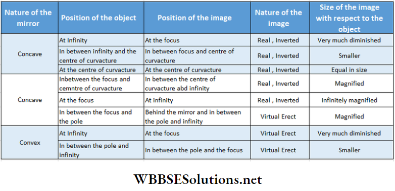
Refraction Of Light At Spherical Surface Lens Position Size And Nature Of The Image For Different Positions Of An Object
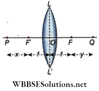
For any particular surrounding media (here, air), the position, size and nature of the image of an object formed by refraction in a lens depend on the position of the object with respect to the lens. How the position and nature of the Image change when the object is brought from infinity up to a position dose to the lens is shown below. For the convenience of discussion, we shall consider the object PQ to be placed perpendicular to the principal axis of the lens LL’ .{f is taken as the focal length of the lens).
In the case of convex lens
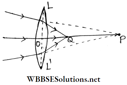
1. Object is placed at infinity:
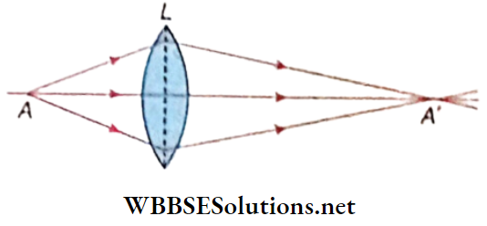
If the object is at infinity, the rays of light from a point on the object may be considered parallel. The beam of parallel rays inclined at a small angle with the principal axis of the convex lens converges at this point p on the second principal focal plane after refraction the lens. So, the image is formed in the focal plane and it is real, inverted and infinitely diminished.
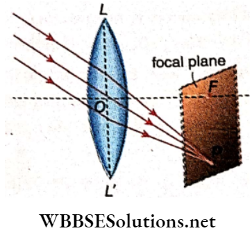
Use: The objective of a telescope is made by using this prop of the convex lens.
2. Object is placed between infinity and 2 f:
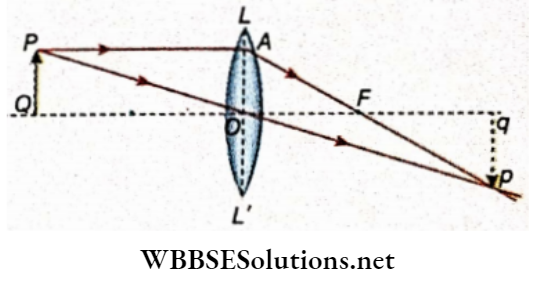
The object PQ is placed perpendicular to the principle axis of the convex lens LL’ and at a distance greater than 2f from the lens
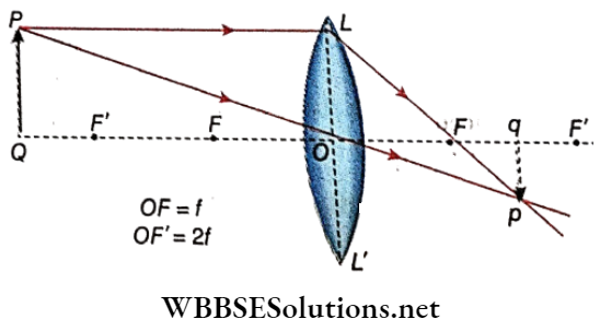
A ray travelling parallel to the principal axis the refraction through the lens passes through the focus F’ Another ray from p goes straight through the Optical centre O . These two refracted rays meet at the point p which is the image of p, from p, pq is drawn perpendicular to the principle axis Obviously, q is the image of the foot Q of the object. So, pq is the image of PQ.
3. Object is placed at 2f:
The object PQ Is placed per appendicular to the principal axis of the convex lens I, If and is a distance 2f from the Leon A ray from travelling parallel to the principal axis air refraction through the lens passes through the focus P, Another ray from P goes straight through the optical centre Q, These two refracted rays meet at the point p which is the image of P from p, pq IN drawn perpendicular to the principal axis. Q Is the Image of the foot Q of the object. So, pq Is the image of PQ.
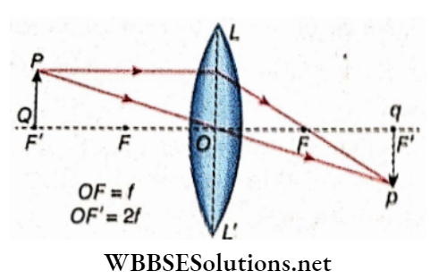
Therefore, the image is formed on the side of the lens opposite to that of the object at a distance of 2f from the lens. The Image Is real, inverted and equal In size to the object
Use: In terrestrial telescope, this property of the convex lens Is utilised to convert the inverted Image Into an erect image of the same size.
4. Object is placed between f and 2f:
The object PQ is placed perpendicular to the principal axis of the convex lens LL’ and is placed between f and 2f, A ray from P travelling parallel to the principal axis after refraction through the lens passes through the focus P. Another ray from P goes straight through the optical centre 0. These two refracted rays meet at the point p which is the Image of P. From p, pq Is drawn perpendicular to the principle axis q is the image of the foot Q of the object. So pq is the images of PQ.
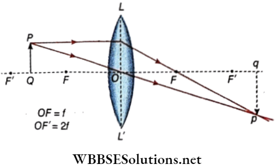
Therefore, die Image In formed on the side of the lens opposite to that of the object and at a distance greater than 2f. The image is real, inverted and magnified i size with respect to the object
Use: The objective of a microscope Is made by utilising this property of the convex lens.
5. Object Is placed at:
The Object PQ is placed perpendicular to the principal axis of the convex lens LL’ and Is placed at focus. A ray from fi travelling parallel to the principal axis after refraction through the lens passes through DM focus V. Another ray from fi moves straight through Ilia optical centre O, these two refracted rays being parallel, the I Image of PQ Is assumed to be formed at infinity
Therefore, the linage Is formed at infinity on the side of the lens opposite to that of the object. The Image Is real, inverter and Infinitely magnified.
Use: The convex lens is utilised in the above way in such instruments whore the production of a parallel beam of rays is required. spectrometer parallel rays are produced in this way
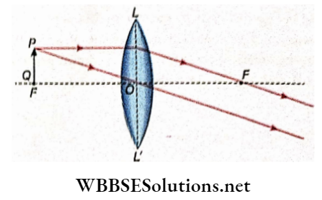
6. Object is placed between f and lens:
Is placed perpendicular to the principal axis of the convex le LL’ and Is placed between f and the lens. A ray free P travelling parallel to the principal axis after refraction through the lens passes through the focus F, Another ray horn I” moves straight through the optical centre 0. These two refracted rays are divergent. So when the two rays are produced backwards they meet at; which is the virtual Image of F. l; from p, pq is drawn perpendicular to the principal axis. So, pq Is the image of PQ.
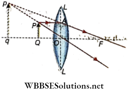
Therefore, the image Is formed on the same side of the lens as the object Is situated. The image is virtual, erect and magnified.
Use: Magnifying glass, eyepieces of microscope and telescope are made utilising this principle of the convex lens
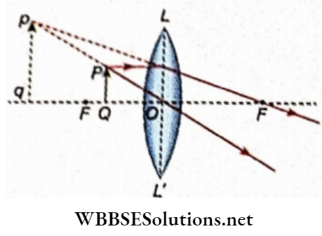
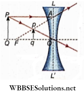
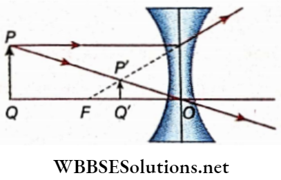
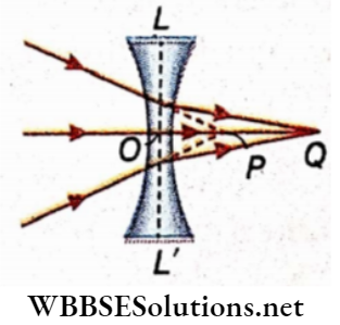
In the case of a concave lens
The object PQ is placed perpendicular to the principal axis of the concave lens LL’. A ray from P travelling parallel to the principal axis after refraction through the lens appears to diverge from the focus F. Another ray from P moves straight through the optical centre O.
The two refracted rays being divergent, when produced backwards, virtually meet at p. The point p from where the emergent rays appear to diverge after refraction through the lens is the image of P. From p, pq is drawn perpendicular to the principal axis. So, pq is the image of PQ
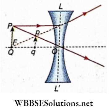
Therefore, the image is formed on the same side of the lens as the object is situated. The image is virtual, erect and diminished in size concerning the object.
The image moves from F to the lens and increases in size as the object is brought from infinity up to the lens. But the size of the page will always be less than the object
Inference: The following Inferences can be drawn from the above discussion.
- The virtual InutHo la formed on the Maine (tide of the lens as the object but the real Image IN formed on the aide of the lens opposite to that of the object.
- Virtual Image Is always erect and real Image Is always Inverted.
If half of a lens Is palmed black, the brightness of the Image produced by the lens reduces to half as the Image will be produced due to refraction through half portion of the lens. However, the size of the Image remains the same, because every half part of a lens forms a complete image of an object.
Method of Identifying Lenses
We know that if an object is placed very near to a convex lens l.o., within the focal length, then a virtual, erect and magnified Imago Is formed. On the other hand, when an object Is placed very near to a concaveÿ Ions a virtual, correct and diminished Imago Is formed. So, to Identify a lens easily will hold a linger In front of the lens and look at It from the other side of the lens. If the Image Is erect and magnified concerning the object the lens Is convex. But If the image Is erect but diminished In size, the lens Is concave
Refraction Of Light At Spherical Surface Lens Sign Convention
- Distances along the principal axis are to be measured from the optical centre of the lens.
- Distance from the optical centre) to be measured opposite to the direction of the incident ray are taken as negative and those to be measured in the direction of the incident ray are taken as positive. According to the above convention, the focal length of a convex lens is positive and that of a concave lens is negative.
- If the principal axis of the lens is taken as the x-axis, distances along the y-axis above the principal axis are taken as positive and distances along the y-axis below the principal axis are taken as negative
Assumptions are made during a discussion of refraction through the lens :
- The lens will be thin and its aperture will be small.
- Direction of incident ray will be shown from left to right i.e., the object should be considered to be placed on the left side of the lens.
- The optical centre O of the lens will be the origin of the cartesian frame of reference and the principal axis of the lens will be the x-axis
Refraction Of Light At Spherical Surface Lens General Formula Of Lens
The relation among object distance, image distance and focal length of a lens is known as the general formula of the lens.
Convex lens and real image
LL’ is a convex lens. An object PQ is placed perpendicular to the principal axis of the A ray from P travelling parallel to the; principal axis after refraction through the. leap passes through the second principal focus F. Another ray from P moves straight through the optical centre O. These two refracted rays meet at the point p which is the image of P. From p, pq is drawn per
Pendicular to the principal axis. So, pq is the image of PQ. This image is real and inverted
As the triangles POQ and pOq are similar
∴ \(\frac{P Q}{p q}=\frac{O Q}{O q}\) ……………………………….(1)
On the other hand, as the triangles AFO and pFq are similar,
∴ \(\frac{A O}{p q}=\frac{F O}{F q}\)
Or,\(\frac{P Q}{p q}=\frac{F O}{F q}\) ……………………………… (2)
AO = PQ
From equations (1) and (2) we, get
∴ \(\frac{O Q}{O q}=\frac{F O}{F q}\)
Or, \(\frac{O Q}{O q}=\frac{F O}{O q-O F}\) …………………… (3)
Now, according to sign convention, object distance = OQ = -u,
Image distance = Oq = +v, focal length = OF = +
Putting these values in equation (3) we get
Or , \(\frac{-u}{v}=\frac{f}{v-f}\)
Or, -uv+uf= vf
Or, -uf-vf = uv
Or, \(\frac{u f}{u v f}-\frac{v f}{u v f}=\frac{u v}{u v f}\)
Or, \(\frac{1}{v}-\frac{1}{u}=\frac{1}{f}\) ………………………(4)
Convex lens and virtual image
The object PQ is placed perpendicular, to the principal axis of the convex lens LL’ and is placed between the focus and the lens. So, the virtual image pq has been formed
As the triangles POQ and pOq are similar,
⇒ \(\frac{P Q}{p q}=\frac{O Q}{O q}\)
On the other hand, as the triangles AFO and pFq, they are similar
⇒ \(\frac{A O}{p q}=\frac{O F}{q F}\)
Or, \(\frac{P Q}{p q}=\frac{O F}{q F}\) …………………….. (6)
[AO = PQ]
From equations (5) and (6) we get
⇒ \(\frac{O Q}{O q}=\frac{O F}{q F} \text { or, } \frac{O Q}{O q}=\frac{O F}{O q+O F}\) …………………. (7)
Now, according to sign convention, object distance =OQ -~u , image distance – Oq = -v, focal length = OF = +f
Putting these values in equation (7) we get
⇒ \(\frac{-u}{-v}=\frac{f}{-v+f}\)
or, uv-uf= -vf Or, uf- vf = uv
Or, \(\frac{u f}{u v f}-\frac{v f}{u v f}=\frac{u v}{u v f}\)
Or, \(\frac{1}{v}-\frac{1}{u}=\frac{1}{f}\) ……………………. (8)
The focal length of a convex is taken as positive, In the formation of a real image of a real object, u is negative but v is positive. So the formation of a real image of a real objective by a convex lens the modified form of the general formula is as follows.
⇒ \(\frac{1}{v}-\frac{1}{-u}=\frac{1}{f} \text { or, } \frac{1}{v}+\frac{1}{u}=\frac{1}{f}\)
Concave lens and virtual image
LL’ is a concave lens, An object PQ is placed perpendicular to the principal axis of the lens. A ray from P travelling parallel to the principal axis after refraction through the lens appears to diverge from the focus F. Another ray from P moves straight through the optical centre O. The two refracted rays virtually meet at p, The point p from where the emergent rays appear to diverge after refraction through the lens is the image of P. From p, pq is drawn perpendicular to the principal axis. So, pq is the Image of PQ. The image is virtual and erect
As the triangles POQ and pOq are similar,
⇒ \(\frac{P Q}{p q}=\frac{O Q}{O q}\)
On the other hand, as the triangle APQ and ppq are similar
⇒ \(\frac{A O}{p q}=\frac{O F}{q F}\)
Or, \(\frac{P Q}{p q}=\frac{O F}{q F}\) ………………………………….. (10)
[AO = PQ]
From equations (9)and (10) we get,
⇒ \(\frac{O Q}{O q}\)
= \(\frac{O F}{q F} \text { or, } \frac{O Q}{O q}=\frac{O F}{O q+O F}\) ………………………… (11)
Now, according to sign convention , object distance = OQ = -u , image distance = Oq = -v, focal length = OF = -f
Putting these values in equation (11) we get,
⇒ \(\frac{-u}{-v}\) = \(\frac{-f}{-f+v}\)
Or, uf – uv= vf
Or, uf- vf= uv
Or, \(\frac{u f}{u v f}-\frac{v f}{u v f}=\frac{u v}{u v f}\)
Or, \(\frac{1}{v}-\frac{1}{u}=\frac{1}{f}\) ………………………….. (12)
This is the conjugate foci relation of the lens, also known as the general formula of the lens.
The term conjugate means that the two points are Interchangeable, This follows from the principle of reversibility of light path. For these lenses the distance of conjugate foci l.e., u and v are given by the relation \(\frac{1}{v}-\frac{1}{u} \equiv \frac{1}{f}\) So this relation Is often called conjugate foci relation.
Refraction Of Light At Spherical Surface Lens Magnification Of The Image Formed By Lens
Linear or Transverse or Lateral Magnification of the Image of an Object Kept Perpendicular to the Principal Axis
Linear Magnification Definition:
Linear magnification of an image formed by a lens is defined as the ratio of the size of the image to the size of the object
Denoting linear magnification by m we have, from and
m = \(\frac{\text { size of image }(I)}{\text { size of object }(O)}=\frac{p q}{P Q}\)
= \(\frac{v}{u}=\frac{\text { image distance }}{\text { object distance }}\)
According to sign convention:
- For the formation of a real image in a convex lens u is negative and v is positive. So linear magnification m is negative. The image is inverted
- For the formation of a virtual image in a convex lens both u and v are negative. So linear magnification m is positive. The image is erect.
- In the case of a concave lens both u and v are negative, So linear magnification m is positive. So the image is erect.
So we can say that if magnification is negative, the image is inverted and if magnification is positive, the image is erect
We can determine the expression for the magnification of an image formed by a lens by the same process as adopted for the determination of the magnification of an image formed by the reflection oflight on a curved surface.
It is to be noted that the real image formed by reflection is formed in front of the mirror i.e. on the same side of the mirror as the object. But in the case of a lens, the real image formed by a lens due to refraction is formed on the opposite side of the real object.
The general expression for magnification of the image formed by refraction in the lens is given by
m = \(\frac{I}{O}=\frac{v^2}{u}\)
Magnification produced by a combination of lenses:
The magnification of the final image produced by a combination of lenses is given by m = m1 × m2 × m3; where m1,m2,m3,…… etc..are respectively the magnifications produced by each lens.
Areal Magnification of the image is kept perpendicular to the principal axis
Areal Magnification Definition:
Linear magnification of an image formed by a lens is defined as the ratio of the size of the image to the size of the object.
Let the length and breadth of a two-dimensional object be l and b respectively. Hence, the area of object A = lb
If the linear magnification of the image is m, the length of the image l’ = mx l and the breadth of the image b’ = m × b
Area of the image, A’ = l’b’ = m²lb = m²A
Therefore areal magnification
m’ = \(\frac{A^{\prime}}{A}=m^2\) …………………. (1)
Longitudinal or Axial Magnification of the Image of an Object Kept Along the Principal Axis
Axial Magnification Definition:
Longitudinal or Axial magnification of the image formed by a lens of an object kept along the principal axis is defined as the ratio of the length of the image to that of the object.
Let an extended object is kept along the principal axis of a vex lens.
Let u1 and u2 be the distances of the nearest and the furthest points respectively of the object along the principal axis and v1 and v2 the respective image distances
Longitudinal magnification m” = \(\frac{v_2-v_1}{u_2-u_1}=\frac{\Delta v}{\Delta u}\)
For infinitesimal values of Δv and Δu, magnification should be noted a \(\frac{d v}{d u}\)
Differentiating the lens equation, \(\frac{1}{v}+\frac{1}{u}=\frac{1}{f}\) , with respect to u we get,
⇒ \(-\frac{1}{v^2} \frac{d v}{d u}-\frac{1}{u^2}\) = 0 [ f is constant]
Or, \(\frac{d v}{d u}=\frac{-v^2}{u^2}\)
m” = \(\frac{d v}{d u}=-m^2\) …………………………..(1)
Longitudinal magnification =- (linear magnification)²
Hence, longitudinal magnification in the case of the lens is numerically equal to the square of linear magnification.
It is dear from equation (1) that m” is always negative irrespective of the sign of m. This implies that object and image always lie in opposite directions along the principal axis, whatever may be the nature of the image real or virtual, in a convex or concave lens. This matter is called axial change
Relation of f and v or f and u with m
The lens formula is
⇒ \(\frac{1}{\nu}-\frac{1}{u}=\frac{1}{f}\) …………………………………… (1)
Or, \(1-\frac{\nu}{u}=\frac{p^{\prime}}{f} \text { or, } 1-m=\frac{\nu}{f}\)
Or, m = \(1-\frac{\nu}{f} \text { or, } m=\frac{f-\nu}{f}\)
Again, from equation (1) we get,
⇒ \(\frac{u}{\nu}-1=\frac{u}{f} \text { or, } \frac{1}{m}-1=\frac{u}{f}\)
Or, \(\frac{1}{m}=1+\frac{u}{f} \text { or }, \frac{1}{m}=\frac{f+u}{f}\)
m = \(\frac{f}{u+f}\)
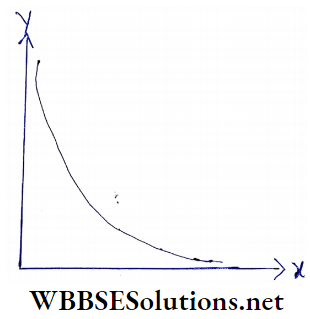
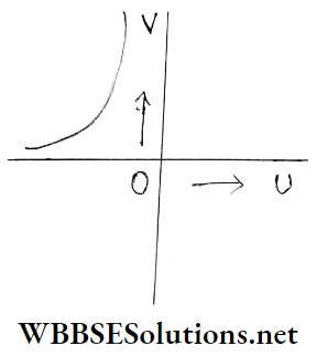
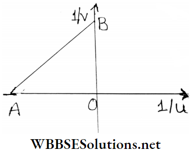
u-v And \(\frac{1}{u} \frac{1}{v}\) Graphs For Convex Lens
The focal length of convex lens f is positive. The real image formed by this lens is always situated on the side opposite to the object So image distance v is also positive. According to the sign convention object distance u is negative. Hence if a real image is formed by a convex lens the equation of the lens is as follows
⇒ \(\frac{1}{v}-\frac{1}{-u}=\frac{1}{f} \text { or, } \frac{1}{v}+\frac{1}{u}=\frac{1}{f}\)
1. u – v graph: In the case of a convex lens if different values of object distances and the corresponding image distances are recorded and plotted on a graph, It will be a rectangular hyperbola
2. \(\frac{f}{u+f}\) graph:
In case a convex lens if \(\frac{1}{u} \sim \frac{1}{v}\)graph Is drawn taking different values of u and v, It will be a straight line The intercept cut by the straight line AB from the axes are each equal to \(\frac{1}{f}\)
i.e OA = OB = \(\frac{1}{f}\)
Numerical Examples
Example 1. The distance of an object from a convex lens is 20 cm. If the focal length of the lens is 15 cm determines the position of the image and its nature.
Solution:
Here, u = -20 cm ; as the lens is convex,f = +15 cm
We know, \(\frac{1}{v}-\frac{1}{u}=\frac{1}{f}\)
Or, \(\frac{1}{v}=\frac{1}{u}+\frac{1}{f}=\frac{1}{-20}+\frac{1}{15}\)
= \(\frac{4-3}{60}=\frac{1}{60}\)
Or, v = 60 cm
As v is positive, the image will be formed on the side opposite to the object at a distance of 60 cm i.e., the image is real.
Magnification, m = \(\frac{v}{u}\frac{60}{-20}\) = -3
So, an image magnified three times as the size of the object is formed. As magnification is negative, the image is inverted
Example 2. If an object is placed at a distance of 30 cm from a lens, a virtual image is formed. If the magnification of the image Is, find the position of the image and the focal length of the lens. Also, find the nature of the lens
Solution:
Here, object distance, u = -30 cm ; magnification
m = \(\frac{1}{v}-\frac{1}{u}=\frac{1}{f}\)
Or, \(\frac{u}{v}-1=\frac{u}{f}\)
Or, \(\frac{1}{m}-1=\frac{u}{f}\)
Substituting m = \(\frac{2}{3}\) u = -30 we get,
⇒ \(\frac{3}{2}\)– 1 = \(\frac{3}{2}-1=\frac{-30}{f}\), or, f = -30 × 2 = -60 cm
The focal length of the lens is 60 cm.
Further, the negative sign of f implies that the lens is a concave one
Important Definitions Related to Lens Refraction
Example 3. A convex lens forms a real image of an object magni¬ fied n times. Prove that the object distance =(n+ 1) \(\frac{f}{n}\) , f = focal length of the lens
Solution:
Here, magnification =n
i.e, \(\frac{v}{u}\) = n or, v = nu
For a real object, is negative and v is positive. For a convex lens f is positive. Following this sign convention, we get from the lens formula
⇒ \(\frac{1}{v}-\frac{1}{u}=\frac{1}{f}\)
Or, \(\frac{1}{n u}+\frac{1}{u}=\frac{1}{f}\)
or, u = \(\frac{1+n}{n u}=\frac{1}{f}\)
u = (n+1)\(\frac{f}{n}\)
i. e the object distance is (n+1)\(\frac{f}{n}\)
Example 4.
1. A luminous object and a screen are placed 90 cm apart. To cast an image magnified twice the size of the object on the screen, what type of lens is required and what will be its focal length?
2. An object Is situated at a distance of 10 in from the convex lens. A magnified Image Is cast on a screen by the lens. Its magnification Is 19 what is the focal length of the lens
Solution:
Since The image is formed on a screen, it Is real. Hence lire lens to be used should be convex.
In this case, u + v = 90 cm
And \(\frac{v}{u}\) = 2 or, v = 2u
∴ 3u = 90 cm
or, u = 30 cm
∴ v= 90- 30 = 60 cm
Substituting in lens formula, \(\frac{1}{v}-\frac{1}{u}=\frac{1}{f}\)
Or, \(\frac{1}{60}-\frac{1}{-30}=\frac{1}{f}\) [
u = – 30, as the object is real
Or, f = 20 cm
The focal length of the lens is 20 cm.
Magnification , m = \(\frac{v}{u}\) = 19
v = 19 u = 19 × 10 = 190m
Substituting v = 190 and u – 10 in \(\frac{1}{v}-\frac{1}{u}=\frac{1}{f}\)
We get, \(\frac{1}{190}+\frac{1}{10}=\frac{1}{f}\) Or, f = \(\frac{190}{1+19}\) = 9.5 m1
∴ The focal length of the lens is 9.5 m.
Example 5. A convex lens is placed just above an empty vessel. Ait object is placed at the bottom of the vessel and at u distance of 45 cm below the lens. An image of the object is formed above the vessel at a distance of 36 cm front die lens. A liquid is poured up to a height of 40 and cut lit the vessel. Now the image is formed above the vessel at ! a distance of 48 cm from the lens. Calculate the refractive index of the liquid
Solution:
When the vessel is empty, u = (-45) cm , v = 36 cm From the equation of the lens we get
⇒ \(\frac{1}{v}-\frac{1}{u}=\frac{1}{f}\)
Or, \(\frac{1}{+36}-\frac{1}{-45}=\frac{1}{f}\)
Or, \(\frac{+9}{180}=\frac{1}{f}\)
Or, f = + 20 cm
On pouring the liquid into the vessel the apparent position of the object will be raised.
Real depth of the liquid = 40 cm and apparent depth = cm (say)
If the refractive index of the liquid is fi, then
μ = \(\frac{\text { real depth }}{\text { apparent depth }}=\frac{40}{x}\)
⇒ \(\frac{40}{\mu}\)
Or, x = \(\frac{40}{\mu}\)
Now, distance of the lens from the liquid surface = 45-40 = 5 cm
Object distance from the lens = (5 + x) = 5 + \(\frac{40}{\mu}\)
In this case, v = +48 cm and f = +20 cm
From the equation of the lens
⇒ \(\frac{1}{v}-\frac{1}{u}=\frac{1}{f}\)
⇒ \(\frac{1}{48}-\frac{1}{-\left[5+\frac{40}{\mu}\right]}=\frac{1}{20}\)
Or, \(\frac{1}{48}+\frac{1}{5+\frac{40}{\mu}}=\frac{1}{20}\)
Or, \(\frac{1}{5+\frac{40}{\mu}}=\frac{1}{20}-\frac{1}{48}=\frac{7}{240}\)
⇒ \(5+\frac{40}{\mu}=\frac{240}{7}\)
⇒ \(\frac{40}{\mu}=\frac{240}{7}-5\)
⇒ \(\frac{40}{\mu}=\frac{205}{7}\)
⇒ \(\frac{280}{205}\)
= 1.366
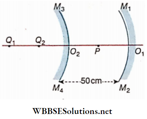
Example 6. Two convex lenses of focal lengths 15 cm and 10 cm are placed coaxially. A ray of light parallel to the principal axis of a lens is incident on it and emerges from the other lens parallel to the same axis. Draw a neat ray – diagram. What is the distance of separation between the lenses?
Solution:
The ray incident on the lens Ly passes through the second principal focus of this lens after refraction. Since the ray after refraction through the second lens moves parallel to the principal axis of this lens, F is the first principal focus of lens L2
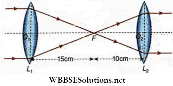
O2F = 15 cm , O2 F = 10 cm
Distance of separation between the lenses
= 15 + 10 = 25 cm
Example 7. If an object is placed at a distance of 20 cm in front of a convex lens, three times magnified and an Inverted Image is formed. In which direction and how far Is the lens to be moved to obtain an erect Image of equal magnification [m = 3] T
Solution:
Here, m = 3 and u = 20 cm
Here, m = 3 and u = 20 cm
⇒ \(\frac{v}{u}\)= 3
Or, v = 3u = 3 × 20 = 60 cm
Now \(\frac{1}{v}-\frac{1}{u}=\frac{1}{f}\)
⇒ \(\frac{1}{60}-\frac{1}{-20}=\frac{1}{f}\)
Following sign convention, u = -20 cm and v = 60 cm
Or, f = 15 cm
To obtain an erect image, the lens is to be moved towards the object, so that the object distance now becomes less than the focal distance of the lens
Let the lens is moved x cm towards the object
So, the object distance becomes, u1 = (20 -x) cm
Let the image distance be v1 cm
⇒ \(\frac{v_1}{u_1}\) = m = 3
Or, v1 = 3u1 = 3(20- x) cm
From the lens equation following the sign convention we have,
⇒ \(\frac{1}{v_1}-\frac{1}{u_1}=\frac{1}{f} \text { or, } \frac{1}{-3(20-x)}-\frac{1}{-(20-x)}\)
= \(\frac{1}{15}\) [as the image is virtual and so v1 is taken as negative]
Or, \(\frac{2}{3(20-x)}=\frac{1}{15}\)
Or, x = 10 cm
∴ The lens is to be moved by a distance of 10 cm towards the lens
Example 8. If a magnifying lens of focal length 10 cm is held in front of very small writing, It is magnified five times. How far was the magnifying lens held?
Solution:
Here, focal length, f = 10 cm
Let object distance = u
Now, magnification, m = \(\frac{v}{u}\) – = 5, or, v = 5u
Now \(\frac{1}{v}-\frac{1}{u}=\frac{1}{f}\)
⇒ \(\frac{1}{-5 u}-\frac{1}{-u}=\frac{1}{10}\)
[For magnifying lens, u and v both are negative]
Or, \(-\frac{1}{5 u}+\frac{1}{u}=\frac{1}{10}\)
Or, \(\frac{4}{5 u}=\frac{1}{10}\)
Or , u = 8 cm
So, the lens was held at a distance of 8 cm from the writing
Example 9. An object is placed at a distance of 150 cm from a screen. A convex lens is placed between the object and the screen so that an image magnified 4 times the object is formed on the screen. Determine the position of the lens and its focal length
Solution:
Here, u + v – 150 cm
And magnification, m = 4 or, – = 4 or, v = 4h
From equation (1) we have,
u + 4u = 150
Or, 5u = 150 or, u = 30 cm
∴ v = 4 × 30 = 120 cm
Hence, the distance of the lens from the screen = 120 cm
Now, \(\frac{1}{v}-\frac{1}{u}=\frac{1}{f}\)
Or, \(\frac{1}{120}-\frac{1}{-30}=\frac{1}{f}\)
Since the object and the image are situated on mutually opposite sides of the lens, u = -30 cm, v = 120 cm
⇒ \(\frac{1}{120}+\frac{1}{30}=\frac{1}{f}\)
Or, \(\frac{1}{f}=\frac{1+4}{120}\)
= \(\frac{5}{120}\)
or, f = 24 cm
The focal length of the lens is 24 cm.
Example 10. A convex lens of focal length f forms an image which is m times magnified on a screen.If the distance of the object and the screen is x, prove that f = \(\frac{m x}{(1+m)^2}\)
Solution:
Since the image is formed on a screen, it is real. So the image distance is positive. The focal length is also positive. Object distance is negativeMagnification, m = “ or; v
Magnification, m = \(\frac{v}{u}\) or; v = mu
Here u+v = x Or, U+ mu = x Or, u= \(\)
v = \(\frac{m x}{1+m}\)
The equation of lens \(\frac{1}{v}-\frac{1}{u}=\frac{1}{f}\)
⇒ \(\frac{1}{m u}+\frac{1}{u}=\frac{1}{f}\) Or, \(\)
Or, f = \(\frac{m u}{1+m}=\frac{m x}{(1+m)^2}\)
Since u = \(\frac{x}{1+m}\)
Example 11. An object is placed on the left side of a convex lens A of focal length 20 cm at a distance of 10 cm from the lens. Another convex lens of focal length 10 cm is placed co-axially on the right side of lens A at a distance of 5 cm from it Determine magnification and position of the final image by the lens combination. Solution; In case of image formation by the first lens, u cm; f = 20 cm, v =?
Solution:
Now, \(\frac{1}{v}-\frac{1}{u}=\frac{1}{f}\)
⇒ \(\frac{1}{v}-\frac{1}{-10}=+\frac{1}{20}\)
⇒ \(\frac{1}{v}=\frac{-1}{10}+\frac{1}{20}=\frac{-1}{20}\)
v = -20cm
Since v is negative, a virtual image would form on the same side of the object at a distance of 20 cm from the lens.
This image will act as the object for the second lens.
In the case of image formation by the second lens,
u= -(20+5) = -25 cm,
f= 10 cm,
v =?
From the equation of lens,
⇒ \(\frac{1}{v}-\frac{1}{u}=\frac{1}{f}\)
⇒ \(\frac{1}{v}-\frac{1}{-25}=\frac{1}{10}\)
⇒ \(\frac{1}{v}=\frac{-1}{25}+\frac{1}{10}=\frac{3}{50}\)
Or, v = \(\frac{50}{3}\)
= 16.66
So, finally, a real image is formed on the right side of the second lens (on the opposite side of the object) at a distance of 16.66 cm from this lens.
Magnification by the first lens
m1 = \(\frac{v}{u}=\frac{20}{10}\)
= 2
And magnification by the second lens
m2 = \(\frac{v}{u}=\frac{50}{3 \times 25}\)
= \(\frac{2}{3}\)
Magnification by the lens combination
m = m1 × m2
= 2 × \(\frac{2}{3}\)
= \(\frac{4}{3}\)
= 1.33
Example 12. A convex lens forms a real image of an object magnified 10 times. If the focal length of the lens is 20cm, determine the distance of the object from the lens
Solution:
Let object distance = x
Here, m= 10
∴ \(\frac{v}{x}=10\)
Or, v = 10 x
In this case, v is positive and f = 20 cm
From The Equation of the Lens
⇒ \(\frac{1}{v}-\frac{1}{u}=\frac{1}{f}\)
Or, \(\frac{1}{10 x}-\frac{1}{-x}=\frac{1}{20}\)
Or, \(\frac{11}{10 x}=\frac{1}{20}\)
Or, x = 22cm
Object distance = 22cm
Examples of Applications of Spherical Lenses in Optics
Example 13. Two convex lenses of focal lengths 3cm and 4cm are placed 8cm apart from each other. An object of height Icm Is placed In front of a lens of smaller focal length at a distance 4cm. Determine the magnification and size of the final image by the lens combination.
Solution:
In the case of image formation by the first lens, u = -4cm,f = 3cm
Now, \(\frac{1}{\nu}-\frac{1}{u}=\frac{1}{f}\)
Or, \(\frac{1}{v}+\frac{1}{4}=\frac{1}{3}\)
Or, \(\frac{1}{\nu}=\frac{1}{3}-\frac{1}{4}=\frac{1}{12}\)
Or, v = 12 cm
Since v is positive, an image would form on the side of the first lens opposite that of the object. This image acts as a virtual image for the second lens.
In the case of image formation by this lens
u = (12-8) = 4cm , f = 4 cm , v= ?
From the equation of lens
⇒ \(\frac{1}{v}-\frac{1}{u}=\frac{1}{f}\)
⇒ \(\frac{1}{v}-\frac{1}{4}=\frac{1}{4}\)
Or, \(\frac{1}{v}=\frac{1}{4}+\frac{1}{4}\)
⇒ \(\frac{1}{2}\)
Or v = 2cm
So, the final image is real and it will be formed at a distance 2cm from the second lens.
Magnification by the first lens
m1 = \(\frac{v}{u}=\frac{12}{4}\)
m1 = 3
Magnification by the second lens
m2 = \(\frac{v}{u}=\frac{2}{4}\)
m2 = \(\frac{1}{2}\)
So, magnification by the lens combination
m = m1 × m2 = \(3 \times \frac{1}{2}=\frac{3}{2}\)
Again m = \(\frac{\text { size of image }}{\text { size of object }}\)
Or, \(\frac{3}{2}=\frac{\text { size of image }}{1}\)
Or, size of image = \(\frac{3}{2}\)
= 1.5 cm
Image Of A Virtual Object
We have so far discussed the image formation of real objects. But objects may be virtual as well and images of the virtual objects can be formed by using lenses.
A converging beam of rays is incident on a convex lens and a concave lens respectively. In the absence of the lenses, the converging beam of rays would meet at Q on the other side of the lenses but due to the presence of the lenses the beam meets at Q’. So, Q is a virtual object here and its image Q’ is a real
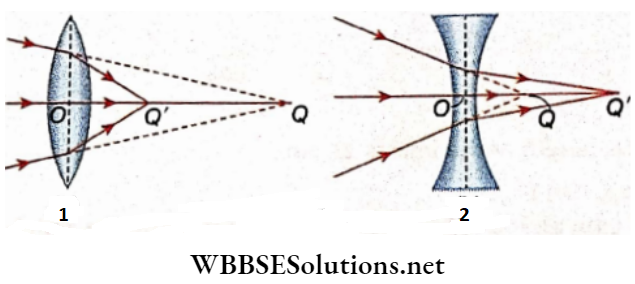
After refraction in the convex lens, a convergent beam of rays becomes more convergent i.e., the convergent beam meets nearer to the lens. In the case of the convex lens, Q’ is nearer to the lens than Q . Obviously in this case image distance, OQ’ is less than object distance, OQ. In a convex lens, the real image of a virtual object is formed and the image lies within the focus
After refraction in the concave lens, a convergent beam of rays becomes less convergent i.e., the convergent beam meets further away from the lens. In the case of a concave lens Q’ is more distant from the lens than Q . Obviously in this case image distance, OQ’ is greater than object distance, OQ.
But if the virtual object distance, OQ is greater than the focal length of the concave lens, the image formed by the concave lens becomes virtual.
Remember that virtual object distance is positive.
Example 1. If a convex lens of focal length 20 cm is placed in the path of a convergent beam of rays, the beam meets at Q. In the absence of the lens, the beam would meet at P.If the distance of P from the lens- is 30 cm, determine the distance of Q from the lens
Solution:
The converging beam of rays meets at Q after refraction in the lens LL’. In the absence of the lens the beam would meet at P In this case concerning the lens, P is the virtual object and Q is its real image
Here, u = 30 cm , f= 20 cm , v = OQ = ?
The equaton of lens is = \(\frac{1}{v}-\frac{1}{u}=\frac{1}{f}\)
⇒ \(\frac{1}{v}-\frac{1}{30}=\frac{1}{20}\)
Or, \(\frac{1}{v}=\frac{1}{30}+\frac{1}{20}=\frac{1}{12}\)
Or, v =12cm
Required distance OQ = 12cm
Example 2. A converging beam of frays after refraction in a concave lens of focal length 20 cm meets at a distance of 15 cm from the lens. In the absence of the lens, where would the beam meet?
Solution:
In the absence of the lens, the converging beam would meet at P. So, concerning this lens P is the virtual object and Q is its real image
In this case, v = OQ – 15 cm; f= -20 cm
The equation of lens is \(\)
⇒ \(\frac{1}{15}-\frac{1}{u}=-\frac{1}{20}\)
Or, \(\frac{1}{u}=\frac{1}{20}+\frac{1}{15}\)
u = \(\frac{60}{7}\) = 8.57 cm
Therefore, in the absence of the lens, the beam of rays would meet at a distance of 8.57 cm from the lens.
Refraction Of Light At Spherical Surface Lens Newton’s Equation
Let II’ be a convex lens. F, F’ and O are the second principal focus, the first principal focus and the optical centre of the lens respectively. P and Q are the point object and point image respectively
Here, OF = OF’ = f; PF’ = x and QF = y; object distance, OP = -u = and image distance,
OQ – v = y+f
The equation of the lens is
⇒ \(\frac{1}{v}-\frac{1}{u}=\frac{1}{f}\)
⇒ \(\frac{1}{y+f}+\frac{1}{x+f}=\frac{1}{f}\)
Or, \(\frac{x+f+y+f}{(y+f)(x+f)}=\frac{1}{f}\)
or, (y +f)(x +f) = f(x + y + 2f)
or, xy + xf+ yf+f² = xf+ yf+ 2f² or, xy = f²
This is Newton’s equation in the case of lens.
For any lens, f is a constant quantity. Hence, an x- y graph supporting Newton’s equation will be a rectangular hyperbola.
Refraction Of Light At Spherical Surface Lens Lens Makers Formula For Thin Lens
The lens maker’s formula involves the focal length, the refractive index of the material of the lens, and the radius of curvature of the two surfaces of the lens. This formula is derived from the refraction of light on the two spherical surfaces of a lens.
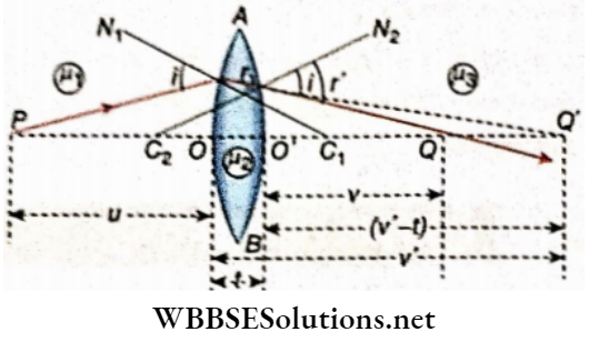
In refraction of light at the two spherical surfaces of a biconvex lens has been shown. P is the point object on the principal axis of the lens; Q’ is the image formed due to the refraction of light at die first surface of the lens and Q is the final image
Let μ1 = Refractive index of the medium in which the object is placed
μ2 = Refractive index of the material of the lens
μ3 = Refractive index of the medium into which the final ray emerges
In the Gaussian system, the object distance is measured from the pole O of the first spherical surface, and the final image distance is measured from the pole O of the second spherical surface. Accordingly,
object distance, OP = -u
Image distance, OQ’ = v’
Final image distance, O’Q = v
Thickness of lens on the axis, OO’ = t
The radius of curvature of the first surface of the lens = r1
The radius of curvature of the second surface of the lens = -r2
Considering refraction at the first surface AOB of the lens we have,
⇒ \(\frac{\mu_2}{v^{\prime}}-\frac{\mu_1}{u}=\frac{\mu_2-\mu_1}{r_1}\) ……………. (1)
Both object and image are real
Considering refraction at the second surface AO’B of the lens we have,
⇒ \(\frac{\mu_3}{v}-\frac{\mu_2}{v^{\prime}-t}=\frac{\mu_3-\mu_2}{r_2}\) …………….(2)
The object is virtual and the image is real
If the lens is very thin i.e…… v’, then it can be neglected.
In that case, equation (2) becomes
⇒ \(\frac{\mu_3}{v}-\frac{\mu_2}{v^{\prime}-t}=\frac{\mu_3-\mu_2}{r_2}\) …………….(3)
Adding equations (1) and (3) we have,
⇒ \(\frac{\mu_3}{v}-\frac{\mu_1}{u}=\frac{\mu_2-\mu_1}{r_1}+\frac{\mu_3-\mu_2}{r_2}\) ……………. (4)
This is the general equation of the lens:
This formula has been obtained for the formation of real images by a convex lens. But this formula is equally applicable for the formation of virtual image by a convex lens or for the concave lens
If the surrounding medium is by air, then μ1 = μ3 = 1
Taking μ2 = μ for the r of the material, we have
⇒ \(\frac{1}{v}-\frac{1}{u}=(\mu-1)\left(\frac{1}{r_1}-\frac{1}{r_2}\right)\) ………… (5)
If the object is at infinity, the image will be formed at the principal focus
i. e if u = ∞, v= f
∴ \(\frac{1}{f}=(\mu-1)\left(\frac{1}{r_1}-\frac{1}{r_2}\right)\) ……………………. (6)
This is the lens maker’s formula.
Lens in the air
If the refractive index of a glass lens relative to air is Jig and the radii of curvature of the first and the second refracting surfaces are r1 and r2 respectively, the focal length of the lens is obtained from the following relation,
\(\frac{1}{v}-\frac{1}{u}=(\mu-1)\left(\frac{1}{r_1}-\frac{1}{r_2}\right)\) ………………… (7)
1. In the case of the biconvex lens: r1 is positive and r2 is negative,
So for this lens from equation (7) we have,
⇒ \(\frac{1}{f}=\left({ }_a \mu_g-1\right)\left(\frac{1}{r_1}+\frac{1}{r_2}\right)\) ……………………. (8)
If the lens is equi-convex, then r1 = r2 = r and in that case,
⇒ \(\frac{1}{f}=\left(a_g{ }_g-1\right)^{\frac{2}{r}}\) ……………….. (9)
2. In the case of the biconcave lens: r1 is native and r2 is positive.
So for this lens from equation (7) we have
⇒ \(\frac{1}{f}=-\left(a_a \mu_g-1\right)\left(\frac{1}{r_1}+\frac{1}{r_2}\right)\) ……………….. (10)
If the lens Is equt-concnvo, then r1 = r2 = r. In this case
⇒ \(\frac{1}{f}=-\left({ }_a \mu_g-1\right) \cdot \frac{2}{r}\) …………………………… (11)
Dependence of focal length on surrounding medium:
Let us suppose that a lens Is situated In a medium denser titan air. Suppose, the denser medium is water.
Now, If the focal lengths of the lens In air and water are fa and fa respectively, then
⇒ \(\frac{1}{f_a}=\left({ }_a \mu_g-1\right)\left(\frac{1}{r_1}-\frac{1}{r_2}\right) \text { and } \frac{1}{f_w}=\left({ }_w \mu_g-1\right)\left(\frac{1}{r_1}-\frac{1}{r_2}\right)\)
∴ r1 and r2 are the radii of curvature of the first and the second refracting surfaces respectively
⇒ \(\frac{\frac{1}{f_a}}{\frac{1}{f_w}}=\frac{\left({ }_a \mu_g-1\right)}{\left({ }_w \mu_g-1\right)}\)
Or, \(\frac{f_w}{f_a}=\frac{\left({ }_a \mu_g-1\right)}{\left({ }_w \mu_g-1\right)}\) ……………… (12)
Now , \(\frac{w^{\mu_g}}{1}=\frac{a^{\mu_g}}{a^{\mu_w}}\)
Or, \(\frac{a^\mu g}{w^\mu g}=a^\mu w>1\)
∴ \(w^{\mu_g}<{ }_a \mu_g\)
Or, \(w^{\mu_g-1}<_a \mu_g-1\)
From equations (12) and (13) we get,
⇒\(\frac{f_w}{f_a}\) >1 Or, fw >fa
So, the focal length of a lens increases with the Increase of optical density of the surrounding medium.
If a convex lens of focal length f is cut horizontally along its principal axis into two halves, each half will have a focal 1 length equal to/ because the radii of curvature of the two surfaces of the new parts have the same values as the original
Refraction Of Light At Spherical Surface Lens Lens Makers Formula For Thin Lens Numerical Examples
Example 1. Focal length The focal length of a glass lens in air is 5 cm. What will be its focal length In water? The refractive index of glass =1.51 and the refractive index of water =1.33.
Solution:
Let the focal length of the lens in air =fa radii of curvature of the two surfaces = r1 and r2
\(\frac{1}{f_a}\) = ( aμg– 1) \(\left(\frac{1}{r_1}-\frac{1}{r_2}\right)\)
Or, \(\frac{1}{5}=(1.51-1)\left(\frac{1}{r_1}-\frac{1}{r_2}\right)\)
Or, \(\frac{1}{r_1}-\frac{1}{r_2}=\frac{1}{5 \times 0.51}\)
= \(\frac{1}{2.55}\)
If the focal length of the lens In water Is fw, then
⇒ \(\frac{1}{f_w}=\left({ }_w \mu_g-1\right)\left(\frac{1}{r_1}-\frac{1}{r_2}\right)\)
Or, \(\frac{1}{r_1}-\frac{1}{r_2}=\frac{1}{5 \times 0.51}=\frac{1}{2.55}\)
⇒ \(\left(\frac{1.51}{1.33}-1\right) \times \frac{1}{2.55}\)
= \(\frac{0.18}{1.33} \times \frac{1}{2.55}\)
= \(\frac{1.33 \times 2.55}{0.18}\)
= 18.84 cm
Example 2. A convex lens(μ =1.5) Is Immersed. In water (μ = 1.33). Will the focal length of the lens change In water? If so, how?
Solution:
If the focal length of the convex lens In air Is fa, the refractive index of the material of the lens is and the radii of curvature of the two surfaces are r1 and r2, then following sign convention
\(\frac{1}{f_a}=+\left(a_a \mu_g-1\right)\left(\frac{1}{r_1}+\frac{1}{r_2}\right)\) ………………………… (1)
If the lens is immersed in water, the focal length of the lens will be changed. If the focal length of the lens when immersed in water is fw, then
\(\frac{1}{f_w}=+\left({ }_w \mu_g-1\right)\left(\frac{1}{r_1}+\frac{1}{r_2}\right)\) ……………………… (2)
Dividing equation (1) by equation (2)
⇒ \(\frac{\frac{1}{f_a}}{\frac{1}{f_w}}=\frac{a^{\mu_g-1}}{w^{\mu_g-1}}\)
Or, \(\frac{f_w}{f_a}=\frac{1.5-1}{1.1278-1}\)
wμg = \(\frac{a^{\mu_g}}{a^\mu}=\frac{1.5}{1.33}\)
= 1.1278
⇒ \(w^{\mu_{\mathrm{g}}}=\frac{a^{\mu_{\mathrm{g}}}}{a^{\mu_w}}=\frac{1.5}{1.33}=1.1278\)
⇒ \(\frac{0.5}{0.1278}\)
= 3.9 Or , fw = 3.9 fa
So, if the lens is immersed in water Its focal length will be about 4 times its focal length in air.
Example 3. The radii of curvature of two surfaces of a biconvex glass lens are 20 cm and 30 cm. What is its focal length in air and water Refraction index of glass = \(\frac{3}{2}\) refractive index of water = \(\frac{4}{3}\)
Solution:
If the focal length of the lens in air is fa and following sign convention, we have
⇒ \(\frac{1}{f_a}=\left({ }_a \mu_g-1\right)\left(\frac{1}{r_1}+\frac{1}{r_2}\right)\)
= \(\left(\frac{3}{2}-1\right)\left(\frac{1}{20}+\frac{1}{30}\right)\)
= \(\frac{1}{2} \times \frac{5}{60}=\frac{1}{24}\)
fa = 24 cm
Therefore, the focal length of the biconvex lens in air is 24 cm. If the focal length of the lens in water is fw, we have
⇒ \(\frac{1}{f_w}=\left({ }_w \mu_g-1\right)\left(\frac{1}{r_1}+\frac{1}{r_2}\right)\)
⇒ \(\left(\frac{9}{8}-1\right)\left(\frac{1}{20}+\frac{1}{30}\right)\)
⇒ \(\frac{1}{8} \times \frac{5}{60}=\frac{1}{96}\)
wμg= \(\frac{a^{\mu_g}}{a^{\mu_w}}=\frac{\frac{3}{2}}{\frac{4}{3}}=\frac{9}{8}\)
fw= 96 cm
So, the focal length of the lens in water is 96 cm
Example 4. A plano-convex lens has a radius of curvature 10. It focal length is 80 cm in water. Calculate the refractive index ofthe material ofthe lens. Given refractive index of water \(\frac{4}{3}\)
Solution:
Let the absolute refractive index of the material of the lens = n of the material concerning water = n1: absolute r. i of water = n’
Given, r1 = ∞ and r2 = -10 cm. The focal length of the planoconvex lens when immersed in water = 80 cm.
∴ \(\frac{1}{f}=\left(n_1-1\right)\left(\frac{1}{r_1}-\frac{1}{r_2}\right)\)
Or , \(\frac{1}{80}=\left(n_1-1\right)\left(\frac{1}{\infty}+\frac{1}{10}\right)\)
Or , n1– 1= \(\frac{10}{80}=\frac{1}{8}\)
i.e n1 = \(\frac{9}{8}\)
n = n1 n’ = \(\frac{9}{8} \times \frac{4}{3}\)
= \(\frac{3}{2}\)
= 1.5
Example 5. The refractive index of the material of an equal convex lens is 1.5 and the radius of curvature of each spherical surface is 20 cm. Calculate the focal length of the lens
Solution:
Let the focal length of the lens he f and ratlins of curvature of each spherical surface be r
⇒ \(\frac{1}{f}=(\mu-1) \cdot \frac{2}{r}\)
(1.5 – 1) \(\frac{2}{20}=\frac{1}{20}\)
f = 20 cm
Refraction Of Light At Spherical Surface Lens Combination Of Lenses And Equivalent Focal Length
Equivalent lens
Suppose, the image of an object Is produced by the combination of more than one co-axial lens. Now, without changing the position of the object and the Image, a single lens is used in place of the combination. If this single lens produces the image of the same magnification of the object and in the same position, this single lens Is called the equivalent lens of the combination. The focal length of this lens Is called the equivalent focal length
The equivalent focal length of the combination of two thin co-axial lenses In contact:
Let two thin lenses and L2 having focal lengths f1 and f2 respectively be placed In contact so as to have a common axis. Since the lenses
Are thin, we may assume that the optical centers of the two lenses coincide at a single point the point O is their common optical center.
P is a point object on the principal axis. Rays of light starting from P form an image at point Q1 due to refraction in the lens.
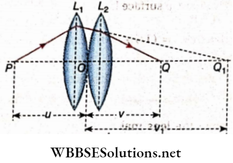
In this case, object distance = OP = -u, image distance
= OQ1 = v1 , focal length =+f1.
⇒ \(\frac{1}{v_1}-\frac{1}{u}=\frac{1}{f_1} \text { or, } \frac{1}{v_1}+\frac{1}{u}=\frac{1}{f_1}\)………………. (1)
Q1 acts as a virtual object concerning the second lens and forms the final real image at Q due to refraction in the second lens L2. So, in this case, object distance = OQ1 = +v1, image distance = OQ = +v, focal length =f1.
⇒ \(\frac{1}{v_1}-\frac{1}{u}=\frac{1}{f_1} \text { or, } \frac{1}{v_1}+\frac{1}{u}=\frac{1}{f_1}\)………………. (2)
Adding equations (1) and (2) we get
⇒ \(\frac{1}{v}+\frac{1}{u}=\frac{1}{f_1}+\frac{1}{f_2}\) ………………. (3)
Now, if the equivalent focal length is F, according to the definition, the equivalent lens will form the image of the equivalent lens will be converging. So we can write
⇒ \(\frac{1}{v}-\frac{1}{-u}=\frac{1}{F} \quad \text { or, } \frac{1}{v}+\frac{1}{u}=\frac{1}{F}\) ………………. (4)
From equations (3) and (4), we get
⇒ \(\frac{1}{F}=\frac{1}{f_1}+\frac{1}{f_2}\) ………………. (5)
If several thin lenses are placed in contact, it can be proved similarly that
⇒ \(\frac{1}{F}=\frac{1}{f_1}+\frac{1}{f_2}+\frac{1}{f_3}\) ………………. (6)
It is to be noted that instead of the combination of convex lenses, a combination of concave lenses or a mixed combination of convex and concave lenses may be used. In each case, equivalent focal length is obtained from equation (6), with proper signs of focal lengths of the lenses used
If an equi-convex lens focal length f is cut vertically into two equal haves, each half will have a focal length equal to 2f.
One of the lenses of the combination is convex and the other is concave:
Let the focal length of the convex lens be /t and that of the concave lens be f2 , If F be the focal length of the combination, then
⇒ \(\frac{1}{F}=\frac{1}{f_1}+\frac{1}{-f_2}=\frac{1}{f_1}-\frac{1}{f_2}\)
∴ \( \frac{f_1 f_2}{f_2-f_1}\)
If f1>f2, then F will be negative and the combination will act as a concave lens. I If f1 < f2 then F will be positive and the combination will act as a convex lens.
[H If f1 = f2, then F will be infinite and the combination will act as a plane laminar plate
The general formula of equivalent focal length:
In all practical purposes, no lens-combination is formed by keeping the lenses in contact. Rather, in different optical Instruments the lenses are necessarily placed separated by a distance. Again, f even when the two lenses are placed in contact, an effective distance due to their thickness is introduced. This distance cannot be ignored in all cases.
Let the focal length of two lenses placed co-axially be f1 and f2 and the distance between their optical centres be a.
Then the expression of the equivalent focal length of the combination of lenses is given by
⇒ \(\frac{1}{F}=\frac{1}{f_1}+\frac{1}{f_2}-\frac{a}{f_1 f_2}\) ………………… (7)
When the two lenses are in contact, a = 0; then equation (7) becomes equation (5).
Refraction Of Light At Spherical Surface Lens Combination Of Lenses And Equivalent Focal Length Numerical Examples
Example 1. A combination of a convex lens of focal length 20 and a concave lens of focal length 10 cm Is formed by keeping In contact with each other. Determine the equivalent focal length of the combination
Solution:
Here, f1 = 20 cm and f2= -10 cm
We know \(\frac{1}{F}=\frac{1}{f_1}+\frac{1}{f_2}\)
⇒ \(\frac{1}{F}=\frac{1}{20}+\frac{1}{-10}=\frac{-1}{20}\)
F = – 20 cm
Since the sign of equivalent focal length is negative, the equivalent lens is concave
Example 2. A lens combination is formed by keeping a lens in contact with a concave lens of a focal length 25 cm. This Icnscomblnatlon produces a real Image magnified 5 tim* of an object placed at a distance of 20 cm from the combination. Calculate the focal length and the nature of the lens placed In contact with the concave lens.
Solution:
Final magnification, m = \(\frac{v}{u}\)
= 5
v = 5u = 100 cm (as u = 20 cm )
From lens formula = \(\frac{1}{v}-\frac{1}{u}=\frac{1}{F}\)
We get, for the combination
⇒ \(\frac{1}{100}-\frac{1}{-20}=\frac{1}{F}\)
∴ u is negative
Or \(\frac{100}{6}\)
= 16.66 cm
For the combination, let the focal length of the unknown lens be f. Then
⇒\(\frac{1}{f}-\frac{1}{25}=\frac{1}{16.66}\)
Or, \(\frac{1}{f}=\frac{1}{16: 66}+\frac{1}{25}\)
The unknown lens is a convex lens with a focal length 10 cm
Refraction Through Spherical Surfaces Physics Notes
Combination Of Lenses And Mirror
Combination of a convex lens and a plane mirror determination of the focal length of a convex lens:
A lane mirror MM’ is placed behind a convex lens LL’
A pin AB is placed in front of the combination of lens and mirror in such a way that the tip of pin A just tousches the principal axis of the lens, The pin is moved until its real Image Ao’ coincides with the pin Itself without parallax, lids Is possible only If the rays from A are Incident normally on the plane mirror after refraction from the lens and these rays retrace the same path.
Then the real Image A’B’ IS formed at the position of All. The tip A of the pin All Indicates the position of the focus of the Ions. So If the lens Is thin, the distance of the tip of the pin from the surface of the lens Is the focal length of the lens. If the lens Is thick, half of the thickness of the lens is to be added to the previous distance to get the focal length of the convex lens.
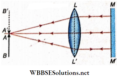
Combination of a convex lens and a convex mirror: Determination of the focal length of a convex mirror:
In LL’ Is a convex lens. The convex mirror MM’ IS placed a little behind the convex lens. Now the point object P is to be placed in front of the combination of lenses and mirror at such a distance that the image of the object coincides with the point object.
It Is possible only if the rays from P are incident normally on the convex mirror after refraction by the lens. These rays if produced further, must converge to the center of curvature C of the mirror. Hence the rays after being reflected from the convex mirror return along the same path and form the image at P.
Now on applying the lens formula for the formation of a real image by a convex lens, the image distance OC is determined. Measuring the distance of the mirror from the lens i.e., OO1, the distance O1C is determined. This distance O1C is the radius of curvature of the convex mirror.
Half of this distance is the focal length of the convex mirror
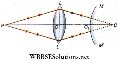
Combination of a convex tens and a concave mirror: Determination of focal; length of a concave mirror:
In LL’ is a convex lens. P is a point object Placed on the principal axis of the lens. MM’ is a concave mirror placed at a certain distance on die other side of the lens. The point object P is placed on the axis; at such a distance that its image coincides with the object at the same point P.
Since the final image coincides with the object at the same point, it can be said that the ray of light after passing through the convex lens is incident on the mirror perpendicularly. So point Q in the figure is the centre of curvature of the concave mirror. On applying the lens formula for the formation of a real image by a convex lens the image distance OQ is determined
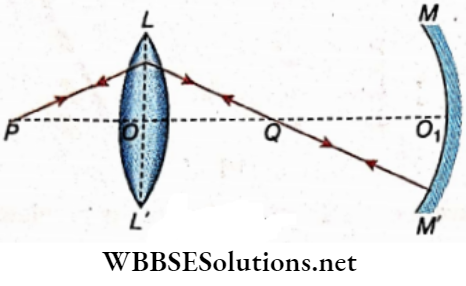
So the radius of curvature of the concave mirror, QO1 = OO1– OQ
If OO1 is known, QO1 can be determined.
Therefore focal length of the concave mirror = \(\frac{1}{2}\) QO1
Combination of a concave lens and a concave mirror: Determination of focal length of a concave lens:
In LL’ is a concave lens. P is a pin. It is taken as a point object placed on the principal axis of the lens. MM’ is a concave mirror placed at a certain distance on the other side of the lens. Now the pin is placed in front of the lens at such a distance that the image formed by the combination of the lens and the mirror will be formed at the position of the pin.
It is possible only if the light rays from the object after refraction by the lens are incident perpendicularly on the concave mirror and after reflection from the mirror return along the same path. In that case, if the lens is absent, the reflected rays would meet at Q, the centre of curvature of the mirror. So concerning the concave mirror, the real image of the virtual object at Q is formed at P.
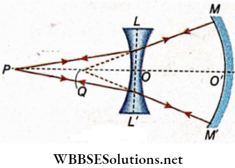
If the radius of curvature of the concave mirror is known, QO’ will be known. Again If the distance between the lens and the mirror i.e., OO’ is known, QO will be known since QO = QO’-OO’ .
This QO is the virtual object distance with respect to the concave Knowing the distance PO and using the general lens for the focal length of the concave lens can be determined.
Refraction through spherical surfaces physics notes
Refraction Of Light At Spherical Surface Lens A Few Problems On Formation Of Real Image By A Convex Lens
Prove that by keeping the object and the screen fixed, a convex lens can be placed in two such positions that in each position, a distinct image of the object is formed on the the screen. Suppose, PQ is an object and S1S2 is a screen In between them a convex lens LL” is placed.
The lens forms a real image pq on the screen. Let the distance between the object and the screen =D, object distance = u, image distance = v. Here, D ‘ = u + v For the formation of a real image by a convex lens the equation of the lens is
⇒ \(\frac{1}{v}+\frac{1}{u}\)=\(\frac{1}{f}\)
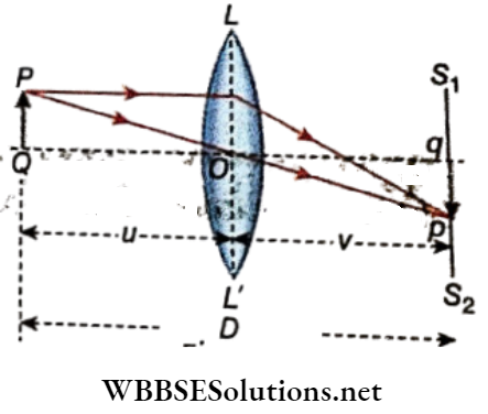
∴ \(\frac{1}{D-u}+\frac{1}{u}=\frac{1}{f}\)
Or, \(\frac{D}{(D-u) u}=\frac{1}{f}\)
Or, u² – Du +Df = 0……………(1)
In solving this equation, the following two values of u are obtained
⇒ \(\begin{aligned}
& u_1=\frac{D+\sqrt{D^2-4 D f}}{2} \\
& u_2=\frac{D-\sqrt{D^2-4 D f}}{2}
\end{aligned}\) Taking u1 > u2 ……………….(2)
For the different values of (D2– 4Df) three cases may arise:
1. When D² > 4Df i.e., D > 4f, the values of u1 and u2 are real and different.
So, if the distance between the object and the screen is greater than 4 times the focal length of the lens, then for two different positions of the lens, two real images of the object are formed on the screen.
2. When D2 = 4Df i.e., D = 4f, the values of u1 and u2 real and equal u1 = u2 = \(\frac{D}{2}\)
So, if the distance between the object and the screen is equal to 4 times the focal length of the lens, then for a single position of the lens, real images of the object are formed on the screen.
In this case, the lens is to be placed in the middle of the object and the screen, because
Object distance = u = u1 = u2 = \(\frac{D}{2}\)
= \(\frac{D}{2}\)
= 2f
And image distance =v = D-u = 4f- 2f = 2f.
3. When D² < 4Df i.e., D < 4f, the values of uy and u2 are imaginary. So in this case, wherever the lens is placed, no image is formed on the screen.
So it is clear from the above discussion that to obtain a real image on a screen with the help of a convex lens, the minimum distance between the object and the screen should be 4 times the focal length of the lens. If the distance between the object and the screen is greater than
4 times the focal of the lens two images will be obtained on-.the screen for two positions of the lens
An object and a screen are placed at a fixed distance D apart from each other. There are two positions for a convex lens in between them for a sharp image to be cast on the screen.
If the separation between positions shows that the focal length of the lens is given by f = \(\frac{D^2-x^2}{4 D}\)
Suppose, OO is the position of the object and SS{ is the position of the screen. L1 and L2 are two different positions of the lens. these two positions of the lens, the image of the object is obtained on the screen,
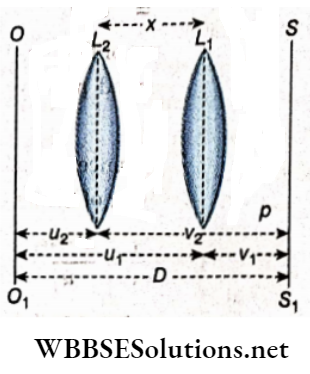
We have seen in the discussion of the problem
u1 = \(\frac{D+\sqrt{D^2-4 D f}}{2}\)
u1 = \(\frac{D-\sqrt{D^2-4 D f}}{2}\)
u1 and u2 have been chosen arbitrarily
u1– u1 = \(\frac{1}{2}\left[\left(D+\sqrt{D^2-4 D f}\right)-\left(D-\sqrt{D^2-4 D f}\right)\right]\)
Or, \(\sqrt{D^2-4 D f}\)
u1– u2 = x = distance between the two positions of the lens]
Or, x2 = D2 – 4Df
or, f = \(\frac{D^2-x^2}{4 D}\)
If two images of the object are obtained on the screen for two different positions of the lens, prove that ux = v2 and Vy = u2.
Suppose, the distance between the object and the screen is D.
For the first position of the lens at L1, object distance = u1 and image distance = v1
For the second position of the lens at L2 the corresponding values are u2 and v2 respectively
u1+ v1 = D and u2+ v2 = D
Taking u1 = \(\frac{D+\sqrt{D^2-4 D f}}{2}\)
And So , u2 = \(\frac{D-\sqrt{D^2-4 D f}}{2}\)
∴ v1 = D – \(D-\frac{D+\sqrt{D^2-4 b f}}{2}=\frac{D-\sqrt{D^2-4 D f}}{2}\) = u2
And v1 = D – \(\frac{D-\sqrt{D^2-4 D f}}{2}=\frac{D+\sqrt{D^2-4 D f}}{2}\) = u1
4. A convex lens is placed between an object and a screen. If dj and d2 be the lengths, of the two real images formed for taro positions of. the lens and d be the length of the object, prove that d = \(\sqrt{d_1 d_2}\)
Suppose, for the first position of the lens the length of the image = d1, and for the second position of the lens the length of the image = d2
If u1 and v1 are the object distance and the Image distance respectively for the first position of the lens, then
Magnification m1 = \(\frac{d_1}{d}=\frac{v_1}{u_1}=\frac{D-u_1}{u_1}\)
[∴ D = u1 +v1 ]
If u2 and v2 are the object distance and the Image distance respectively for the first position of the lens, then
Magnification m2 = \(\frac{d_2}{d}=\frac{v_2}{u_2}=\frac{D-u_2}{u_2}\)
∴ m1 × m2 = \(\frac{d_1}{d} \times \frac{d_2}{d}=\frac{\left(D-u_1\right)\left(D-u_2\right)}{u_1 u_2}\)
∴ \(\frac{d_1 d_2}{d^2}=\frac{D^2-\left(u_1+u_2\right) D+u_1 u_2}{u_1 u_2}\)
= \(\frac{D^2-\left(u_1+v_1\right) D+u_1 u_2}{u_1 u_2}\)
Since u2 = v1
= \(\frac{D^2-D^2+u_1 u_2}{u_1 u_2}\)
Since = u1 +v1 = D
= \(\frac{u_1 u_2}{u_1 u_2}\) = 1
d1 d2 = d² or, d = \(\sqrt{d_1 d_2}\)
i.e., the size or length of the object the geometrical mean of the sizes or lengths of the images formed on screen for two different positions of the lens
5. A convex lens is placed between an object and a screen. A real image of the object is formed for two positions of the lens. If m1 and m2 are the magnifications of the Image for the two positions of the lens respectively, prove that the focal length of the lens is given by f =
\(\frac{x}{m_2-m_1}\) Where x = Distance between the two positions of the lens
According to the position of the lens at L1 object distance = u1 and image distance = v1. For the
Formation of real image by the convex lens at lens the equation of the lens is
⇒ \(\frac{1}{v_1}+\frac{1}{u_1}=\frac{1}{f}\)
Or, \(1+\frac{v_1}{u_1}=\frac{v_1}{f}\)
Or, \(1+m_1=\frac{v_1}{f}\)
Since m1 = \(\frac{v_1}{u_l}\) ……………… (3)
Similarly, for the position of the lens at L, object distance = u2 and image distance – v2 For the formation of a real image by the lens, the equation of the lens is
⇒ \(\frac{1}{v_2}+\frac{1}{u_2}=\frac{1}{f}\)
Or, \(1+\frac{v_2}{u_2}=\frac{v_1}{f}\)
Or, \(1+m_1=\frac{v_1}{f}\)
Since m1 = \(\frac{v_1}{u_l}\) ……………… (4)
Subtracting equation (3) from equation (4) we get,
1 +\(m_2-1-m_1=\frac{v_2}{f}-\frac{v_1}{f}\)
Or, \(m_2-m_1=\frac{v_2-v_1}{f}\)
Or, \(m_2-m_1=\frac{x}{f}\)
Since [v2– v1= u1-u2= x]
Or, f = \(\frac{x}{m_2-m_1}\)
Class 12 physics spherical lens refraction notes
Refraction Of Light At Spherical Surface Lens Displacement Method To Find The Focal Length Of A Convex Lens By Finding Position Of Images
A Convex Lens By Finding Position Of Images Procedure
Two pins N1 And N2 are mounted on the optical bench such that the separation such that the separation between them is greater
then four times the focal length of the convex lens. Now the lens is placed in between the pins N1 and N2 Two positions of the lens are found in such a way that in each position of the lens the image of one pin if formed at the position occupied by the other
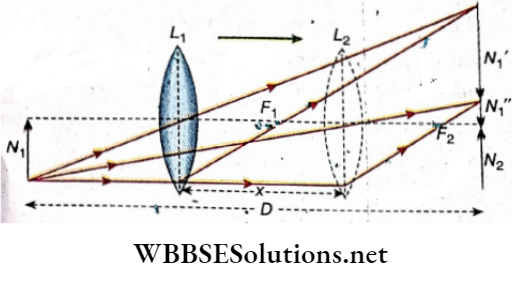
A Convex Lens By Finding Position Of Images Calculation
Let the distance between the two pins be D distance between the two positions of the lens be x. For the first position L1 of the lens,’
u = N1L1 = \(\frac{1}{2}\left(N_1 N_2-L_1 \dot{L}_2\right)=\frac{1}{2}(D-x)\)
v = L1N2 = \(N_1 N_2-N_1 L_1=D-\frac{1}{2}(D-x)=\frac{1}{2}(D+x)\)
The general formula of a convex lens forming a real image is
⇒ \(\frac{1}{v}+\frac{1}{u}=\frac{1}{f}\)
⇒ \(\frac{2}{D+x}+\frac{2}{D-x}=\frac{1}{f}\)
Or, \(\frac{1}{f}=\frac{4 D}{D^2-x^2}\)
Or, f = \(\frac{D^2-x^2}{4 D}\)
Measuring D and x from the optical bench, the focal length of a convex lens can be determined from equation (1)
Refraction Of Light At Spherical Surface Lens Power Of A Lens
The function of a lens is to converge a beam of light in the case of a convex lens or to diverge it in the case of a concave lens
Power of a Lens Definition
The power of a lens is the degree of convergence in the case of the convex lens or the degree of divergence in the case of a concave lens.
Since a convex lens of shorter focal length produces a greater convergence and a concave lens of shorter focal length produces
Hence, the reciprocal of the focal length of a lens is called its power. Representing the fatal length of a lens by f and power by P we can write, P = \(\frac{1}{f}\)
Unit of power of lens
The unit of power of the lens is dioptre (dpt or, D).
1 dioptre is defined as the power of a lens of focal length one meter. So unit of power oflens in SI is m-1
i. e P = \(\frac{1}{\text { focal length in meter }} \text { dioptre or } \mathrm{m}^{-1}\)
= \(\frac{100}{\text { focal length in centimeter }} \text { dioptre or } \mathrm{m}^{-1}\)
or, p (diopter) = \(\frac{1}{f(\text { metre })}=\frac{100}{f(\text { centimetre })}\)
The power of a convex lens is considered positive and that of a concave lens is considered negative.
The convex lens having a focal length of 20 cm has power
= \(\frac{100}{20}\)
= 5 dpt
The lens having power 4 dpt has a focal length
= \(\frac{1}{4}\) m = 25 cm
Again, the nature of the lens having power -4 dioptre is concave, and its focal length
f = \(\frac{1}{4}\) = – 0.25m
Power of a combination of lenses
The power of; a combination of lenses is equal to the algebraic sum of the powers of the constituent lenses.
The power of the combination of two lenses with powers Px and P2 kept in contact with one another is
p = P1+P2
Relation of the radius of curvature of a lens with the power
We know that the equation of focal length of a given by,
⇒ \(\frac{1}{f}=(\mu-1)\left(\frac{1}{r_1}-\frac{1}{r_2}\right)\)
If the radii of curvature of the two surfaces of the lens be equation then in the case of biconvex and biconcave lenses we have,
⇒ \(\frac{1}{f}=(\mu-1) \cdot \frac{2}{r}\) and
⇒ \(\frac{1}{f}=-(\mu-1) \frac{2}{r}\) respectively
So, the corresponding power of (these lenses are,
P = (mu-1).\(\frac{2}{r}\) and p = -(mu-1)
I. e \(P \propto \frac{1}{r}\)
Therefore, if the radius of curvature of a biconvex or a biconcave lens increases, the power of the lens decreases, and if the radius of curvature decreases power of the lens increases.
1. When two thin lenses haying equal and opposite focal lengths (one convex and one concave) are placed in contact with each other and if F be their equivalent focal length then
⇒ \(\frac{1}{F}=\frac{1}{f}+\frac{1}{-f}\) = 0
F = \(\frac{1}{0}\)
So, power P = \(\frac{1}{F}\) = 0
This type of combination of lenses acts as a plane glass plate.
2. If the refractive index of the medium surrounding the lens is greater than that of the material of the lens, the convex lens shows diverging power and the concave lens shows converging power
3. Suppose that the refractive index of the surrounding medium is μm and the refractive index of the material of the lens is μg. If μm increases, the power of the lens decreases i.e, its focal length increases
Change of the focal length and the power of a lens with the wavelength of the incident light:
According to Scientist Cauchy, the relation of wavelength (λ) with refractive index (μ) is given by
μ = A + \(\frac{B}{\lambda^2}\) [ where A and B are constants]
Now, if be the focal length of a lens then,
⇒ \(\frac{1}{f}=(\mu-1)\left(\frac{1}{r_1}-\frac{1}{r_2}\right)\)
So, for any particular lens,
⇒ \(f \propto \frac{1}{(\mu-1)}\)
In comparison to any other wavelength of light, the wavelength of red light is greater i.e., for red light, the refractive index of the lens is minimal. So the focal length of a lens is greater for red light is comparison to other colours.
The power of a lens is given by
⇒ \(P\frac{1}{f}=(\mu-1)\left(\frac{1}{r_1}-\frac{1}{r_2}\right)\)
Or, P ∝(μ-1)
So, the power of a lens will be less in the case of red light in comparison to any other colour.
f-number of lens:
The focal length of a lens is generally expressed as a multiple of the diameters of its aperture. This multiple is called the f-number of lenses. If F is the focal length and D is the diameter of the aperture, Then D = \(\frac{F}{f}\) or, f = \(\frac{F}{D}\). For example, if the f-number of a lens is (\(\frac{1}{15}\)), it means that the diameter of the aperture of the lens is its focal length.
Depth of field:
In optics, depth of field (DOF) is the distance between the nearest and farthest objects in a scene that appear acceptably sharp in an image. The term mainly relates to film and photography. For a particular lens greater the value of f-number, the greater is the depth of field.
Class 12 physics spherical lens refraction notes
Refraction Of Light At Spherical Surface Lens Power Of A Lens Numerical Examples
Example 1. The power of a lens- of a pair of spectacles is -2.5 dioptre. What is the nature and focal length of the lens used?
Solution:
We know, P= + \(\frac{100}{f}\)
⇒ \(\frac{100}{f}\) dioptre
[If f is expressed in cm]
= – 2.5 = + \(\frac{100}{f}\) Or, f = -40 cm
Since the focal length is negative, the lens is concave and its focal length is 40 cm.
Example 2. A lens of power 0.5 dioptre is placed In front of a lens of power 2.0 dioptre. Assume that the distance between the two lenses is zero,
- What will be the power of the lenses in dioptre
- What will be their focal lengths?
Solution:
Power of the combination of lenses
P = P1 + p2
Here P1 = 0.5 dpt
P2 = 2 dpt
= 0. 5 + 2 = 2.5 dpt = 2.5 m–1
The focal length of the lens of power is 0.5 dioptre
f1 = \(\frac{+100}{0.5}\) = 200 cm (convex lens)
And focal length of the lens of power 2.0 dpt
f2 = \(\frac{100}{2}\)
= + 50 cm (convex lens)
Example 3. A convex lens of focal length 40cm Is placed In contact with a concave lens of focal length 25cm. What Is the power of the lens combination?
Solution:
Power of the convex lens, P2 = \(\frac{100}{f_1}\)
⇒ \(\frac{100}{40}\) ‘
Power of the concave Mirror lens P2 = \(\frac{100}{f_2}=\frac{100}{-25}\) = -4.0 m–1
= 2.5 m–1
The Power of the combination of lenses
P = P1+P2 = 2.5 – 4.0 = -1.5 m–1
Example 4. An object is placed at a distance of 12 cm from a lens and a virtual image, four times magnified is formed. Calculate the focal length of the lens. Draw the ray diagram for the formation of linage. What Is the power of the lens?
Solution:
Magnification , m= \(\frac{v}{u}\) = 4 or, v = 4u
From diagram u = OQ = -12 cm, v = OQ’ = -48 cm

From the lens equation
⇒ \(\frac{1}{f}=\frac{1}{v}-\frac{1}{u}=\frac{1}{-48}-\frac{1}{-12}\)
Or, \(\frac{1}{f}=\frac{1}{12}-\frac{1}{48}\)
Or, f = 16
The focal length of the lens is 16 cm.
The lens is convex i.e.,f is positive.
Power of the lens P = \(\frac{100}{f}\) D = \(\frac{100}{16}\) D
= + 6.25 D
Example 5. A real image of an object Is formed by a convex. lens on. a screen at a distance of 20 cm from the lens. When a concave lens is placed at a distance of 5 cm from the convex lens towards the screen the Image Is shifted through 10 cm. Calculate the focal length and the power of the concave lens.
Solution:
The role of the convex lens is just to form the first image on the screen
For the concave lens, this image acts as the virtual object, and another real image is formed at a distance of 10 cm away from The virtual object.
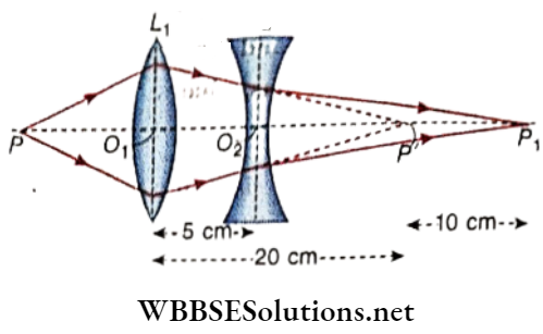
Let P is the position of the object. L1 and L2 are the convex and concave lenses respectively separated by O1O2= 5 cm
P’ is the real image formed by L1 and O1P’ = 20 cm
P’ acts as the virtual object for the second lens L2 and a real
Image of P’ is formed at P1, the distance P’P1 = 10 cm
∴ For the concave lens:
u = O2P’ = O1P’- O1O2 = 20 – 5 = 15 cm
And v = O2P1 = O2P’ + P’P1 = 15 + 10 = 25 cm
Putting in \(\frac{1}{v}-\frac{1}{u}=\frac{1}{f}\), we get
⇒ \(\frac{1}{25}-\frac{1}{15}=\frac{1}{f}\),Or, f = – 37. 5 cm
So, the focal length of the concave lens is 37.5 cm
Power of the lens = \(\frac{100}{f}=\frac{100}{-37.5}\)D
= – 2.67 D
Class 12 Physics Spherical Lens Refraction Notes
Example 6. The distance between a lamp and a screen is 90 cm. Where should a convex lens of focal length 20 cm be placed between the lamp and the screen so that a real Image of the lamp Is formed on the screen?
Solution:
Let the distance of the lamp from the lens be x cm.
So, image distance =(90-x) cm I.e., u = -x and v = (90-x)
For the formation of a real image by the convex lens we have
⇒ \(\frac{1}{v}-\frac{1}{u}=\frac{1}{f}\)
Or, \(\frac{1}{90-x}+\frac{1}{x}=\frac{1}{20}\)
Or, \(\frac{90}{x(90-x)}=\frac{1}{20}\)
Or, x² – 90x +1800 = 0
Or, (x – 30)(x – 60)= 0
Or, x = 30 cm or, 60 cm
So, the lens is to be placed at a distance of 30 cm or 60 cm concerning the lamp.
Example 7. The size of the image of an object that is at infinity, as formed by a convex lens of focal length 30 cm, is 2 cm. If a concave lens of focal length 20 cm is placed between the convex lens and the image at a distance of 26 cm from the convex lens what will be the size of the final image?
Solution:
For the convex lens, since the object is at Infinity
Image is formed at the focus (P’)
∴ v = f = 30 cm
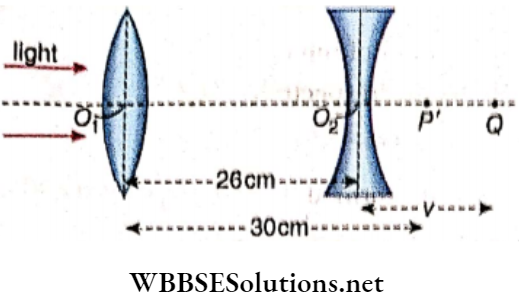
This is the virtual object for the second lens which Is at a distance Oj02 = 26 cm from the first lens.
In this case object distance
u = (O1P’-O1O1) = 30 -26 = 4cm and f = -20 cm
⇒ \(\frac{1}{v}-\frac{1}{4}=\frac{1}{-20}\) Or, + = 5 cm
Magnification by the second lens = \(\frac{5}{4}\)
Size of the final image = size of the 1st image x \(\frac{5}{4}\)
= 2 × \(\frac{5}{4}\)
= 2.5 cm
Example 8. The image of an Illuminated pin placed at a distance of 20 cm from a convex lens is formed on a screen placed at a distance of 30 cm from the lens. Between the screen and the convex lens, a concave lens is placed at a distance of 10 cm from the convex lens. If the screen Is shifted through a distance of 10 cm more, a distinct image is formed on the screen. Find the ratio of the power of the two lenses. If the power of the concave lens Is -4 m-1, how far should the screen is to be shifted?
Solution:
For the convex lens
u = O1 P = -20 cm
v = O1P = 30 cm , f= ?
From \(\frac{1}{v}-\frac{1}{u}=\frac{1}{f}\) we ,get
⇒ \(\frac{1}{30}-\frac{2}{-20}=\frac{1}{f_1}\)
Let the focal length be f1
∴ f1 = 12cm
Example 9. The radii of the curvature of (lie two surfaces of a convexoconcave lens made of glass are 20 cm and 60 cm. An object Is situated on the left side of the lens at a distance of 80 cm along the principal axis.
- Determine the position of the Image
- A similar type of lens Is placed at a u distance of 100 cm on the right side of the first lens co-axially Determine the position of the image. [Given mu of glass a l.5 ]
Solution: The focal length of an Ions Is given the lens maker’s formula
⇒ \(\frac{1}{f}=(\mu-1)\left(\frac{1}{r_1}-\frac{1}{r_2}\right)\)
In this case mu = 1.5 r1 = + 20 cm
r1 = + 60 cm
⇒ \(\frac{1}{f}=(1.5-1)\left(\frac{1}{20}-\frac{1}{60}\right)\)
Or, f = 60 cm
Here, u = -80 cm , f = 60 cm
From \(\frac{1}{v}-\frac{1}{u}=\frac{1}{f}\) we get
⇒ \(\frac{1}{v}+\frac{1}{80}=\frac{1}{60}\) or, v = 240 cm
So, the Image Is at a distance of 240 cm on the other side of the lens.
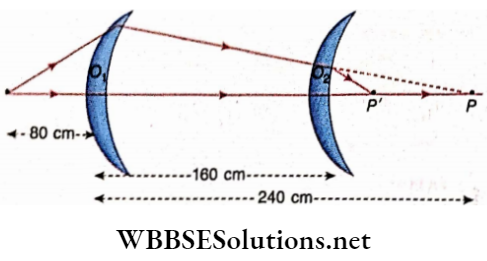
The image P formed by the 1st lens will act as the virtual
Image of the second lens
∴ Object distance, u’ = O2P = 240-160 = 80 cm
Distance is measured along the direction of the ray
And f’ = 60 cm
∴ From \(\frac{1}{v}-\frac{1}{u}=\frac{1}{f}\)
We get, \(\frac{1}{v}-\frac{1}{80}=\frac{1}{60}\)
Or, v = \(\frac{240}{7}\)
= 34.28
So, the final image is formed at a distance of 34.28 cm from the second lens and on the other side of the first lens
Example 10. An illuminated object is placed at a distance 15cm in front of a convex lens of a focal length of 12cm. If a plain mirror is placed behind the lens at a distance 45cm, a distinct image is formed in front of the lens (on the object side) on the screen. Find the distance of the screen from the lens.
Solution:
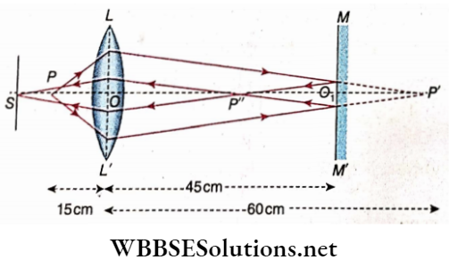
LL’ is a convex lens and MM’ is a plain mirror placed at a distance of 45cm from the lens. P is an illuminated object at a distance 15cm in front of the convex lens.
In the case of image formation by the lens,
u = -15 cm , f= 12 cm, v= ?
From the lens equation,
⇒ \(\frac{1}{v}-\frac{1}{u}=\frac{1}{f}\)
Or, \(\frac{1}{v}+\frac{1}{15}=\frac{1}{12}\)
Or, \(\frac{1}{12}-\frac{1}{15}=\frac{1}{60}\)
∴ v = 60 cm
If the plain mirror is absent a real image will be formed at P’. This P’ will act as a virtual object for the plain mirror.
For plain mirror,
object distance = O1 P’ = 60 – 45 = 15cm
Mirror MM’ will form a real image of P’ at P”.
Now, image P” acts as an object for the formation of the image in a second time
So, object distance – OP”= OO1– O1P”
= (45 – 15) = 30 cm
Since [ O1p’ = O1 P” = 15 cm]
Thus, u = -30cm, f = 12cm, v = ?
From lens equation, \(\frac{1}{v} \cdot \frac{1}{u}=\frac{1}{f}\)
Or, \(\frac{1}{v}+\frac{1}{30}=\frac{1}{12}\) Or, \(\frac{1}{v}=\frac{1}{12}-\frac{1}{30}=\frac{1}{20}\)
Or, v = 20 cm
Therefore an image will be formed on screen S at a distance of 20cm in front of the lens (on the object side).
Example 11. If an object is placed at a distance from a convex lens, the magnification of the real image so formed is m1. If the object is shifted through a distance x, the magnification of the real image now formed is m2. Prove that the focal length of the lens, f = \(\frac{x}{\frac{1}{m_2}-\frac{1}{m_1}}\)
Solution:
Let the object distance and image distance in the first and second cases be u1, v1 and u2, v2 respectively
∴ m1 = \(\frac{v_1}{u_1}\)
And m2 = \(\frac{v_2}{u_2}\)
From the general lens formula, we get
⇒ \(\frac{1}{v}-\frac{1}{u}=\frac{1}{f}\)
Or, \(\frac{u}{v}-1=\frac{u}{f}\)
So in the 1st case, for the formation of a real image in the convex lens
⇒ \(\frac{1}{v_1}+\frac{1}{u_1}=\frac{1}{f} \text { or, } \frac{u_1}{v_1}+1=\frac{u_1}{f}\)
Or, \(\frac{1}{m_1}+1=\frac{u_1}{f}\) ………………… (1)
And the second case, the relationship will be
⇒ \(\frac{1}{v_2}+\frac{1}{u_2}=\frac{1}{f} \text { or } \frac{u_2}{v_2}+1=\frac{u_2}{f}\)
From equations (1) and (2) we get
⇒ \(\frac{u_2}{f}-\frac{u_1}{f}=\frac{1}{m_2}-\frac{1}{m_1}\)…………. (2)
Or, \(\frac{u_2-u_1}{\frac{1}{m_2}-\frac{1}{m_1}}=\frac{x}{\frac{1}{m_2}-\frac{1}{m_1}}\)
Since [ u2 – u2= x]
Class 12 physics spherical lens refraction notes
Example 12. An Object Is Placed At A Distance D From A Screen. A Convex Lens Forms A Distinct Image of Object On The Screen. When The Lens Is Shifted Through A Distance X Towards The Screen, Another Distinct Image Is Formed Cm The Screen. Prove That The Ratio Of The Lizes Of The first and the second images are equal to \(\left(\frac{D+x}{D-x}\right)\)
Solution:
Suppose, in the first case, object distance -u, image distance =D
For the formation of a real image in a convex lens, the lens equation is
⇒ \(\frac{1}{v}+\frac{1}{u}=\frac{1}{f} \text { or, } \frac{1}{D-u}+\frac{1}{u}=\frac{1}{f}\)
Or, \(\frac{D}{(D-u) u}=\frac{1}{f}\)
or, u²- Du+Df = 0
The two roots of u are
u1 = \(\frac{D-\sqrt{D^2-4 D f}}{2}\)
And u2 = \(\frac{D+\sqrt{D^2-4 D f}}{2}\) …………….. (1)
According to the
x = u2– u1
⇒ \(\frac{D+\sqrt{D^2-4 D f}}{2}-\frac{D-\sqrt{D^2-4 D f}}{2}\)
⇒ \(\sqrt{D^2-4 D f}\)
Putting the value of x in equation (1) we get
u1 = \(\frac{D-x}{2}\) and
u2 = \(\frac{D+x}{2}\)
Let v1 and v2 be the image distances corresponding to the object distances Uj and u2 respectively.
v = D-u = \(-\frac{D-x}{2}=\frac{D+x}{2}\) and
v = D-u = \(-\frac{D+x}{2}=\frac{D-x}{2}\)
⇒ If f be the size of the object and I1 had I2 be the size of the images for the two positions of the lens, then
⇒ \(\frac{I_1}{I}=\frac{v_1}{u_1}=\frac{D+x}{D-x}\)
And \(\frac{I_2}{I}=\frac{v_2}{u_2}=\frac{D-x}{D+x}\)
⇒ \(\frac{I_1}{I_2}=\frac{\frac{1}{I}}{I_2}=\frac{\frac{D+x}{D-x}}{\frac{D-x}{D+x}}\)
= \(\left(\frac{D+x}{D-x}\right)^2\)
Example 13. The focal length of a lens is inversely proportional to, (n-1) where n is the refractive index. Forviolet light if the focal length of the lens is 50 mm, what will be the focal length of the lens for red light? Given for violet light, n = 1.532 andforred light, n = 1.512.
Solution:
If f is the focal, the length of the lens
⇒ \(f \propto \frac{1}{n-1}\)
or, f = \(\frac{k}{n-1}\)
⇒ \(-\frac{f_r}{f_\nu}=\frac{n_\nu-1}{n_r-1}\)
⇒ \(f_r=\frac{n_\nu-1}{n_r-1} \times f_\nu\)
= \(\frac{1.532-1}{1.512-1} \times 50\)mm
= 51.95mm
So, the focal length of the lens for red light is 51.95 mm.
Example 14. The focal length–of the lens of a camera is 1.25 times its I diameter. Calculate the angle of deviation of a ray parallel to the axis of the lens incident at the edge of the lens.
Solution:
Suppose, the diameter of the lens is D and the focal length of the lens is f.
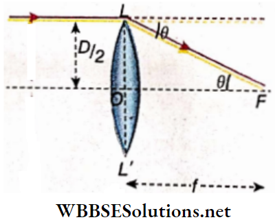
According to the question, f = 1.25D.
According to suppose that the ray has deviated through an angle θ
⇒ \(\tan \theta=\frac{O L}{O F}=\frac{\frac{D}{2}}{f}\)
⇒ \(\frac{D}{2 f}=\frac{D}{2 \times 1.25 D}\)
Or, tan θ \(\frac{1}{2.5}\)
= 0.40
= tan 22°
or, θ = 22°
Example 15. Two lenses one convex and another, concave, both of equal focal length are placed In contact What is the focal length of the lens combination?
Solution:
If F is the equivalent focal length of the lens combination, then
⇒ \(\frac{1}{F}=\frac{1}{f_1}+\frac{1}{f_2}\)
For convex lens, f1 = f and for concave lens, f2 = -f
Thus \(\frac{1}{F}=\frac{1}{f}-\frac{1}{f}\) = 0 Or, F = ∞
Therefore, the focal length of the lens combination will be infinite,
Example 16. A convex lens of focal length 15 cm is placed coaxially at a distance of 5 cm in front of a convex mirror. When an object is placed on the axis at a distance of 20 cm from the lens, it is found that the image coincides with the object. Find the focal length of the mirror.
Solution:
Here, the object at P is supposed to be a point object. LL’ is the convex lens and MM’ is a convex mirror. If the image of the object is to coincide with the point object, the light rays after being refracted from the lens must be incident normally on the convex mirror i.e., the light rays should be directed along the radius of curvature, C of the convex mirror as a result of which after being reflected on the mirror the rays of light return along the same path and form image at P.

According to the problem, u = -20 cm, f = 15, v =?
According to the equation of lens,
⇒ \(\frac{1}{v}-\frac{1}{u}=\frac{1}{f} \text { or, } \frac{1}{v}=\frac{1}{u}+\frac{1}{f}\)
Or, \(\frac{1}{v}=\frac{1}{-20}+\frac{1}{+15}=+\frac{1}{60}\)
Or, v = + 60 cm
OC = 60 cm
Or, OO1+O1C = 60
Or, 5 + O1 C = 60 Or, O1C = 55
∴ The radius of curvature of the convex mirror = 55 cm
∴ Focal length = \(\frac{55}{2}\) = 27.5 cm
Class 12 physics spherical lens refraction notes
Example 17. if an object is placed at position A in front of a convex of vex lens of focal length f, the Image produced by the lens becomes erect But If the object Is placed at position B, an Inverted image of the same size is produced. If the amount of magnification is m, prove that AB = \(\frac{2 f}{m}\)
Solution:
In the 1st case, let the object distance, OA = u1 and image distance, OA1 = v1
From the lens equation, we get,
⇒\(\frac{1}{-\nu_1}-\frac{1}{-u_1}=\frac{1}{f}\)
Or, \(-\frac{u_1}{v_1}+1=\frac{u_1}{f}\) ……………………. (1)
In this case, magnification, m = \(\frac{\nu_1}{u_1}\)
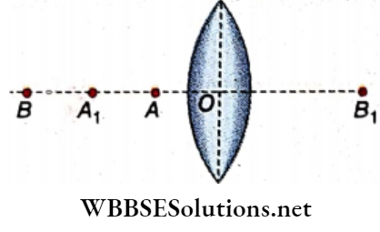
Putting in equation (1) we get
⇒ \(-\frac{1}{m}+1=\frac{u_1}{f}\)
Or, \(\frac{1}{m}-1=-\frac{u_1}{f}\) …………………………….. (2)
Similarly, in the second case, let the object distance, OB1 = u2, and image distance, OB1 = v2
In this case, magnification
⇒ \(\frac{1}{v_2}-\frac{1}{-u_2}=\frac{1}{f}\)
Or, \(\frac{u_2}{v_2}+1=\frac{u_2}{f}\)
Or, \(\frac{1}{m}+1=\frac{u_2}{f}\)
Or, \(\frac{1}{m}+1=\frac{u_2}{f}\) ………………………… (3)
From Equations (2) we get
⇒ \(\frac{2}{m}=\frac{u_2-u_1}{f}\)
Or, \(\frac{A B}{f}=\frac{2}{m} \text { or, } A B=\frac{2 f}{m}\)
Example 18. A convex lens of focal length 10cm is placed In front of a concave mirror. The principal axes of both coincide and the lens is at a distance 40cm from the pole of the mirror. If an object is placed on the axis at a distance15 of cm from the lens on another side of the lens, then image point coincides with the object point. Find the focal length of the mirror.
Solution:

LL’ is a convex lens and MM’ is a concave mirror. P is an
object and Q is the image of P formed by the lens.
Here, object distance = PO = u = -15cm
And image distance – OQ = v
From the lens equation, \(\)
⇒ \(\frac{1}{v}-\frac{1}{u}=\frac{1}{f}\)
Or, \(\frac{1}{v}+\frac{1}{15}=\frac{1}{10}\)
Or, v = 30 cm
v is positive Le., the image is formed on another side at a distance of 30cm from the lens. This image acts as a real object for the concave mirror. In this case object distance = O1Q = 40- 30 = 10cm.
Since the final image is formed at the same point where the object is situated it can be concluded that light ray is incident on the mirror normally.
Therefore, Q is the centre of curvature of the concave mirror.
∴ The radius of curvature of the mirror, r = O1Q = 10cm
∴ Focal length of the mirror f = \(\frac{r}{2}=\frac{10}{2}\)
= 5cm
Example 19. The focal length of a convex lens is/ and the distance of the object from the lens is u. A plane mirror is placed perpendicular to the principal axis of the lens at a distance f from the lens on the opposite side of the object. If the final Image is formed at a distance v in front of the lens, prove that u + v= 2f
Solution:
Let P be the object in front of the lens L
Object distance, OP = -u
In the absence of the mirror, P’ would be the image formed by the lens.
Let OP’ = v’
But the rays before forming the image P’ are incident on the mirror M and are reflected by it to form a real image at P” for the virtual object P’.
MP’ = OP’- OM and MP” = MP’
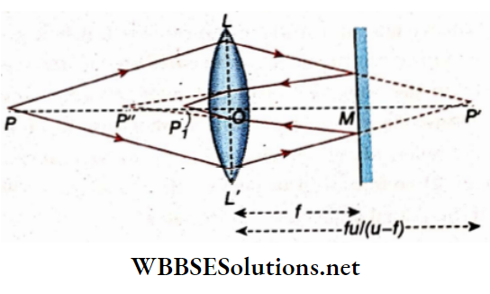
Again the rays before reaching P” are refracted by the lens for the second time and converge at P to form a real image.
Now, OPl = v; OP” = us = MP”-MO
[ u’ is positive as the distance is taken along the direction of the ray.]
Now, for the 1st refraction, we have
⇒ \(\frac{1}{v^{\prime}}+\frac{1}{u}=\frac{1}{f}\)
Or, \(v^{\prime}=\frac{u f}{u-f}\)…………………….. (1)
For reflection in the mirror,
MP’ = \(v^{\prime}-f=\frac{u f}{u-f}-f=\frac{f^2}{u-f}\) ………………………………………… (2)
And MP’ = \(M P^{\prime}=\frac{f^2}{u-f}\)
[Positive, since the distance is taken along the ray]
For the second refraction in the lens
u’ = OP” = MP”- MO
⇒ \(\frac{f^2}{u-f}-f=\frac{2 f^2-u f}{u-f}=\frac{f(2 f-u)}{u-f}\)
From the lens equation; we can write
⇒ \(\frac{1}{v}-\frac{1}{u^{\prime}}=\frac{1}{f}\)
Or, \(\frac{1}{v}-\frac{u-f}{f(2 f-u)}=\frac{1}{f}\)
Or, \(\frac{1}{v}=\frac{1}{f}+\frac{u-f u}{f(2 f-u)}\)
Or, \(\frac{1}{v}=\frac{1}{2 f-u}\)
v = 2f- u
Or, u+v = 2f
Example 20. A Concave of focal length 20 cm Is placed at a distance of 25 cm behind a concave lens. If a pin is u = distance 68.6 cm, placed In front of the lens at an Image formed by the combination of lens and mirror will be formed at the position of the pin. What Is the focal length of the lens?
Solution:
In P is a pin. It is taken as a point object. LL’ is the concave lens and MM’ is the concave mirror. Light rays from the object after refraction in the lens are incident perpendicularly on the concave mirror and after reflection from the mirror return, along the same path. In that case, if the lens is absent the. reflected rays would meet at Q, the optical center of the mirror. Therefore, with respect to the concave lens, the real image of the virtual object at Q is formed at P.
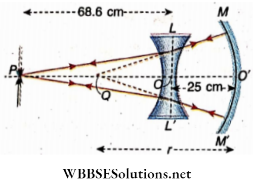
The radius of curvature of the concave mirror,
r = 2f = 2 × 20 = 40 cm
Therefore, concerning the concave lens,
u = OQ =(40-25) = 15 cm
[Along the direction of the ray]
v = 68.6 cm ; f = ?
According to the equation of the lens
⇒ \(\frac{1}{v}-\frac{1}{u}=\frac{1}{f}\)
⇒ \(\frac{1}{68.6}-\frac{1}{15}=\frac{1}{f}\)
Or, \(\frac{15-68.6}{68.6 \times 15}=\frac{1}{f}\)
Or, \(\frac{-53.6}{68.6 \times 15}=\frac{1}{f}\)
Or, f = \(-\frac{68.6 \times 15}{53.6}\)
= 19.2 cm
Therefore, the focal length of the concave lens is 19,2 cm
Example 21. A convex lens of power 5 D is placed on a plane mirror. A pin is placed above 30 cm straight from the lens. Determine the position of the Image. Where should the pin be placed The image will coincide with the pin
Solution:
We know,
P = \(\frac{100}{f}\)
Or, 5 = \(\frac{100}{f}\)
Or, 20 cm
In the case of the formation of an image by the convex lens,
u = -30 cm , f = +20 cm; v = ?
According to the equation of lens
⇒ \(\frac{1}{v}-\frac{1}{u}=\frac{1}{f}\)
⇒ \(\frac{1}{v}-\frac{1}{-30}=+\frac{1}{20}\)
Or, \(\frac{1}{v}=\frac{-1}{30}+\frac{1}{20}=\frac{+1}{60}\)
Or, + 60 cm
So the image is real and is formed at a distance of 60 the lens. This image will act as a virtual object for the plane mirror. The image of this virtual object will be formed above at a distance of 60 cm. This image will again act as a virtual object for the convex lens.
In the case of the formation of an image again by the convex lens,
u = + 60 cm [distance taken along the direction of ray]
f = +20 cm; v = ?
According to the equation of lens,
⇒ \(\frac{1}{v}-\frac{1}{u}=\frac{1}{f}\)
⇒ \(\frac{1}{v}-\frac{1}{60}=\frac{1}{20}\)
Or, \(\frac{1}{v}=\frac{1}{60}+\frac{1}{20}=\frac{1}{15}\)
Or, v = 15 cm
So, the image will be formed above the lens at a distance of
Radius of curvature of the concave mirror, If the pin is placed at the focus of the convex lens, its image will coincide with the pin. In that case the distance of the pin from the lens = 20 cm.
WBCHSE Physics Class 12 Refraction Lens Notes
Example 22. The diameter of the sun makes an angle of 0.5° at the pole of the convex lens. If the focal length of the lens be 1 m, what will be the Image of the sun?
Solution:
Suppose, the diameter of the sun = D m and the distance of the sun from the lens = u m
Angle made by the sun at the pole of the lens, θ = \(\frac{D}{u}\)
Given = 0.5 = \(\frac{0.5 \times \pi}{180}\)rad
As the sun is stated at a long distance, its image is formed at the focus.
v = f
Suppose, the diameter of the image of the sun = d
m = \(\frac{v}{u}=\frac{d}{D}\)
Or, d = \(\frac{v D}{u}\)
fθ = \(\frac{1 \times 0.5 \pi}{180}\)
= 0.00872 m
= 0.872cm
Example 23. There is a square hole In the screen. The hole is Illuminated and its Image is formed on another screen with the help of a convex lens. The distance of the hole from the lens is 40 cm. If the area of the Image is 9 times the area of the hole, determine the position’ of the image and the focal length of the lens.
Solution:
Suppose, the length of each side of the hole = x and the length of each side of the image = y
The area of the hole = x² and the area of the image = y².
⇒ \(\frac{y^2}{x^2}\) = 9
Or, \(\frac{y}{x}\) = 3
m = 3
Or, \(\frac{v}{u}\) = 3 or, 3u = 3 × 40= 120 cm
u = 40 cm
So, the image is formed at a distance of 120 cm from the lens
v = +120 cm and given , u= – 40 cm
According to the equation of lens
⇒ \(\frac{1}{v}-\frac{1}{u}=\frac{1}{f}\)
Or, \(\frac{1}{+120}-\frac{1}{-40}=\frac{1}{f}\)
Or, \(\frac{1}{f}=+\frac{1}{30}\)
f = 30 cm
Therefore, the focal length of the lens is 30 cm
Example 24. The focal—length of a camera lens is 45 cm msmmand the measurement of the photographic plate Is 30 cm x 30 cm. What is the measure of square area of the earth that can be photographed from a plane at a height 1500 m above the earth
Solution:
Here, u = 1500 m = 150000 cm . The image of a very distant object is formed at the focus of the convex lens.
v = f = 45 cm
Now m = \(\frac{45}{150000}\)
Or, \(\frac{\text { length of the image }}{\text { length of the object }}=\frac{45}{150000}\)
Or, length of the object = \(\frac{150000}{45}\) × length of the image
The length of the photographic plate is 30 cm. So, the length of a side of the image of a square area of the earth to be photo-‘ graphed is 30 cm
Length of the square area of the earth
= \(\frac{150000}{45} \times 30\)
= 10000 cm = 1000 m = 1 km
So, the area of the earth to be photographed = 1 km ×1 km = 1 km²
Example 25. The distance of a source of light from a screen Is 1 m. By placing a convex lens between them an image Is cast on the screen. The lens Is shifted through a distance of 40 cm along the line joining the source and the screen and again an Image Is formed on the screen. What is the focal length of the lens? If the length of the images are 0.428 cm and 2.328 cm respectively, what is the length of the object?
Solution:
Distance between the object and the screen, D = lm = 100 cm, and distance between the two positions of the lens, x = 40 cm
If the focal length of the lens
f = \(\frac{D^2-x^2}{4 D}=\frac{(100)^2-(40)^2}{4 \times 100}\)
= \(\frac{140 \times 60}{4 \times 100}\)
= 21 cm
The length of the two images
I = 0.428 cm and J2 = 2.328 cm
Length of the object = \(\sqrt{I_1 I_2}=\sqrt{0.428 \times 2.328}\)
= 0.998 cm
Example 26. Two equal-convex lenses are so placed inside the two curved faces of a thin box of glass that they are well set in the box. The focal lengths of the two lenses are 10 cm and 20 cm respectively. If the box Is used as a lens by filling it with water, how far should the object be placed to get an image double its size? \(\frac{3}{2}\) and uw = \(\frac{3}{2}\)
Solution:
The lens combination has been shown. If the radii of curvature of the two lenses be and r2 , then
⇒ \(\frac{1}{f_1}=(\mu-1) \cdot \frac{2}{r_1}\)
And \(\frac{1}{f_2}=(\mu-1) \cdot \frac{2}{r_2}\)
⇒ \(\frac{1}{10}=\left(\frac{3}{2}-1\right) \cdot \frac{2}{r_1}\)
And \(\frac{1}{20}=\left(\frac{3}{2}-1\right) \cdot \frac{2}{r_2}\)
Or, = r1 = 10 cm and r = 20 cm
If f3 be the focal length of the biconcave lens’ made of water, then
⇒ \(\frac{1}{f_3}=-\left(\mu^{\prime}-1\right)\left(\frac{1}{r_1}+\frac{1}{1+m_2}\right)^{\prime}\)
⇒ \(-\left(\frac{4}{3}-1\right)\left(\frac{1}{10}+\frac{1}{20}\right)=\frac{-1}{3} \times \frac{3}{20}=\frac{-1}{20}\)
Or, f3 = – 20 cm
If F be the equivalent focal length of the Icns-combination, then
⇒ \(\frac{1}{F}=\frac{1}{f_1}+\frac{1}{f_2}+\frac{1}{f_3}\)
= + \(\frac{1}{10}+\frac{1}{20}-\frac{1}{20}\)
= + \(\frac{1}{10}\)
Or, F = + 10 cm
Since the Image Is double the size of the object, so magnification,
m = 2 or, \(\frac{v}{u}\) = 2 Or, v = 2u
So, for the formation of real Images,
⇒ \(\frac{1}{2 u}-\frac{1}{(-u)}=\frac{1}{10}\)
Or, \(\frac{3}{2 u}=\frac{1}{10}\)
u = 15 cm
For the formation of a virtual Image,
⇒ \(\frac{1}{-2 u}-\frac{1}{(-u)}=\frac{1}{F}\)
or, \(\frac{1}{-2 u}+\frac{1}{u}=+\frac{1}{10}\)
or, \(\frac{-1+2}{2 u}=\frac{1}{10}\)
Or, u = 5 cm
Therefore, the object distance Is 15 cm (In the formation of a real image) and 5 cm (information of a virtual Image)
Example 27. An object Is placed at a distance of 36 cm in front of a convex lens of focal length 30 cm. A plane mirror is placed behind the lens at a distance of 100 cm In such a way that the mirror Is inclined at an angle of 45° with the axis of the lens. A vessel containing water of a height 20 cm Is placed below the mirror In such a way that the image formed by the above combination is situated at the bottom of the vessel. What is the distance of the bottom of the vessel from the axis of the lens? The refractive index of water \(\frac{4}{3}\) =. Draw the ray diagram.
Solution:
Ray-diagram has been shown.
For convex lens, u = -36 cm ; f = + 30 cm ; v = ?
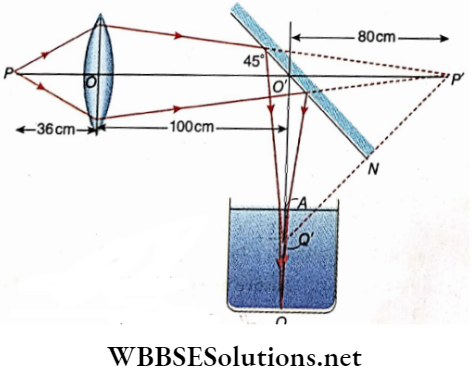
According to the equation of lens
⇒ \(\frac{1}{v}-\frac{1}{u}=\frac{1}{f}\)
⇒ \(\frac{1}{v}+\frac{1}{36}=\frac{1}{30}\)
Or, \(\frac{1}{v}=\frac{-1}{36}+\frac{1}{30}=\frac{1}{180}\)
v = 180 cm
So, If the piano mirror was absent, the Imoge would be formed at a P’ nt n distance of 180 cm behind the lens .
But due to the reflection In the plane mirror, the Image should be formed at Q below the principal axis at a distance, BO cm P’N=Q’N (P’N IS normal to mirror),’ Therefore in bP’O’Q’, O’Q’ = O’P’ = 80 cm]. However, due to refraction in the water of the vessel, the final image Is formed at Q, situated at the bottom of the vessel.
According to the formula
⇒ \(\frac{A Q}{A Q}\)
Or, \(\frac{4}{3}=\frac{20}{A Q^{\prime}}\)
Or, AQ’ = 15 cm
QQ’ = AQ-AQ’ = 20-15 = 5 cm
Distance of the bottom of the vessel from the axis of the lens
= 80 + 5 = 85 cm
Conceptual Questions on Image Formation by Spherical Lenses
Example 28. A convex lens of focal length 20 cm Is placed on a plane mirror. An object, If placed centrally along the axis of the lens at a distance of 20 cm above the lens, where will the image be formed?
Solution:
Here, u = -20 cm , f = 20 cm , v = ?
According to the equation of lens
⇒ \(\frac{1}{v}-\frac{1}{u}=\frac{1}{f}\)
⇒ \(\frac{1}{v}-\frac{1}{-20}=\frac{1}{20}\)
Or, \(\frac{1}{v}\) = 0, v = ∞
Therefore, the refracted rays proceeding parallel to the axis of the lens will be incident perpendicularly on the plane mirror. Hence, the reflected rays will retrace the same path and will form an image which will coincide with the object at O
Example 29. A point object is placed at a distance of 15 cm from a convex lens and its image is formed at a distance of 30 cm on the opposite side of the lens. If a concave lens, the image shifts 30 cm more away from the combination of lenses find the focal lengths of the lenses
Solution:
For the image formation by the convex by lens only u = -15cm, v= 30 cm, f=?
According to the lens equation
⇒ \(\frac{1}{v}-\frac{1}{u}=+\frac{1}{f}\)
⇒ \(\frac{1}{30}-\frac{1}{-15}=\frac{1}{f}\)
Or, \(\frac{1+2}{30}=\frac{1}{f}\)
Or, f = 10 cm
The focal length of the convex lens = 10 cm
An image formed by the convex lens will act as the virtual object for the concave lens and its real image will be formed at a distance of 60 cm from the concave lens
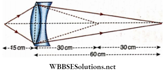
For the image formation by the concave lens
u = +30 cm, v = +60 cm, f- ?
From the equation, \(\frac{1}{v}-\frac{1}{u}=\frac{1}{f}\) we get
⇒ \(\frac{1}{60}-\frac{1}{30}=\frac{1}{f}\)
Or, \(\frac{1-2}{60}=\frac{1}{f}\)
Or, f = -60 cm
The focal length of the concave lens =-60 cm
Example 30. r A converging beam of rays converges to the point P. A lens is placed at a distance of 12 cm from point P in the path of the rays. Where will the converging beam of rays meet if
- The lens is a convex one of focal length 20 cm or
- The lens is a concave one with a focal length of 6 cm
Solution:
The converging beam of rays after refraction in the convex lens LL’ meets at the point Q. In the absence of the lens, the beam of rays would meet at P [Fig. 3.67]. In this case, P is the virtual object and Q is its real image with respect to the lens.
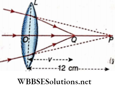
Here, u = 12 cm; f= 20 cm; v = ?
From to the equation of lens
⇒ \(\frac{1}{v}-\frac{1}{u}=\frac{9}{f}\)
Or, \(\frac{1}{v}-\frac{1}{12}=\frac{1}{20}\)
Or, \(\frac{1}{v}=\frac{1}{20}+\frac{1}{12}=\frac{2}{15}\)
Or, \(\frac{15}{2}\)cm = 7.5
So, the beam of rays will meet at Q at a distance of 73 cm from the lens.
The converging beam of rays after refraction in the concave lens LLf appears to diverge from point Q. So in this case the object is virtual and its image is also virtual
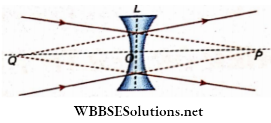
Here, u = 12 cm,f = -6 cm, v = ?
According to the equation of lens,
⇒\(\frac{1}{v}-\frac{1}{u}=\frac{1}{f} \quad \text { or, } \quad \frac{1}{v}-\frac{1}{12}=\frac{1}{-6}\)
Or, \(\frac{1}{v}=\frac{1}{12}-\frac{1}{6}=\frac{1-2}{12}\)
= \(\frac{-1}{12}\)
Or, v = -12 cm
The negative sign of v indicates that after refraction the beam of rays appears to diverge from Q
Example 31. A convex lens of glass has power- 10.0 D. When this lens is completely immersed in a liquid, it behaves as a concave lens of focal length 50 cm. Determine the refractive index of the liquid. Given that – 1.5
Solution:
Power, P= \(\frac{100}{f(\mathrm{~cm})}\)
Or, f = \(\frac{100}{10}\)
= 10 cm
Now, \(\frac{1}{f}=\left({ }_a \mu_g-1\right) \times\left(\frac{1}{r_1}-\frac{1}{r_2}\right)\)
Or, \(\frac{1}{r_1}-\frac{1}{r_2}=\frac{1}{5}\)
When the lens is immersed in the liquid the focal length of the lens (J) becomes -50 cm
⇒ \(\frac{1}{-50}=\left({ }_l \mu_g-1\right)\left(\frac{1}{r_1}-\frac{1}{r_2}\right)\)
Or, \(\frac{1}{-50}=\left(\frac{a^\mu}{a^\mu}-1\right) \times \frac{1}{5}\)
= Re&active index of the liquid relative to air
Or, \(\frac{a^{\mu_g}}{a_l}-1=-\frac{1}{10}\)
Or, \(\frac{a^\mu}{a^{\mu_l}}-1=-\frac{1}{10}\)
Or, \(\frac{a^\mu g}{a_l \mu_l}=1-\frac{1}{10}=\frac{9}{10}\)
Or, \(\frac{1.5}{a^\mu}=\frac{9}{10}\)
⇒ \(_a \mu_l=\frac{15}{9}\)
= 1.67
The refractive index of the liquid is 1.67
WBCHSE physics class 12 refraction lens notes
Refraction Of Light At Spherical Surface Lens Long Questions And Answers
Question 1. A swimmer underwater sees the objects indistinct inside the water with his uncovered eyes. But if he wears a mask, why does he see them distinctly?
Answer:
The refractive index of water is greater relative to air and the refractive index of water is slightly smaller than that of the ingredient of the human eye. So, the focal length of the uncovered eye increases inside water. Due to the increase in focal length, the power of the eye lens decreases. For this, the images of the objects inside water are formed much behind the retina instead of on it. So the objects appear to be indistinct.
On the other hand, if the swimmer wears a mask, his eyes are in contact with air. So, the rays of light enter the eyes from the air and the focal length of the eye lens does not change. The power of eye-lens remains the same. So, due to the presence of a mask, the swimmer sees the objects inside the water distinctly
Question 2. Shows that a concave lens always produces a diminished and virtual image.
Answer:
According to the equation of lens \(\frac{1}{v}-\frac{1}{u}=\frac{1}{f}\)
For a concave lens, both u and f are negative.
∴ \(\frac{1}{v}-\frac{1}{u}=\frac{1}{f}\)
= \(\frac{-(f+u)}{u f} \text { or, } v=\frac{-u f}{u+f}\)
Now, for any value of u, v is negative.
So, the image is formed on the same side as the object and is virtual
From the equation of lens , \(\frac{1}{v}-\frac{1}{u}=\frac{1}{f}\), we get
Or, \(\frac{u}{v}-1=\frac{u}{f}\)
[ m = \(\frac{1}{m}-1=\frac{u}{f}\) [m = \(\frac{v}{u}\) Linear magnification]
Or, \(\frac{1}{m}=1+\frac{u}{f}\)
Or, \(m=\frac{f}{f+u}\)
Now, since both u and f are negative, m < 1
Again, m = \(\frac{\text { length of the image }}{\text { length of the object }}\)
∴ \(\frac{\text { length of the image }}{\text { length of the object }}<1\)
∴ Length of the image < length of the object
Real-Life Scenarios Involving Refraction through Lenses
Question 3. Can a concave lens form a real image?
Answer:
A concave lens can form a real image if the object is virtual or if the lens is placed in a medium whose refractive index is greater than the refractive index of the material of the lens.
Question 4. A concave lens of refractive index μ is immersed in a medium whose refractive index
- Is smaller than μ,
- Is equal to μ,
- Is greater than μ.
When a parallel beam of rays is incident on the lens, show with the help of a diagram in each case the path of the rays.
Answer:
Suppose, the refractive index of the medium = μ’
1. If μ’ < μ, i.e., if the refractive index of the material of the lens is greater than that of the medium, the concave lens behaves as a diverging lens. So, in this case, a beam of rays paraÿel to the axis of the lens, after in the lens, appears to diverge from a point on the principal axis
2. If μ’ = μ, i-e., if the refractive index of the material of the lens and that of the medium are equal, ho refraction oflight
Takes place inside the lens. So, in this case a beam of rays, parallel to the axis of the lens, after refraction in the lens, emerges as a parallel beam. So, on observation of the behaviour of the light rays, it can be said that there is no existence of the lens.
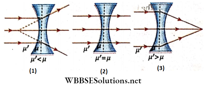
3. If μ’ > μ, i.e., if the refractive index of the material of the lens is less than that of the medium, the concave lens behaves as a convex lens i.e., a converging lens. So, in this case a beam of rays parallel to the axis of the lens, after refraction in the lens, converges to a point on the principal axis of the lens.
Question 5. Show that the minimum distance between an object and its real image formed by a convex lens is four times the focal length of the lens.
Answer:
In the case of the formation of a real image by the convex lens we have,
⇒ \(\frac{1}{v}+\frac{1}{u}=\frac{1}{f}\) ………………….. (1)
If D be the distance between the object and the screen i.e., the image, then
u + v = D
Or, D \((\sqrt{u})^2+(\sqrt{v})^2\)
Or, D \((\sqrt{u}-\sqrt{v})^2+2 \sqrt{u v}\)
Now, D will be the minimum, if \(\sqrt{u}=\sqrt{v}\)= 0
i.e if \(\sqrt{u}=\sqrt{v}\)
Or, u = v
So from equation (1), we get
⇒ \(\frac{1}{u}+\frac{1}{u}=\frac{1}{f}\)
Or,\(\frac{2}{u}=\frac{1}{f}\)
u = 2f
v = 2f
Dmin = 2f+2f = 4f
Question 6. How does the focal length of a lens depend on The colour of the incident light and The Medium surrounding the lens
Answer:
Suppose, the refractive index of the lens relative to the surrounding medium is ft; the radii of curvature of the first and the
The second refracting surfaces of the lens are r1, and r2 respectively. 1ff be the focal length of the lens, then
⇒ \(\frac{1}{f}=(\mu-1)\left(\frac{1}{r_1}-\frac{1}{r_2}\right)\) ……………………… (1)
1. We know that if the wavelength of the incident light ~ increases, the refractive index of any medium (suppose, the material of the lens) decreases according to Cauchy’s relation, μ = A +\(\frac{B}{\lambda^2}\) can be said from the equation
⇒ \(f \propto \frac{1}{(\mu-1)}\) ………………….. (2)
So, if the refractive index of the material of the lens ft decreases, the focal length of the lens increases. Similarly, if the wavelength of light decreases, the refractive index of a medium increases and the focal length of the lens decreases.
In comparison to the wavelength oflight of other colours, the wavelength of red light is greater. So, the focal length of a lens is greater for red light in comparison to other colours.
2. In equation (1), it is the refractive index of the lens relative to the surrounding medium. Now, if the refractive index of the surrounding medium increases, ft decreases. So from equation (2), it can be said that the focal length of a lens increases if ft decreases.
Similarly, if the refractive index of the surrounding medium decreases, μ increases. With the increase of μ, the focal length of the lens decreases
Question 7. The lens is made of two different materials. A point object is placed on the axis of the lens. How many images of the object will be formed?
Answer:
The lens is made of two different materials i.e., it is made up of two materials of different refractive indices. So, the portions of the lens coloured in different will behave as two lenses of two different focal lengths. So, two images of the object will be formed
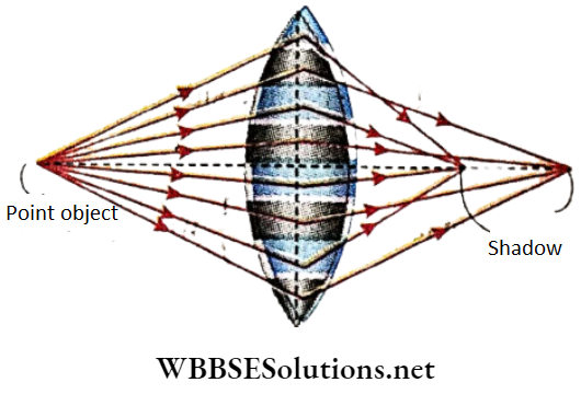
Question 8. Prove that the area of the image of the moon formed by a convex lens is proportional to the square of the focal length of the lens. What change of the image will be observed if a portion of the lens is covered by black paper?
Answer:
Suppose, the angular radius of the moon = θ As the moon is situated from the lens at infinite distance, the image of the moon is formed in the focal plane of the lens. The Image of the centre of the moon is formed at F, the focus of the lens. The rays of light coming from the circumference of the moon are inclined at angle θ with the principal axis of the lens
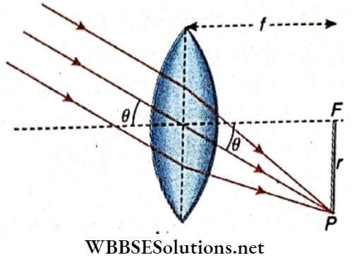
Radius of the image = r = FP = fθ [∴ θ is small]
Area of the image of the moon, A = μr² =μf² θ²
An ∝ f² [ ∴ μ and θ are constants]
If a portion of the lens is covered by black paper, the nature of the image does not change. Only the brightness of the image decreases because comparatively a few light rays take part in the formation of the image.
Question 9. How should the two convex lenses be placed so that a parallel beam of rays emerges out parallel after refraction through the lenses?
Answer:
If the axes of the two lenses are along the same straight line and the distance between the two lenses is equal to the sum of the focal lengths of the lenses, a beam of parallel rays will emerge as a parallel beam after refraction through the lenses
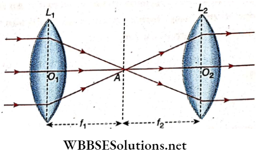
Suppose, the focal lengths of the two lenses L1 and L2 are f1 and f2 respectively. A beam of parallel rays parallel to the principal axis, after refraction on the lens L1, forms the image at A, the focus of the. Lens L1. So, O1A = f1. This image acts as the object for the lens L2. If point A is at a distance of f2 from the second lens, L2 i.e., if AO2 = f2, the rays emitted from A, after refraction in lens L2, emerge as a parallel beam
O1O2 = O1A+AO2= f1+f2
Question 10. A lens is immersed in a liquid so that it vanishes. State the optical nature of the liquid. Find the value of the focal length of the lens from the lens maker’s formula under the above condition
Answer:
The lens will vanish while immersing in a liquid if it has a refractive index equal to that of the material of the lens, i.e., no deviation or lateral displacement of light is observed. 1ff be the focal length of a lens, we get from the lens maker’s for¬ mula
⇒ \(\frac{1}{f}\) = (1μ2-1) \(\left(\frac{1}{r_1}-\frac{1}{r_2}\right)\)
1μ2= Refractive index of the material of the lens relative to the surrounding medium
If the refractive index of the material of the lens and that of the surrounding medium are equal, then 1μ2 = 1.
So, from the above equation, we get
⇒ \(\frac{1}{f}\) = 0
Or, f = ∞
Question 11. An object is moving with velocity Vo along the axis of a convex lens. If m be the magnification at any moment, then what will be the. velocity of the image?
Answer:
The equation of lens is \(\frac{1}{v}-\frac{1}{u}=\frac{1}{f}\)
Differentiating this equation concerning t we get
⇒ \(-\frac{1}{v^2} \frac{d v}{d t}+\frac{1}{u^2} \frac{d t}{d t}\)
Or, \(\frac{v^2}{u^2}\) × Vo
∴ Velocity of the image = \(\frac{v^2}{u^2} \times \text { velocity of the object }\)
V1= Velocity of the image
Vo = Velocity of the object
Or, \(v_1=m^2 \times v_0\)
∴ m= \(\frac{v}{u}\) = Linear magnification
Velocity of the image = \(\)
Or, \(\)
The velocity of the image, V= a velocity of the object
m = linear magnification
Question 12. Explain briefly with a diagram how it is possible to determine the focal length of a concave lens by using a convex lens.
Answer:
In general, a concave lens cannot form a real image. So by casting on a screen the location of the image cannot be measured. A convex lens L1 is taken in contact with a concave lens L2 If the focal length of the convex lens is smaller than that of the concave lens, the combination will act as a convex lens.
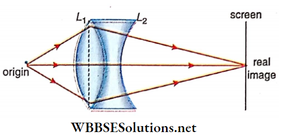
Under this condition, the real image of an object can be formed on a screen. By measuring object distance u and image distance v and using the relation \(\frac{1}{v}-\frac{1}{u}=\frac{1}{F}\) the equivalent focal length, F of the lens-combination can be calculated.
Now, if the focal length of the convex lens and the concave lens are f1 and f2 respectively, then
⇒ \(\frac{1}{F}=\frac{1}{f_1}+\frac{1}{f_2} \text { or, } \frac{1}{f_2}=\frac{1}{F}-\frac{1}{f_1}\)
Or, \(f_2=\frac{F f_1}{f_1-F}\)
So, if the focal length of the convex lens f1 is known, the focal length of the concave lens f2 can be calculated. Here, f1 and F are both positive. So, for the calculation of f2 these positive values are to be put in the above equation and f2 will be negative
Question 13. Show that for any convex lens, the general equation of \(\frac{1}{v}+\frac{1}{u}=\frac{1}{f}\) represents a rectangular hyperbola.
Answer:
For a convex lens, the general equation of a lens can be written as
⇒ \(\frac{1}{v}-\frac{1}{u}=\frac{1}{f}\)
uv- f(u+v) = 0 Or, uv- f(u+v)+f² = f²
⇒ \(f^2-f(u+v)+\left(\frac{u+v}{2}\right)^2-\left(\frac{u-v}{2}\right)^2\) = f²
⇒ \(\left(f-\frac{u+v}{2}\right)^2-\left(\frac{u-v}{2}\right)^2=f^2\)
Or, x² – y² = f²
Where x= \(f-\frac{u+v}{2}\) and y= \(y=\frac{u-v}{2}\)
The above equation represents a rectangular hyperbole
Question 14. The radius of curvature of a plano-convex lens made of a material of refractive index 1.5 is 30 cm. Its concave surface is silvered. At what distance from the plane surface .of the lens is an object to be placed so that a real image equal to the size of the object is formed?
Answer:
This is an optical system with two elements: a convex lens and a concave mirror in contact with each other. For focal length / of the convex lens
∴ \(\frac{1}{f}=(\mu-1)\left(\frac{1}{r_1}-\frac{1}{r_2}\right)\)
⇒ \((1.5-1)\left(\frac{1}{\infty}-\frac{1}{-30}\right)\)
= 0.5 \(\frac{1}{30}\)
∴ f = \(\frac{3.0}{0.5}\)
= 60 cm
Focal length of the concave minor,
F = \(\frac{r_2}{2}=-\frac{30}{2}\)
= -15 cm
Let, u = object distance from the optical system [Fig. 3.75].
Then, for the convex lens
⇒ \(\frac{1}{v}+\frac{1}{u}=\frac{1}{f}, \text { or, } \frac{1}{v}=\frac{1}{f}+\frac{1}{u}\)
⇒ \(\frac{u+f}{u f}, \text { or } v=\frac{u f}{u+f}\)
∴ Magnification in the lens m = \(\frac{v}{u}=\frac{f}{u+f}\)
Now, v = U = object distance for the concave mirror. So
⇒ \(\frac{1}{V}+\frac{1}{U}=\frac{1}{F}\)
Or, \(\frac{1}{V}=\frac{1}{F}-\frac{1}{U}=\frac{U-F}{U F}\)
Or, V = \(\frac{U F}{U-F}\)
Magnification in the mirror M = \(\frac{V}{U}=\frac{F}{U-F}\)
Then, overall magnification,
Mo = mM = \(\frac{f}{u+f} \cdot \frac{F}{U-F}\)
= \(\frac{f}{u+f} \cdot \frac{F}{\frac{u f}{u+f}-F}\)
= \(\frac{f}{u+f} \cdot \frac{F(u+f)}{u f-u F-f F}\)
= \(\frac{f F}{u(f-F)-f F}\)
Given, object and image sizes are equal, i.e., MQ =i
fF = u(f- F) -fP or, u(f-F) = 2fF
Or, \(\frac{2 f F}{f-F}\)
Putting these values off and F, to have
u = \(\frac{2 \times 60 \times(-15)}{60-(-15)}\)
= \(-\frac{2 \times 60 \times 15}{75}\)
= -24 cm
Question 15. The focal length of the equi-convex lens is if the lens is cut into two pieces h along AB, what will be the focal length of each half
Answer:
Let the radius of curvature of each surface of the biconvex lens be r and the refractive index of its material be, From the lens maker’s formula We have
⇒ \(\frac{1}{f}=(\mu-1)\left(\frac{1}{r_1}+\frac{1}{r_2}\right)\)
= \((\mu-1)\left(\frac{1}{r}+\frac{1}{r}\right)=\frac{2}{r}(\mu-1)\) ……………. (1)
For each half, the radius of curvature of the curved surface r1 = r and that for the plain surface, r2 = ∞
Let us suppose that the focal length of each of the cut pieces be x.
⇒ \(\frac{1}{x}=(\mu-1) \frac{1}{r}=\frac{1}{2 f}\)
From Equation
x = 2f
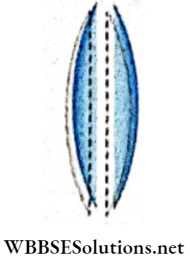
Question 16. If the light rays behave, what will be the relation among μ1, μ and μ2?
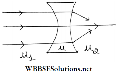
Answer:
Since the light fays after entering the lens proceed undefeated, the refractive index of the left-hand medium of the lens and that of the material of the lens are the same, i.e., μ1 = μ.
Again, as the rays after emerging out from the second surface of the concave lens become convergent instead of divergent rays, it may be concluded that the refractive index of the right-hand medium is greater than that of the material of the lens i.e., μ1 > μ.
Question 17. An object behaves like a convex lens in air but like a concave lens in water. What is the type of refractive index of its material concerning air and water
Answer:
For a convex lens,
⇒ \(\frac{1}{f}=\left(\frac{\mu_2}{\mu_1}-1\right)\left(\frac{1}{r_1}+\frac{1}{r_2}\right)\) ……………… (1)
Here, μ2 is the refractive index of the material and μ1 is that of the surrounding medium. f is positive for a convex lens. From, equation (1), it can be said that f will be positive if μ2 >μ1 i.e., if the refractive index of the material of the object is greater than that of air.
For a concave lens. f is negative. From equation (1), it can be said that f will be negative if μ2 < μ1 i.e. if the refractive index of the material of the object is less than that of water. So, the refractive index of the material of the object is greater than air but less than water.
Question 18. A convex lens and a concave lens of equal focal length are placed in contact. What are the focal length and power of the lens combination?
Answer:
If focal length of convex lens, f1 = f, then focal length of concave lens, f2 = -f
If F be the focal length of the lens combination, then
⇒ \(\frac{1}{F}=\frac{1}{f_1}+\frac{1}{f_2}=\frac{1}{f}+\frac{1}{-f}\)
Or, F = ∞
Power of the lens combination = \(\frac{1}{F}\) = 0
Question 19. If the plane surface of a plano-convex lens is silvered, what will be the effective (or equivalent) focal length of the lens
Answer:
If an object is placed in front of such a lens, light rays are at first refracted through the convex surface. Next, by reflect¬ ing from the silvered plane surface, the light rays are refracted through the convex surface for the second time.if the equivalent focal length of the lens is F, then
⇒ \(\frac{1}{F}=\frac{1}{f}+\frac{1}{f_m}+\frac{1}{f}\)
[Where f is the focal length of the convex surface and fm focal length of the silvered plane surface]
Or, \(\frac{1}{F}=\frac{2}{f}+\frac{1}{f_m}\)
Or, \(\frac{1}{F}=\frac{2}{f}\)
Since the focal length of the silvered plane
Surface fm = ∞, So \(\frac{1}{f_m}\) = 0
∴ F = \(\frac{f}{2}\)
Question 20. The focal length f of an equi-convex lens is related to the radius of curvature r of the surface by f = r, find out the refractive index of the material of the lens.
Answer:
From the lens maker’s formula,
⇒ \(\frac{1}{f}=(\mu-1)\left(\frac{1}{r_1}-\frac{1}{r_2}\right)\)
For a equi-convex lens, r1 = r ; r2 = -r
∴ \(\frac{1}{f}=(\mu-1) \cdot \frac{2}{r}\)
Or, \(\frac{1}{r}=(\mu-1) \frac{2}{r}\)
Since by the question f = +r
Or, \(\mu-1=\frac{1}{2}\)
Or, μ = \(\frac{3}{2}\)
= 1.5
Question 21. Sunglasses (Goggles) have two curved surfaces yet their power is zero, Why?
Answer:
The two radii of curvature of the two surfaces of the lens used in sunglasses are equal and of the same sign (curved in the same direction) and also thickness of the glass is very small
Power = \(\frac{1}{f}=\left(a_g \mu_g-1\right)\left(\frac{1}{r_1}-\frac{1}{r_2}\right)\) = 0
∴ r1 = r2
Question 22. What is the relation between the refractive indices μ, μ1 and μ2 if the behaviour of light rays.
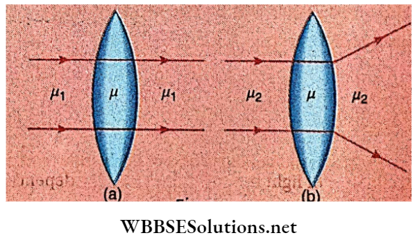
Answer:
Let a lens of material of refractive index μ is placed in a medium of refractive index
The focal length is given by,
⇒ \(\frac{\mu}{\mu_1}-1\) = 0
⇒ \(\left(\frac{1}{r_1}-\frac{1}{r_2}\right)\) = 0
According to the = oo [because the lens behaves as a plane a glass plate
∴ \(\frac{\mu}{\mu_1}-1\)
Since \(\left(\frac{1}{r_1}-\frac{1}{r_2}\right)\) ≠ 0
Or, μ = μ1
According to the the lens acts as a concave lens. Sof is negative.
The focal length of the lens is given by,
∴ \(\frac{1}{f}=\left(\frac{\mu}{\mu_2}-1\right)\left(\frac{1}{r_1}-\frac{1}{r_2}\right)\) = 0
Since in case of a convex lens \(\) >0
Therefore \(\left(\frac{\mu}{\mu_2}-1\right)\) < 0
Or μ < μ2
Question 23. The f-number of a lens is given by \(\frac{F}{D}\) where F is its focal length and D is aperture diameter. If the f-number is 1.6 instead of 2, determine the amount of excess light that will fail on the film.
Answer:
We know, f-number \(=\frac{F}{D}\)
Or, D = \(=\frac{F}{f \text {-number }}\)
Suppose, when f-number = f1; D = D1 and when f-number
So from equation (1) we get
⇒ \(\frac{D_2}{D_1}=\frac{f_1}{f_2}\)
Now the amount of light that will reach the film depends on the area of the aperture Le., on D²
So, \(\frac{\text { the amount of tight in the second case }}{\text { the amount of light in the first case }}=\frac{D_2^2}{D_2^2}\)
⇒ \(\frac{2^2}{16^2}=\frac{1}{64}\)
Therefore, if the f-number of the lens, changes from 2 to 1. 6 the amount of light falling on the film will be \(\frac{1}{64}\) of the first case
Question 24. The aperture of the camera lens is changed from \(\frac{f}{8}\) to \(\frac{f}{11}\) to, How are
- The size of the image
- The intensity of illumination of the
- Exposure time and
- The distinctness of the image influenced
Answer:
When the f-number of the lens is changed from f-8 to tof-11 the effective aperture of the lens decreases.
So,
- The size of the image will not be changed,
- The intensity of illumination of the image will be diminished as less amount of light passes through the lens.
- Exposure time will be lengthened.
- Distinctness of the image will increase
Question 25. The radius of curvature of both sides of the given lens is R. The Refractive index of the fV medium in which the source is present is μ1, and the refractive indices of the lens and the medium in which the image is formed are μ2 and μ3 respectively. Find the focal length of the system.
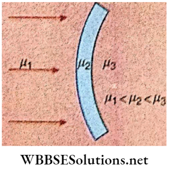
Answer: In case of refraction at the first curved surface,
⇒ \(\frac{\mu_2}{v_1}+\frac{\mu_1}{\infty}=\frac{\mu_2-\mu_1}{+R}\) ………………………. (1)
Again, for refraction at the second curved surface object distance is equal to the distance of the image formed by the first refracting surface since the lens is a thin lens
⇒ \(\frac{\mu_3}{v_2}-\frac{\mu_2}{v_1}=\frac{\mu_3-\mu_2}{+R}\) …………. (2)
Adding equations (1) and (2), we get
⇒ \(\frac{\mu_3}{v_2}=\frac{\mu_3-\mu_1}{R}\)
Hence the focal length of the system,f \(\frac{\mu_3 R}{\mu_3-\mu_1}\)
Question 26. An equl convex lens with radii of curvature each of magnitude r is kept over a liquid layer poured on top of a plane mirror. A small needle with its tip on the principal axis of the lens is moved along the axis until its inverted real image coincides with the needle itself. The distance of the needle from the lens is measured to be x On removing the liquid layer and repeating the experiment, the design 3.82 stance is found to be y. Prove that the refractive index of the liquid.
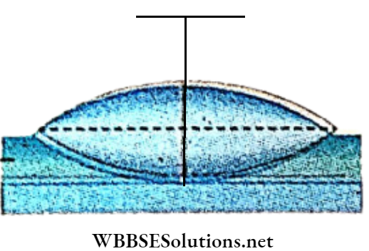
Answer:
From the given conditions, we get the equivalent focal length of the combination of glass lens and liquid lens, F = x and the focal length of convex lens, f1 = y.
If f2 is the focal length of the liquid lens then
⇒ \(\frac{1}{f_1}+\frac{1}{f_2}=\frac{1}{F} \text { or, } \frac{1}{f_2}=\left(\frac{1}{x}-\frac{1}{y}\right)\)
The liquid lens is a plano-concave lens for which
R1 = -r and R2 =∞
From the lens maker’s formula,
⇒ \(\frac{1}{f_2}=(\mu-1)\left(\frac{1}{R_1}-\frac{1}{R_2}\right)\)
⇒ \(\left(\frac{1}{x}-\frac{1}{y}\right)=(\mu-1)\left(\frac{1}{-r}-\frac{1}{\infty}\right)\)
Or, \((\mu-1)=r\left(\frac{1}{y}-\frac{\mathrm{i}}{x}\right)\)
⇒ \(1+\frac{r}{y}-\frac{r}{x}\)
Question 27.
- Determine the effective focal length of the combination of two lenses, one a convex lens of focal length 30 cm and the other a concave lens of focal length 20 cm placed 8.0 cm apart with their principle axis coincident. Does the answer depend on which side of the combination a beam of parallel light is incident?is the notion of effective focal length of this system useful at all?
- An object 1. 5 cm in size is placed on the side of the convex lens. The distance between the object and the
Answer:
Convex lens s 40an. Detersirs* the oagrtifkation produced by the two-knows system. and she sze os she image.
1. When a beam of a parallel beam of light is incident on the convex lens then.
u1 =∞
f1 = 30 cm
This image is the virtual o&jecrssrthesecondfens
u2= 30-8 = 22 cm, f2= – 20 cm
∴ \(\frac{1}{v_2}=\frac{1}{f_2}+\frac{1}{u_2} \text { or, } u_2=\frac{-20 \times 22}{+22-20}\)
= -220 cm
The focal length of the combination is (220-4) = 216 cm from the midpoint of the line joining the lenses when the light falls on the convex lens first
When the beam of light is incident on the concave lens first then f1 = -20 cm, u = ∞
∴ v1 = -20 cm
This image Is the virtual object for the convex lens
∴ f2 = 30 cm, u2 = (20 + 8) cm
= -28 cm
∴ \(v_2=\frac{u_2 f_2}{u_2+f_2}=\frac{-28 \times 30}{30-28}v_2=\frac{u_2 f_2}{u_2+f_2}=\frac{-28 \times 30}{30-28}+\)
So in this case the focus of the combination is at a distance (420-4) = 416 cm to the right from the mid¬ point of the line joining the two lenses.
Thus the answer depends on the lens nn which the length is first incident as there is no definite formula based on which the focal length of the combination can he calculated, the notion of effective focal length is not useful at all
2. For the first lens, u1= -40 cm, f1 = 30 cm
∴ \(\frac{1}{v_1}=\frac{1}{f_1}+\frac{1}{u_1} \quad \text { or } \quad v_1=\frac{u_1 f_1}{u_1+f_1}\)
∴ v1= \(\frac{-40 \times 30}{-40+30}\)
= 120 cm
∴ Magnification by the convex lens,
m1 = \(\frac{v_1}{u_1}=\frac{120}{40}\)
= 3
Forthesecondlens, u2 = +120 – 8
= 112 cm
∴ Virtual object, f2 = -20 cm
∴ \(\frac{1}{v_2}=\frac{1}{u_2}+\frac{1}{f_2}\quad \text { or, } v_2=\frac{1}{u_2+f_2}\)
v2 = \(\frac{+112 \times 20}{+112-20}=-\frac{112 \times 20}{92}\) cm
Magnification \(m_2=\frac{v_2}{n_2}=\frac{112 \times 20}{92 \times 112}=\frac{20}{92}\)
∴ Total magnification,
m = m1× m2= 3 × \(\frac{20}{92}\)
= 0.652
∴ Size of the image = 1.5 × 0.652
= 0.98 cm
Question 28. Acaid-sheet divided into squares each of size 1 mm² is being viewed at a distance of 9 cm through a magnifying glass (a {YipvpT’PTnglens of focal length 10 cm ) held close to the eye.
What is the magnification produced by the lens? How much is the area of each square in the virtual image ?
- What is the angular magnification (magnifying power) of the lens? ‘
- Is the magnification in (a) equal to the magnifying powerin (b)? Explain. *
- At what distance should the lens be held from the cardboard in order to view the squares distinctly with the maximum possible magnifying power
- What is thelinear magnification in this case?
- Is the linear magnification equal to the magnifying power in this case? Explain.
- What should be the distance between the object and the magnifying glass if the virtual image of each square is to have an area 6.25 mm2?
- Would you be able to see the squares distinctly with your eyes very close to the magnifier?
Answer:
1. In the case of a convex lens,
⇒ \(\frac{1}{v}=\frac{1}{f}+\frac{1}{u}\)
Here , f= 10 cm , u= -9 cm
= \(\frac{1}{10}-\frac{1}{9}\)
Or, v = 90 cm
∴ Linear magnification
m = \(\frac{v}{u}=\frac{-90}{-9}\)
= 10
Length of each side of the square
= 1 × 10 mm = 1 cm
∴ Area of each square in the virtual image = 1 cm²
2. Angular magnification
= \(\frac{\text { distance of near point }}{\text { object distance }}=\frac{25}{9}\)
= 2.8
3. The magnification in (a) = 10 and magnifying power in (b) =2.8 , So the two are not equal. But when the object is placed at the nearpoint, then only the two would become equal.
4. When the image is formed at the near point, the magnification is maximum:
1n that case, v = -25 cm and f = 10 cm
⇒ \(\frac{1}{u}=\frac{1}{v}-\frac{1}{f}=-\frac{1}{25}-\frac{1}{10}\)
Or, u = \(-\frac{25 \times 10}{10+25}\)
= – 7.14 cm
5. Linear magnification:
m = \(\frac{v}{u}=\frac{25}{7.14}\)
= 3.5
6. Angular magnification:
= \(\frac{D}{u}=\frac{25}{7.14}\)
= 3.5 = Linear magnification
The image distance and least distance of distinct vision Are equal in this case. Thus the linear magnification and angular magnification are equal
7. Area of enlarged square = 6.25 mm²
Length of each side of the enlarged square
= \(\sqrt{6.25}\)
= 2.5mm
Magnification \(\frac{v}{u}=\frac{2.5}{1.0}\)
= 2.5
v = 2.5 u
From lens equation
⇒ \(\frac{1}{u}=\frac{1}{v}-\frac{1}{f}\)
Or \(\frac{1}{u}=\frac{1}{2.5 u}-\frac{1}{10}\)
u = – 6cm
The object should be placed at a distance of 6 cm from the lens.
8. When the eye is kept very near the lens the image formed will be within the least distance of distinct vision and it can not be observed distinctly.
Question 29. An equi-convex lens (of refractive indexi.50 ) in contact with a liquid layer on top of a plane mirror A small needle with its tip on the principal axis moves along the axis until an inverted image is found at the position of the needle. The distance of the needle from the lens is measured to be 45.0 cm. The liquid is removed and the experiment is repeated. The new distance is measured to be 30.0 cm. What is the refractive index of the liquid?
Answer:
The rays oflight from the pin are first refracted from the lens liquid combination and then reflected by the mirror at the bottom of the combination. Since the image coincides with the object, the beam incident on the mirror is a parallel beam oflight. Thus it is obvious that the pin is situated at the focal length of the lens-liquid combination, i.e.,f = 45 cm
In the absence of the liquid, the position of the pin is the focal point of the equi-convex lens i.e., f1 = 30 cm. Let the focal length of the liquid plano-concave lens be f2
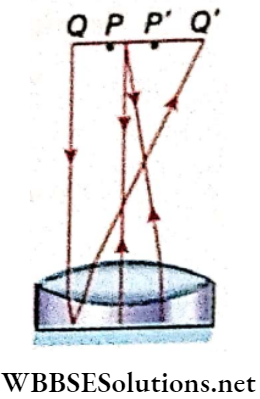
Then \(\frac{1}{f_1}+\frac{1}{f_2}=\frac{1}{f}\)
∴ f2 = -90 cm
From lens maker’s formula
⇒ \(\frac{1}{f}=(\mu-1)\left(\frac{1}{R_1}-\frac{1}{R_2}\right)\)
For the equi-convex lens,
f1 = 30, μ = 1.5, R1 = R and R2 = -R
⇒ \(\frac{1}{30}=(1.5-1) \times \frac{2}{R}\)
R = 30 cm
For the liquid plano-concave lens
f2 = -90 cm, μ = μ’ (say), R1 = -30 cm, R2 = ∞
⇒ \(-\frac{1}{90}=\left(\mu^{\prime}-1\right)\left(-\frac{1}{30}-\frac{1}{\infty}\right)\)
μ’ = 1.33

Question 30. A beam of light converges at a point P. Now a lens is placed in the path of the convergent beami2cm from P. At what point does the beam converge if the lens is
- A convex lens of focal length 20cm or
- A concave lens of focal length 16cm?
Answer:
u = 12cm,f = 20cm , v = ?
⇒ \(\frac{1}{v}-\frac{1}{u}=\frac{1}{f}\)
Or, \(\frac{1}{v}=\frac{1}{12}+\frac{1}{20}\)
Or, \(=\frac{12 \times (20)}{12+20}\)
= 7.5 cm
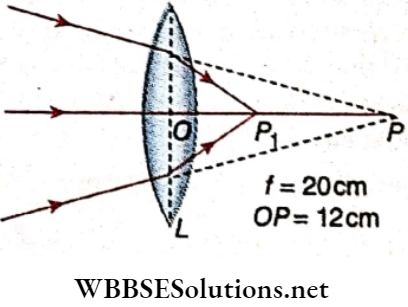
Beam of rays will meet at point P1 at a distance of 7.5cm from the lens
u = 1. 2cm, f= -16cm, v = ?
⇒ \(\frac{1}{v}-\frac{1}{u}=\frac{1}{f}\)
Or, \(\frac{1}{v}=\frac{1}{12}-\frac{1}{16}\)
Or, v = \(\frac{16 \times(12)}{16-12}\)
= 48 cm
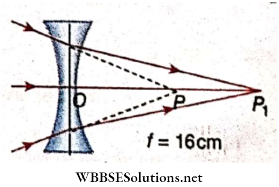
∴ The beam of rays will meet at point Pr at a distance 48cm from the lens.
Question 31. Two lenses, one convex and the other concave are kept in contact. The focal length of a convex lens is 30cm and that of a concave lens is 20cm. What will be the equivalent focal length of the combination? What will be the nature of the combination?
Answer:
For the convex lens, f1 = +30 cm;
For the concave lens, f2 = -20 cm
If the equivalent focal length is F then
⇒ \(\frac{1}{F}=\frac{1}{f_1}+\frac{1}{f_2}\)
Or, \(\frac{f_1 f_2}{f_1+f_2}=\frac{30 \times(-20)}{30+(-20)}\)
⇒ \(\frac{-600}{10}\)
= – 60 cm
Since the equivalent focal length is negative, the combination will act as a concave lens
Refraction Of Light At Spherical Surface Lens Assertion Reason type
Direction: These questions have statement 1 and statement 2. Of the four choices given below, choose the one that best describes the two statements.
- Statement 1 is true, statement 2 is true; statement 2 is a correct explanation for statement 1.
- Statement 1 is true, and statement 2 is true; statement 2 is not a correct explanation for statement 1.
- Statement 1 is true, statement 2 is false.
- Statement 1 is false, and statement 2 is true.
Question 1.
Statement 1: The lens formula \(\) indicates that the focal length of a lens depends on the distances of the object and image from the lens.
Statement 2: The formula does indicate that when u is changed v also changes, so that f of a particular lens remains constant
Answer: 4. Statement 1 is false, and statement 2 is true.
Question 2.
Statement 1: A lens has two principal focal lengths which may differ.
Statement 2: Light can fall on either surface of the lens. The two principal focal lengths differ when the medium on the two sides has different refractive indices
Answer: 1. Statement 1 is true, statement 2 is true; statement 2 is a correct explanation for statement 1.
Question 3.
Statement 1: A convex Jens of glass (mu = 1,5) behave as a diverging lens when 1mmersed 1n carbon disulphide of higher refractive index mu = 1.65
Statement 2: A diverging lens in air is thinner in the middle and thicker at the edges
Answer: 3. Statement 1 is true, statement 2 is false.
Question 4.
Statement-1: The power of a lens depends on the nature of the material of the lens, the medium in which it is placed, and the radii of curvature of its surfaces
Statement-2: It follows from the relation p = \(\frac{1}{f}\) = \((\mu-1)\left(\frac{1}{r_1}-\frac{1}{r_2}\right)\), where the symbol have standard meaning
Answer: 1. Statement 1 is true, statement 2 is true; statement 2 is a correct explanation for statement 1.
Question 5.
Statement 1: If a portion of a Jens is broken then we can gel a complete 1mage of an object with the broken lens,
Statement 2: With his broken lens the intensity of the 1mage format! will he lesser
Answer: 2. Statement 1 is true, and statement 2 is true; statement 2 is not a correct explanation for statement 1.
Question 6.
Statement 1: If a convex lens of focal length f and a concave lens of power \(\frac{1}{f}\) are put 1n contact, then the focal length of the combination Is zero,
Statement 2 : P = \(p_1+p_2=\frac{1}{f_1}+\frac{1}{f_2}\)
Answer: 4. Statement 1 is false, and statement 2 is true.
Refraction Of Light At Spherical Surface Lens Match The Columns
Question 1. Match the position of an object concerning a convex lens in column 1 with the corresponding position of the image in column 2.
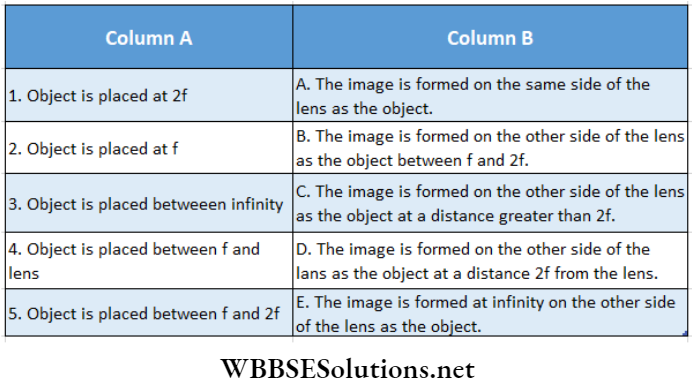
Answer: 1- D, 2-E, 3-B, 4-A, 5-C
Question 2. The nature and size of the image formed by the convex mirror is given in column 1 and the position of the object is given in column 2.
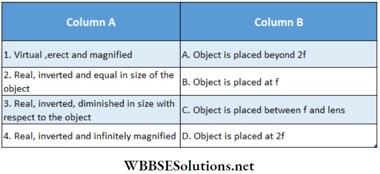
Answer: 1-C, 2-D, 3-A, 4-B
Question 3. Two transparent media of refractive indices μ1 and μ2 have a solid lens-shaped transparent material of refractive index between them as shown in figures in column 2. A ray traversing these media is also shown in the figures. In column 1 different relationships between, μ1, μ2, and μ3 are given. Match them to the ray diagram shown in column 2
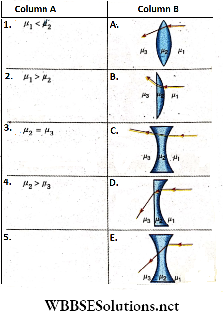
Answer: 1- A, C, 2-B, D, E, 3- A, C, E, 4-B, D
Question 4. Four combinations of two thin lenses are given in column 1. The radius of curvature of all curved surfaces is R and the refractive index of all the lenses is 1.5. Match lens combinations in column 1 with their focal length is column 2
Answer: 1- B, 2-D, 3-C, 4-A