
WBCHSE Class 12 Physics Magnetic Properties Notes
Magnetic Properties Of Materials Introduction
Electric dipole end electric dipole moment:
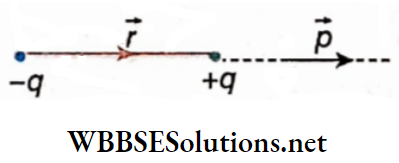
From the chapter ‘Electric Field’ we know that, two equal but opposite charges +q and -q kept close to each other form an electric dipole.
Electric dipole moment \(\vec{p}\) of this di[o;e is defined as:
⇒ \(\vec{p}=q \vec{r}\)….(1)
= magnitude of any charge x position vector of charge +q with respect to charge -q
So, the magnitude of \(\vec{p} \text { is } p=|\vec{p}|=q r\) and the direction is from -q to +q.
Electric field on the axis of an electric dipole: Let p be a point on the axis of an electric dipole. If the distance
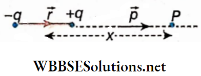
X of the point P from the mid-point of the dipole be much greater than the length r of the dipole, the glottic field at the point P due to that dipole,
⇒ \(\vec{E}=\frac{1}{4 \pi \epsilon_0} \cdot \frac{2 \vec{p}}{x^3}\)
Here, ∈0 = permittivity of air or Vacuum
Read and Learn More Class 12 Physics Notes
= 8.854 x 10⁻¹² C2.N-1.m-2
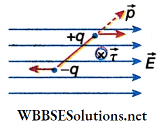
Torque on an electric dipole in a uniform electric field: \(\vec{E}\) is a uniform electric field (-q, +q) is an electric dipole whose dipole moment = \(\vec{p}\).
Now, the torque acting on the dipole due to the electric field \(\vec{E}\) is,
⇒ \(\vec{\tau}=\vec{p} \times \vec{E}\)
In the direction of \(\vec{\tau}\) is particularly downward concerning the page of the tired book, which Is denoted by the symbol\(\otimes\).
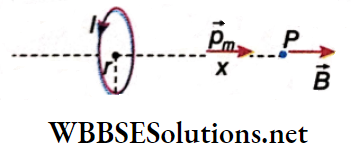
Magnetic field on the axis of a current loop:
r = radius of a circle conductor of a single turn, i.e., the radius of the current loop,
I = current in that loop.
P is any point on the axis of the current loop which is at a distance x from the center of the loop.
WBBSE Class 12 Magnetic Properties Notes
In the chapter ‘Electromagnetism’ we know that the magnetic field produced at the point P due to the current loop is,
⇒ \(B=\frac{\mu_0 I}{2} \cdot \frac{r^2}{\left(r^2+x^2\right)^{3 / 2}}\) [μ0 = magnetic permeability of air or vacuum = 4π x 10-7 Hm-1]
⇒ \(\text { If } r \ll x \text {, then } B \approx \frac{\mu_0 I}{2} \cdot \frac{r^2}{x^3}=\frac{\mu_0 I}{2 \pi} \cdot \frac{\pi r^2}{x^3}=\frac{\mu_0 I}{2 \pi} \cdot \frac{A}{x^3}\)
where, A = πr2 = area of the current loop.
∴ \(B=\frac{\mu_0}{4 \pi} \cdot \frac{2 I A}{x^3}\)
From the corkscrew rule we get, that the direction of \(\vec{B}\) is along the axis of the loop; the direction of \(\vec{B}\) at the point P is outward along the axis. Again, taking that direction as the direction of the area A, it can be expressed as \(\vec{A}\).
Therefore, \(\vec{B}=\frac{\mu_0}{4 \pi} \cdot \frac{2(\overrightarrow{I A})}{x^3}\)….(4)

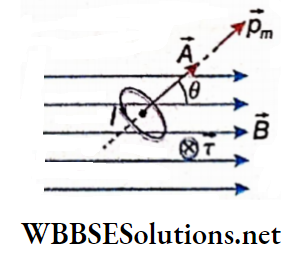
WBCHSE Class 12 Physics Magnetic Properties Notes Torque on a current loop in a uniform magnetic field:
In the chapter ‘Electromagnetism’ we know that, if a current loop of single turn is kept in a uniform magnetic field B, the torque acting on the loop is,
⇒ \(\vec{\tau}=\overrightarrow{I A} \times \vec{B}\)….(5)
The direction of this torque is perpendicularly downward concerning the page of the book, which is denoted by the symbol.
Class 12 Physics Magnetic Properties Of Materials
Magnetic Properties Of Materials Magnetic Dipole And Magnetic Dipole Moment Or Magnetic Moment
Comparing equations (2) and (4) and at the same time equations (3) and (5) as described, we get,
1. Electric field \(\vec{E}\) in electrostatics plays the same role as that of magnetic field \(\vec{B}\) in magnetism.
2. The role of the quantity \(\frac{1}{4 \pi \epsilon_0}\) in electrostatics is the same as that of the quantity \(\frac{\mu_0}{4 \pi}\) in magnetism.
3. The role of electric dipole moment \(\vec{p}\) in electrostatics is the same as the quantity I\(\vec{A}\) related to a current loop in magnetism.
Inference: Any current loop behaves as a magnetic dipole. The dipole moment of this dipole is,
⇒ \(\vec{p}_m=I \vec{A}\)
where, I = current through the loop, \(\vec{A}\) = area vector of the loop.
The magnitude of \(\vec{A}\) is the same as the magnitude of the area of the loop; the direction of \(\vec{A}\) is in the direction of advancement of the screw-head when a right-handed screw is rotated in the direction of current I through the loop.
Naturally, if the current loop contains N turns, it’s the magnetic moment, becoming \(\vec{p}_m=N I \vec{A}\).
Unit of magnetic moment:
Unit of pm = unit of I x unit of A
= ampere.metrer2 (A.m2)
In the CGS or Gaussian system:
The magnetic dipole moment of a current loop, \(\vec{p}_m \equiv I \vec{A}\); if the current loop contains N turns instead of a single turn, \(\vec{p}_m=N I \vec{A}\). Here, the units of
A, I and pm are cm2, emu of current, and emu.m2, respectively.
∴ 1 emu.cm2 = 10A x 10-4 m2
= 10-3 A.m2
Significance: Any current loop behaves as a magnetic dipole-it means that a current loop and a magnet having a north and a south pole are qualitatively equivalent. This similarity is discussed with the help of the following two examples.
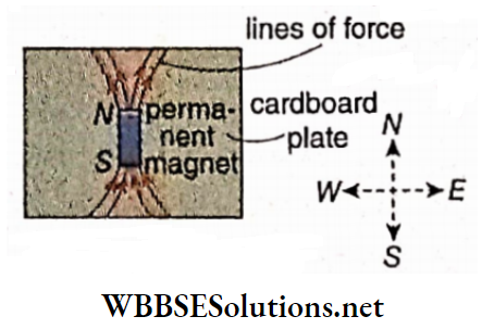
Similarities between a circular conductor and a magnet:
Magnetic lines of force near the center of a circular conductor are almost parallel to each other and they remain perpendicular to the plane of the circle.
So, almost a uniform magnetic field is generated at that region, which acts normally to the plane of the circular conductor.
Short Notes on Ferromagnetism and Paramagnetism
From the properties of magnetic lines of force of a permanent magnet, we know that, if the circular conductor is replaced by a small permanent magnet in that region, similar lines of force will be obtained.
So, we can conclude that a circular current-carrying coil behaves as a permanent magnet.
We can also get the rule for the determination of the polarity of the circular conductor.
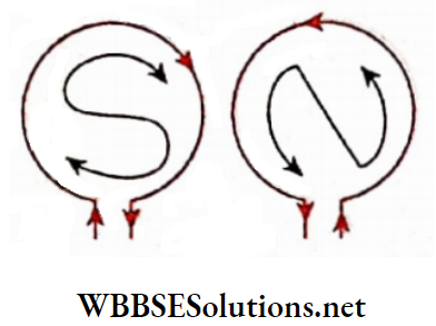
1. The face of a circular conductor on which the current appears to flow clockwise, develops a magnetic south pole.
2. The face of a circular conductor, on which the current appears to flow anticlockwise, develops a magnetic north pole.
With the help of the following experiment, the magnetic property of a circular conductor can be shown.
De la Rives floating battery: In a wide test tube some mercury is taken so that it can float upright in water
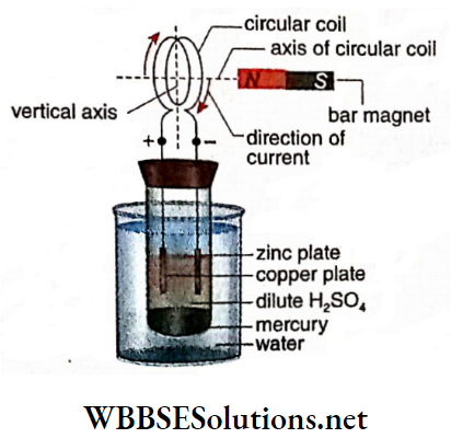
Some dilute sulphuric acid (H2SO4) is poured into the test tube above mercury, and zinc and copper plates are dipped in the acid so that a voltaic cell is formed. This is known as a floating battery.
Two conducting wires from the two plates are brought outside the test tube through a cork fitted at the top.
These two wires act as two poles of the battery. Now the two ends of a circular coil are joined with those two poles. Usually, the coil contains several number of turns instead of a single turn.
When the coil is connected to the battery, the whole system begins to oscillate about a vertical axis.
At last, when the battery comes to rest, the axis of the circular coil sets itself in the north-south direction.
From this directive property, it is understood that the current-carrying coil behaves as a magnet.
With the help of a bar magnet, it can also be observed that like poles repel and unlike poles attract each other.
Class 12 Physics Magnetic Properties Of Materials Similarities between a current-carrying solenoid and a magnet:
The arrangement of the lines of force in the chapter ‘Electromagnetism’ is similar to the arrangement of lines of force of a bar magnet.
On the face, on which the direction of current flow appears clockwise, a magnetic south pole develops, and on the other face of the solenoid, a magnetic north pole develops.
So, we can conclude that a current-carrying solenoid behaves as a permanent bar magnet.
Experimental demonstration:
The magnetic properties of a solenoid can be shown by replacing the circular coil attached to the de la Rive’s floating battery with a solenoid.
In this case, also, the directive and the attractive or repulsive properties of the solenoid with another magnet are also observed.
Actually, from the similarities of a magnet and a current loop, it can be concluded that magnetism is not a separate branch of physics, rather it is a part of electricity and this specific subject is known as electromagnetism.
Pule-sought of a Magnet:
In modem theory of magnetism, the concept of the pole-strength of a magnet is not essential; but for the comparison with electrostatics and also to get an idea about the old theory of magnetism, we may discuss here about the pole-strength of a magnet.
Let a bar magnet NS of effective length r be kept at an angle θ with the direction of a uniform magnetic f field \(\vec{B}\).
The effect on the N and S poles are equal and opposite; hence due to the magnetic field \(\vec{B}\), two equal but opposite forces will act on the two poles.
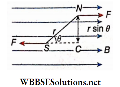
The distance between the line of action of the two forces, NC = rsinθ. So, the torque acting on the bar magnet due to these two forces,
\(\tau\) = magnitude of any one force x perpendicular distance between the two forces
= Frsinθ….(1)
substituting \(\vec{p}_m=I \vec{A}\) we get,
⇒ \(\vec{\tau}=\vec{p}_m \times \vec{B}\)
We get the value of the torque \(\vec{\tau}\),
⇒ \(\tau=p_m B \sin \theta\)
Since a current loop and a magnet are identical, from equations (1) and (2) we get,
⇒ \(F r \sin \theta=p_m B \sin \theta \quad \text { or, } F=\frac{p_m}{r} B=q_m B\)….(3)
The term qm is known as the pole strength of a magnet. The value of the pole-strength of each of the N and S poles is qm; conventionally the pole-strength of the N pole is taken as + qm and that of the S pole is taken as -qm.
Definition:
The ratio of the magnetic moment of a magnet to its effective length is called the pole strength of that magnet.
The strength of the two poles of the magnet is equal but opposite; the strength of the north pole is taken as positive and that of the south pole as negative.
Using the vector symbol, equation (3) can be written as
⇒ \(\vec{p}_m=q_m \vec{r} \text { and } \vec{F}=q_m \vec{B}\)
These two equations are identical to the equations \(\vec{p}=q \vec{r} \text { and } \vec{F}=q \vec{E}\) in electrostatics.
Due to the similarities between the electric field \(\vec{E}\) and magnetic field \(\vec{B}\), we can say that the role of positive arid negative charges (±q) in electrostatics is the same as that of the north and south poles (±qm) in electromagnetism.
Class 12 Physics Magnetic Properties Of Materials Unit of pole-strength:
In SI: \(\text { Unit of } q_m=\frac{\text { unit of } p_m}{\text { unit of } r}=\frac{\mathrm{A} \cdot \mathrm{m}^2}{\mathrm{~m}}=\mathrm{A} \cdot \mathrm{m}\)
In CGS: Unit of qm is emu of current cm;
⇒ \(1 \mathrm{emu} \text { of current } \cdot \mathrm{cm}=10 \mathrm{~A} \times 10^{-2} \mathrm{~m}=\frac{1}{10} \mathrm{~A} \cdot \mathrm{m}\)
The magnetic moment of a magnet: The magnetic moment of a magnet can also be defined from the concept of pole strength.
Definition: The product of the pole-strength of any pole of a magnet and its effective, length is called the magnetic moment of that magnet.
If the distance vector from the south pole to the north pole of a bar magnet is 2\(\vec{l}\) and its pole strength is qm, then the magnetic moment,
⇒ \(\vec{p}_m=2 q_m \vec{l}\)
Mutual force between two magnetic poles: We know that, for a charge q, the electric field at any point at a distance r from the charge = force acting on unit positive charge placed at that point,
⇒ \(\text { i.e., } E=\frac{1}{4 \pi \epsilon_0} \cdot \frac{q}{r^2}\) [∈0 = electrical permittivity of vacuum]
From analogy, we can say that the magnetic field at any point at a distance r from a magnetic pole of pole-strength qm = force acting on a unit north pole placed at that point,
⇒ \(\text { i.e., } B=\frac{\mu_0}{4 \pi} \cdot \frac{q_m}{r^2}\) [μ0 = magnetic permeability of vacuum]
If another magnetic pole of pole-strength ‘m is placed at a distance r from qm, from the equation F = qmB we can say that, force acting on that pole
⇒ \(F=\frac{\mu_0}{4 \pi} \cdot \frac{q_m \cdot q_m^{\prime}}{r^2}\)…(4)
According to Newton’s third law of motion, it is the mutual force acting between the poles having pole strengths qm and I’m. Equation (4) is called Coulomb’s law in magnetism.
If both the poles are north poles or both the poles are south poles, the product qmq’m becomes positive, and hence F is also positive. It means that the direction of F is the same as r, i.e., the force F is repulsive.
If the two poles are unlike, the product qmq am becomes negative. It means that F is in the direction opposite to r, i.e., the force F is attractive. From equation (4), we can say that the force acting between two magnetic poles is,
1. Directly proportional to the product of the pole strengths of the two poles, and
2. Inversely proportional to the square of the distance between the two poles.
In electrostatics, the similar law is the Coulomb’s law:
⇒ \(F=\frac{1}{4 \pi \epsilon_0} \cdot \frac{q q^{\prime}}{r^2}\)
In CGS or Gaussian system:
The corresponding relations of electric field E, magnetic intelligence H, and magnetic force Fin vacuum or in air are respectively,
⇒ \(E=\frac{q}{r^2}, H=\frac{q_m}{r^2} \text { and } F=\frac{q_m \dot{q}_m^{\prime}}{r^2}\)
Magnetic Field due to a Bar Magnet:
End-on or axial position:
A bar magnet SN is kept in the air, Its pole strength is qm, and its magnetic length = SN = 21. A point P is taken on the axis of the magnet at a distance d from its mid-point O’.
The position of point P is called the end-on or axial position: We have to determine the magnetic field at point F, due to the magnet
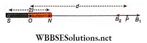
Calculation: Magnetic field at the point P due to N-pole,
⇒ \(B_1=\frac{\mu_0}{4 \pi} \cdot \frac{q_m}{(d-l)^2} ; \text { the direction of } \vec{B}_1 \text { is along } \overrightarrow{O P}\)
Again, the magnetic field at the point P due to S-the pole,
⇒ \(B_2=\frac{\mu_0}{4 \pi} \cdot \frac{q_m}{(d+l)^2} ; \text { the direction of } \vec{B}_2 \text { is along } \overrightarrow{P O}\)
∵ The N-pole is nearer to P than the S-pole, and the value of B1 is greater than that of B2.
Therefore, the resultant magnetic field at the point P,
⇒ \(B=B_1-B_2=\frac{\mu_0}{4 \pi}\left[\frac{q_m}{(d-l)^2}-\frac{q_m}{(d+l)^2}\right]\)
⇒ \(\frac{\mu_0}{4 \pi} \cdot \frac{q_m \cdot 4 d l}{\left(d^2-l^2\right)^2}\)
= \(\frac{\mu_0}{4 \pi} \cdot \frac{2 p_m d}{\left(d^2-l^2\right)^2}\) [pm = qm.21 = magnetic moment of the bar magnet]
The direction of \(\vec{B}\) is along \(\vec{OP}\).
The vector representation of the equation is,
⇒ \(\vec{B}=\frac{\mu_0}{4 \pi} \cdot \frac{2 \vec{p}_m d}{\left(d^2-l^2\right)^2}\)
The resultant magnetic intensity in the CGS system
⇒ \(H=\frac{2 p_m d}{\left(d^2-l^2\right)^2}\)
If the length of the bar magnet is very small and the point p is taken at a very- large distance from the bar magnet, l.e., d>>l, then (d²- l²)² ≈ d4.
∴ \(B=\frac{\mu_0}{4 \pi} \cdot \frac{2 p_m}{d^3}\)
| Class 11 Physics | Class 12 Maths | Class 11 Chemistry |
| NEET Foundation | Class 12 Physics | NEET Physics |
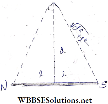
Broadside on or equatorial position:
A bar magnet SN is kept in the air, its pole strength is qm, and magnetic length = SN = 2l.
A point P is taken on the perpendicular bisector of the magnetic length and at a distance d from the mid-point O of the magnet.
The position of the point p is called the broadside-oil or equatorial position. We have to determine the magnetic field at the point P due to the magnet.
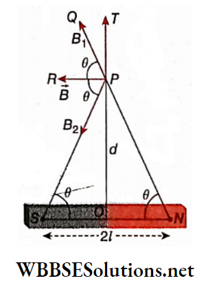
Calculation: Magnetic field at the point P due to N-pole,
⇒ \(B_1=\frac{\mu_0}{4 \pi} \cdot \frac{q_m}{N P^2} \text {; the direction of } \vec{B}_1 \text { is along } \overrightarrow{P Q}\)
Again, the magnetic field at the point P due to the S-pole,
⇒ \(B_2=\frac{\mu_0}{4 \pi} \cdot \frac{q_m}{S P^2} ; \text { the direction of } \vec{B}_2 \text { is along } \overrightarrow{P S}\)
The components of B1 and B2, i.e., B1sinθ and B2sinθ, along with PT and PO respectively, cancel each other.
On the other hand, the components B1cosθ and B2cosθ along PR are added together.
So, the resultant magnetic field at the point P,
B = 2B1cosθ [∵ magnitudes of B1 , B2 are equal]
or, \(B=\frac{2 \mu_0}{4 \pi} \cdot \frac{q_m}{N P^2} \cos \theta=\frac{2 \mu_0}{4 \pi} \cdot \frac{q_m}{\left(d^2+l^2\right)} \cdot \frac{l}{\sqrt{d^2+l^2}}\)
⇒ \(\frac{\mu_0}{4 \pi} \cdot \frac{p_m}{\left(d^2+l^2\right)^{3 / 2}} \text {; the direction of } \vec{B} \text { is along } \overrightarrow{P R}\)
The vector representation of the equation is,
⇒ \(\vec{B}=-\frac{\mu_0}{4 \pi} \cdot \frac{\vec{p}_m}{\left(d^2+l^2\right)^{3 / 2}}\)
The resultant magnetic intensity in the CGS system,
⇒ \(H=\frac{p_m}{\left(d^2+l^2\right)^{3 / 2}}\)
If the length of the bar magnet is very small and the point P is
taken at a very large distance from the bar magnet, i.e., l<<d
then, \(B=\frac{\mu_0}{4 \pi} \cdot \frac{p_m}{d^3}\)
So, magnetic field at the end-on or axial position = 2 x magnetic field at the broadside-on or equatorial position
Magnetic Properties notes for Class 12 WBCHSE Any position:
Concerning the bar magnet of magnetic length 2l, the point P under consideration is at the position (r, θ), i.e., the point P is at a distance r from the mid-point of the magnet and lies at an angle θ with the magnetic axis.
The component of pm along r is pmcosθ; concerning this component, the point P is at the end of the position, and hence the magnetic field at the point P,
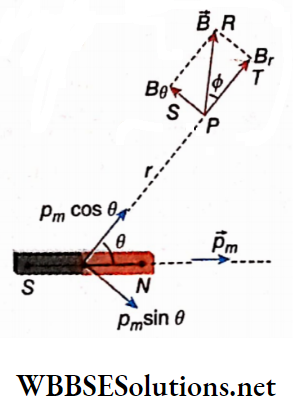
⇒ \(B_r=\frac{\mu_0}{4 \pi} \cdot \frac{2 p_m \cos \theta}{r^3}(∵ r \gg l)\)
Again, the component of pm normal to r is pmsinθ; concerning this component point P is at the equatorial position, and hence the magnetic field at point P,
⇒ \(B_\theta=\frac{\mu_0}{4 \pi} \cdot \frac{p_m \sin \theta}{r^3}\)
So, according to the resultant magnetic field at the point P,
⇒ \(B=\sqrt{B_r^2+B_\theta^2}=\sqrt{\left(\frac{\mu_0}{4 \pi} \cdot \frac{p_m}{r^3}\right)^2\left(4 \cos ^2 \theta+\sin ^2 \theta\right)}\)
⇒ \(\frac{\mu_0}{4 \pi} \cdot \frac{p_m}{r^3} \sqrt{3 \cos ^2 \theta+1}\)
The direction of \(\vec{B} \text { is along } \overrightarrow{P R} \text {; where } \angle T P R=\phi \text { (say) }\)
∴ \(\tan \phi=\frac{B_\theta}{B_r}=\frac{1}{2} \tan \theta\)
The resultant magnetic intensity in the CGS system,
⇒ \(H=\frac{p_m}{r^3} \sqrt{3 \cos ^2 \theta+1}\)
Equivalence of a solenoid and a bar magnet: Let us assume a solenoid of radius = a, length = 2l, number of turns per unit length = n. Current through it = I.
So, the total number of turns of the solenoid = 2ln, and hence the effective net current around its axis =2lnI. As the cross-sectional area of the solenoid = πa², so, the magnetic dipole moment of the current-carrying solenoid,
⇒ \(p_m=(2 \ln I) \cdot\left(\pi a^2\right)=2 \pi \ln a^2 I\)
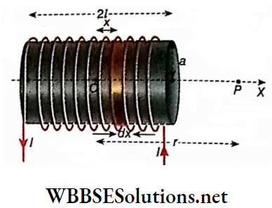
Now the center (O) of the solenoid is taken as the origin and its axis as the x-axis. Considering a small length dx at a distance x from 0, we get a circular current-carrying coil with several turns dx. For this coil, the magnetic field is thus produced at a point P on the axis (where, OP = r and r>>a, r>>x),
⇒ \(d B=\frac{\mu_0(n d x) I}{2} \cdot \frac{a^2}{\left\{a^2+(r-x)^2\right\}^{3 / 2}}=\frac{\mu_0 n I a^2}{2 r^3} d x\) [As a and x are negligible with respect to r, \(\left\{a^2+(r-x)^2\right\}^{3 / 2} \approx r^3\)]
So, the magnetic field at P for the entire solenoid,
⇒ \(B=\frac{\mu_0 n I a^2}{2 r^3} \int_{-l}^l d x=\frac{\mu_0 n I a^2}{2 r^3} \cdot 2 l=\frac{\mu_0}{4 \pi} \cdot \frac{2\left(2 \pi \ln a^2 I\right)}{r^3}\)
i.e., \(B=\frac{\mu_0}{4 \pi} \frac{2 p_m}{r^3}\)
In this very section, we have already found the same expression due to a bar magnet. Thus we conclude that a bar magnet and a current-carrying solenoid are equivalent to each other.
Comparing their magnetic moments, we get,
⇒ \(q_m \cdot 2 l=2 \pi \ln a^2 I \quad \text { or, } q_m=\pi n a^2 I\)
Magnetic Properties Notes For Class 12 WBCHSE
Magnetic Moment of Charged Particle Moving in a Circle:
We know that a revolving charged particle is equivalent to an electric current. So, the orbit of that particle is equivalent to a current loop and as a result, it behaves as a magnetic dipole which must have a magnetic moment.
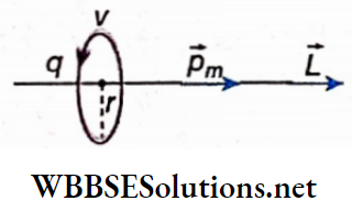
Suppose a particle having a charge q is revolving in a plane circular path; r = radius of the orbit of that particle and v = velocity of the particle.
The period of revolution of the particle, \(T=\frac{2 \pi r}{v}\)
∴ Equivalent current, \(I=\frac{q}{T}=\frac{q v}{2 \pi r}\)
So, the magnetic moment of the particle,
⇒ \(p_m=\frac{q \nu}{2 \pi r} \cdot A=\frac{q \nu}{2 \pi r} \cdot \pi r^2=\frac{q v r}{2}\)
The direction of this magnetic moment pm can be obtained by applying a corkscrew rule. If the mass of the particle is m then along the axis of the circular path, Le., along the direction of pm, the angular momentum of the particle,
L = mv [L = moment of momentum = momentum x radius of circular path]
∴ \(p_m=\frac{q v r}{2}=\frac{q}{2 m} \cdot m v r=\frac{q}{2 m} L\)
Since the directions of pm and L are the same, using vector notation we can write,
⇒ \(\vec{p}_m=\frac{q}{2 m} \vec{L}\)…(1)
Magnetic dipole moment of an electron:
Electrons inside an atom revolve around the nucleus continuously. As a revolving charged particle, each electron behaves as a magnetic dipole. Substituting the charge of an electron -e in place of q in equation (1), we can write,
⇒ \(\vec{p}_m=-\frac{e}{2 m} \cdot \vec{L}\)…(2)
The negative sign on the right-hand side indicates that the charge of an electron is negative, its angular momentum and magnetic moment are oppositely directed.
From Bohr’s theory related to atomic structure: Atoms, it is known that electrons revolving in different orbits have discrete angular momenta, defined as
⇒ \(L=n \frac{h}{2 \pi}=n \hbar \quad[n=1,2,3, \cdots]\)
Here, \(h=\text { Planck’s constant }=6.626 \times 10^{-34} \mathrm{~J} \cdot \mathrm{s} \text { and } \dot{\hbar}=\frac{h}{2 \pi}\)
= 1.05 x 10⁻³⁴ J.s = reduced Planck’s constant
So, the magnitude of the magnetic moment of an electron [from equation (2)],
⇒ \(p_m=\frac{e}{2 m} n \hbar=n \frac{e \hbar}{2 m}\)….(3)
In the case of the innermost orbit of an atom (K-orbit), n = 1; then \(p_m=\frac{e \hbar}{2 m}\) – this quantity is called Bohr magneton. It is denoted by μB and it is the atomic unit of the magnetic moment
⇒ \(I \mu_B=\frac{e h}{2 m}=\frac{\left.\left(1.6 \times 10^{-19} \mathrm{C}\right) \times\left(1.05 \times 10^{-34}\right) \cdot s\right)}{2 \times\left(9.1 \times 10^{-31} \mathrm{~kg}\right)}\)
= 9.23 x 10⁻²⁴ A m2
= 9.23 x 10⁻²⁴ J. T-1
The spin of an electron: Besides the revolution of each electron in its orbit, it also rotates about its axis (like the diurnal motion of the earth). This is known as the spin of an electron. An electron may have any of two oppositely directed spins.
One kind of spin (say clockwise) is called up spin and is denoted by ( symbol) The opposite kind of spin is then known as down spin and is denoted by the symbol.
Due to the spin of any electron. a magnetic moment generates. By theoretical analysis, its Value is found to be l Bohr magneton. It is allied tire intrinsic spin magnetic moment.
The concept of rotation of an electron about its axis is oversimplified and requires quantum physics for a proper explanation.
The magnetism of an atom: If the resultant moment i.e., the vector sum of tire magnetic moments of the electrons rotating, around the nucleus inside an atom is zero, we can say that the atom as a whole does not show the airy magnetic property.
On the other hand, if the resultant is not zero, the tire atom behaves like a magnetic dipole. Due to this property, each atom or molecule of iron, nickel eta behaves like a small magnet and is called an atomic magnet.
Magnetic Properties Notes For Class 12 WBCHSE
Magnetic Properties Of Materials Numerical Examples
Example 1. A torque of 8 units is applied on a magnet when it is kept at 30° with the direction of a uniform magnetic field of intensity 0.32 units. Determine the magnetic moment of the magnet.
Solution:
If a magnet having magnetic moment pm is placed inclined at an angle θ with a uniform magnetic field B, the torque acting on the magnet,
⇒ \(\tau=p_m B \sin \theta\)
Here, B = 0.32 units, θ = 30° and \(\tau\) = 8 units.
∴ \(p_m=\frac{\tau}{B \sin \theta}=\frac{8}{0.32 \times \sin 30^{\circ}}\)
⇒ \(\frac{8}{0.32 \times \frac{1}{2}}=50 \text { units }\)
Practice Problems on Magnetization
Example 2. lf the distance between two north poles of equal strength is 2 cm, the mutual force of repulsion between them becomes 2.5 dyn. What should be the distance of separation between them for which the repulsive force becomes 3.6 dyn?
Solution:
Magnetic force between two magnetic poles,
⇒ \(F=\frac{\mu_0}{4 \pi} \cdot \frac{q_m \cdot q_m^{\prime}}{r^2}\)
So, if the pole strength remains unchanged then, \(F \propto \frac{1}{r^2}\)
Hence, for two separate distances,
⇒ \(\frac{F_1}{F_2}=\left(\frac{r_2}{r_1}\right)^2 \quad \text { or, } \frac{r_2}{r_1}=\sqrt{\frac{F_1}{F_2}}\)
∴ \(r_2=r_1 \sqrt{\frac{F_1}{F_2}}=2 \times \sqrt{\frac{2.5}{3.6}}=2 \times \frac{5}{6}\)
= 1.67cm
Example 3. The length of a bar magnet is 20 cm and its magnetic moment is 0.6 Am2. Determine the magnetic field at a point 30 cm away from either end.
Solution:
PN = PS
= 30 cm
= 0.3 m
= \(\sqrt{d^2+l^2}\)
The magnetic field at the point P due to the magnet,
⇒ \(B=\frac{\mu_0}{4 \pi} \cdot \frac{p_m}{\left(d^2+l^2\right)^{3 / 2}}\)
⇒ \(\frac{4 \pi \times 10^{-7}}{4 \pi} \times \frac{0.6}{(0.3)^3}\)
= 2.22 x 10⁻⁶ Wb.m-2
Example 4. The length of a bar magnet is 20 cm and its magnetic moment is 0.6 A.m2. Determine the magnetic field at a point on the axis of the magnet and 30 cm away from the north pole.
Solution:
Length of the magnet. 2l = 20 cm
= 0.2 m
So, l = 0.1 m
Distance of the given point from the center of the magnet,
d = (0.3 + 0.1)m
= 0.4 m
∴ The magnetic field at the given point due to the magnet,
⇒ \(B=\frac{\mu_0}{4 \pi} \cdot \frac{2 p_m d}{\left(d^2-l^2\right)^2}=\frac{4 \pi \times 10^{-7}}{4 \pi} \times \frac{2 \times 0.6 \times 0.4}{\left\{(0.4)^2-(0.1)^2\right\}^2}\)
⇒ \(10^{-7} \times \frac{0.48}{0.0225}=2.13 \times 10^{-6} \mathrm{~Wb} \cdot \mathrm{m}^{-2}\)
WBCHSE Class 12 Physics Chapter 6 solutions
Example 5. The radius of a circular conducting coil of 100 turns Is 10 cm. If 2A current passes through the coil, what will be the magnetic moment generated?
Solution:
Magnetic moment,
pm = NIA = NIπr2
= 100 x 2 x (π x 0.1 x 0.1) [∵ 10 cm = 0.1 m]
= 6.28 A.m2
Example 6. If the magnetic moment of a straight magnetized wire is pm, what will be Its magnetic moment when the wire is bent in the form of a semicircle?
Solution:
Let the length of the magnetized wire be l.
∴ Pole-strength of the wire, \(m=\frac{p_m}{l}\)
When the wire is bent in the form of a semicircle, its effective length = diameter of the semicircle = 2r.
According to the problem, \(\pi r=l \quad \text { or, } r=\frac{l}{\pi}\)
∴ The changed magnetic moment of the wire = effective length x pole-strength
⇒ \(2 r \times \frac{p_m}{l}=\frac{2 l}{\pi} \cdot \frac{p_m}{l}=\frac{2 p_m}{\pi}\)
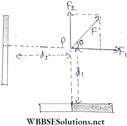
Example 7. The magnetic moments of two small magnets are pm and p’m; they are kept on a table. What will be the magnitude and direction of the magnetic field produced by the gents at point P? [pm = 2.7 A m2, pm = 3,2 A m2; d1 = 30 cm, d2 = 40 cm]
Solution:
According to the point, P lies on the perpendicular bisectors of both magnets.
The magnetic field at the point P due to the magnet having magnetic moment pm,
⇒ \(B_1=\frac{\mu_0}{4 \pi} \cdot \frac{p_m}{d_1^3}=10^{-7} \times \frac{2.7}{(0.3)^3}=10^{-5} \mathrm{~T}\)
At point P, the magnetic field due to the magnet having magnetic moment I’m is,
⇒ \(B_2=\frac{\mu_0}{4 \pi} \cdot \frac{p_m^{\prime}}{d_2^3}=10^{-7} \times \frac{3.2}{(0.4)^3}=5 \times 10^{-6} \mathrm{~T}\)
Since these two magnetic fields are perpendicular to each other, the resultant magnetic field at the point P,
⇒ \(B=\sqrt{B_1^2+B_2^2}\)
⇒ \(\sqrt{\left(10^{-5}\right)^2+\left(5 \times 10^{-6}\right)^2}\)
= 1.12 x 10⁻⁵T
If the resultant magnetic field makes an angle θ with B1, then,
⇒ \(\tan \theta=\frac{B_2}{B_1}=\frac{5 \times 10^{-6}}{10^{-5}}=0.5\)
∴ \(\theta=\tan ^{-1}(0.5)=26.57^{\circ}\)
Conceptual Questions on Magnetic Field Lines
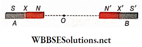
Example 8. Two bar magnets A and B, each having a magnetic length of 4 cm are placed along a straight line with their north poles 8 cm apart and facing each other. The neutral point lies on the axis, 2 cm from the north pole of the magnet A. Calculate the ratio of the magnetic moments of A and B.
Solution:
O is die neutral point.
Given, NO = 2 cm
N’O = (8-2)
= 6 cm
⇒ \(X N=X^{\prime} N^{\prime}=l=\frac{4}{2} \mathrm{~cm}=2 \times 10^{-2} \mathrm{~m}\)
d1 = XO
= (2 + 2) cm
= 4 x 10⁻³ m
d2 = X’O
= (6 + 2) cm
= 8 x 10⁻³ m
∴ The magnetic field at point O due to the magnet A,
⇒ \(B_1=\frac{\mu_0}{4 \pi} \frac{2 p_{m_1} d_1}{\left(d_1^2-l^2\right)^2}\)
or, \(B_1=\frac{\mu_0}{4 \pi} \frac{2 p_{m_1} \times 4 \times 10^{-2}}{\left[\left(4 \times 10^{-2}\right)^2-\left(2 \times 10^{-2}\right)^2\right]^2}\)
⇒ \(=\frac{\mu_0}{4 \pi} \cdot \frac{2 p_{m_1} \times 4 \times 10^{-2}}{(16-4)^2 \times 10^{-8}}\)
∴ The magnetic field at O due to the magnet B,
⇒ \(B_2=\frac{\mu_0}{4 \pi} \frac{2 p_{m_2} \times 8 \times 10^{-2}}{\left[\left(8 \times 10^{-2}\right)^2-\left(2 \times 10^{-2}\right)^2\right]^2}\)
⇒ \(\frac{\mu_0}{4 \pi} \cdot \frac{2 p_{m_2} \times 8 \times 10^{-2}}{(64-4)^2 \times 10^{-8}}\)
According to the question, B1 = B2
∴ \(\frac{\mu_0}{4 \pi} \cdot \frac{2 p_{m_1} \times 4 \times 10^{-2}}{144 \times 10^{-8}}=\frac{\mu_0}{4 \pi} \cdot \frac{2 p_{m_2} \times 8 \times 10^{-2}}{3600 \times 10^{-8}}\)
or, \(\frac{p_{m_1}}{p_{m_2}}=\frac{2 \times 144}{3600}=\frac{2}{25}\)
∴ Ratio of the magnetic moments \(p_{m_1}: p_{m_2}=2: 25\)
WBCHSE Class 12 Physics Chapter 6 Solutions
Magnetic Properties Of Materials Magnetic Lines Of Induction
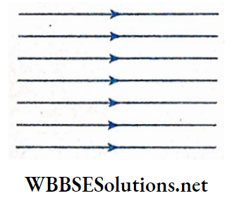
The magnetic lines of force in a uniform magnetic field are equidistant parallel straight lines.
If a piece of any magnetic material (i.e., iron, steel, nickel, etc.) is placed in this kind of external magnetic field, a magnetic field is induced in the specimen which is converted into a temporary magnet. The external magnetic field is referred to as the inducing magnetic field.
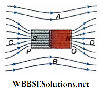
Let an iron bar PQ be placed parallel to a uniform magnetic field. At the end of PQ through which the magnetic lines of force enter, an S-pole is developed and at the other end, an AT-pole is developed.
So, due to induction, the magnetic lines of force are rearranged. This rearrangement inside and outside the magnetic material is discussed below.
The lines inside the magnetic material are generated due to the superposition of two kinds of lines of force:
- The lines of force are due to the inducing magnetic field.
- The lines of magnetization (the magnetic material is temporarily converted into a magnet due to induction and the lines of the magnetic field of this temporary magnet are called lines of magnetization).
The lines of force outside the magnetic material are generated due to the superposition of two types of lines of force:
- The lines of force due to inducing magnetic field
- The lines of force are due to the temporary magnetic field of the magnetized specimen.
Outside the iron bar, the lines of force suffer bending and inside the bar are densely crowded. In the region adjacent to points A and B outside the iron bar, the lines of force are less dense.
Note that, inside the bar PQ, the lines of force of the inducing field and the lines of magnetization are unidirectional. It means that inside the bar PQ, the resultant of the two magnetic fields increases, and hence in that region and the adjacent regions C and D, the lines of force are densely crowded.
In the regions adjacent to points A and B, the inducing magnetic field and the temporary magnetic field are oppositely directed and hence the resultant magnetic field decreases there. So the lines of force become less dense in that region
Definition:
The lines of force generated inside a magnetic material due to the superposition of the lines of force of the inducing magnetic field and the lines of magnetization are called the lines of induction.
Outside a magnetic material lines of magnetic induction follow magnetic lines of force. In some materials, called diamagnetic materials, the scenario would be the reverse of the above picture
Magnetic Properties Of Materials Some Magnetic Quantities And Their Relations
Magnetic permeability of a material:
Let the current through a long straight solenoid = I; the number of turns per unit length of the solenoid = n.
If air or vacuum is taken as the core of the solenoid, the magnetic field produced along the axis of the solenoid,
B0 = μ0nI…(1)
where, μ0 = magnetic permeability of vacuum (or air)
= 4π x 10-7 H.m-1
If a rod of any material is introduced inside the solenoid co-axially, the magnetic field along the axis of the solenoid will change; this magnetic field can be expressed as,
B = μnI….(2)
This quantity ju is called the magnetic permeability of the material used.
Relative magnetic permeability: If air or vacuum is replaced by a material, the fractional change of magnetic field in that material is called the relative magnetic permeability of that material.
So, relative magnetic permeability,
⇒ \(\mu_r=\frac{B}{B_0}=\frac{\mu n I}{\mu_o n I}=\frac{\mu}{\mu_0}\)….(3)
Unit: Equations (1) and (2) show that the units of μ0 are the same, i.e., H m-1.
Again, equation (3) shows that being the ratio of two identical quantities μ and μ0, μr has no unit.
Classification of materials: Depending on the value of relative magnetic permeability μr, different materials can be divided into three groups.
1. \(\mu_r<1 \text {, i.e., } \mu<\mu_0\): Diamagnetic material;
2. \(\mu_r>1 \text {, i.e., } \mu>\mu_0\): Paramagnetic material;
3. \(\mu_r \gg 1 \text {, i.e., } \mu \gg \mu_0\): Ferromagnetic material.
For Example, in the case of aluminum, μr = 1.00002, hence it is a paramagnetic material; in the case of copper, μr = 0.9999904, hence it is a diamagnetic material; in the case of iron, μr = 1000 to 5000 (approx.), hence it is a ferromagnetic material. These materials are discussed elaborately later
Magnetization: If the magnetizing field at any point in vacuum or air is \(\vec{B}\), the magnetic field at that point, \(\vec{B}_0=\mu_0 \vec{H}\).
If vacuum or air at a point is replaced by any other material, magnetism is induced in that material and hence the magnetic field acting will also change from \(\vec{B}_0 \text { to } \vec{B}\) (say).
Naturally, \(\vec{B} \neq \mu_0 \vec{H}\). If the material is paramagnetic or ferromagnetic, \(\vec{B}>\mu_0 \vec{H}\). Here, it is assumed that,
⇒ \(\vec{B}=\mu_0 \vec{H}+\mu_0 \vec{M}=\mu_0(\vec{H}+\vec{M})\)….(4)
The first term on the right-hand side \(\left(\mu_0 \vec{H}\right)\) comes from the magnetizing field \(\vec{H}\) produced because of electric current or some other external cause, and tire second term \(\left(\mu_0 \vec{M}\right)\) comes due to induced magnetism inside the material.
So, the term \(\mu_0 \vec{M}\) indicates the additional magnetic field produced due to magnetic induction.
The quantity \(\vec{M}\) is called the intensity of magnetization of the material or simply the magnetization vector, the magnitude of which at a point is given as the net dipole moment per unit volume around that point.
By calculation, we can show that (this calculation is omitted here), the magnetic moment per unit volume of a material is \(\vec{M}\).
Definition: If the unit volume is considered around any point in a material, the magnetic moment of that volume is called the intensity of magnetization at that point. So, relative magnetic permeability
Unit: From equation (4) it is clear that the unit of \(\vec{M}\) is the same as the unit of \(\vec{H}\).
This unit is A.m-1. \(\vec{B}\), \(\vec{H}\) and \(\vec{M}\) are called the three magnetic vectors,
Magnetic susceptibility of material: In most materials, the intensity of magnetization at a point is directly proportional to the magnetic intensity at that point, i.e.,
⇒ \(M \propto H \quad \text { or, } M=k H\)
This constant fc is called the magnetic susceptibility of the material. The property by which a material can be magnetized is its magnetic susceptibility.
In vector form, \(\vec{M}\) = k\(\vec{H}\)….(5)
Now, if H = 1, k = M; from this we can define k.
Important Definitions in Magnetism
Definition: The magnetic moment induced per unit volume of a material due to unit magnetic intensity is called the magnetic susceptibility of that material.
Unit: Since the units of M and H are the same, k has no unit.
Mass (magnetic) susceptibility: The ratio of the magnetic susceptibility of a material and its density is called the mass susceptibility of that material. It Is denoted by the symbol \(\chi\).
∴ Mass susceptibility,
⇒ \(x=\frac{k}{\rho}\) [where, ρ = density of the material]
Rotation between magnetic susceptibility and relative magnetic permeability:
We know that,
⇒ \(\vec{B}=\mu \vec{H}\)
⇒ \(\vec{B}=\mu_0(\vec{H}+\vec{M}) \text { and } \vec{M}=k \vec{H}\) [from equations (4) and (5)]
Combining them we can write,
⇒ \(\mu \vec{H}=\mu_0(\vec{H}+\vec{M})=\mu_0(\vec{H}+k \vec{H})=\mu_0(1+k) \vec{H}\)
∴ \(\frac{\mu}{\mu_0}=1+k \quad \text { or, } \mu_r=1+k\) [\(\mu_r=\frac{\mu}{\mu_0}\) = relative magnetic permeability]
or, k = μr – 1….(6)
For vacuum or air, μr = 1 , hence, k = 0
The values of μr and k of some materials:
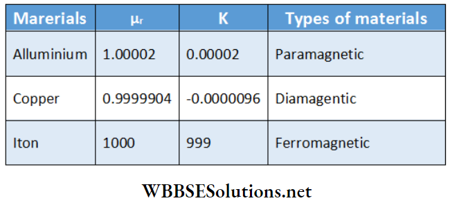
Hence, for paramagnetic material, k > 0 (positive); for diamagnetic material, k<0 (negative); for ferromagnetic material, k >> 0 (large positive number).
Significance:
1. In the case of paramagnetic and diamagnetic materials magnetic susceptibilities are very low and are respectively positive and negative numbers.
This means that magnetic induction in these materials is negligible. Thus, these are called non-magnetic materials.
2. On the other hand, in the case of ferromagnetic materials magnetic susceptibilities are large positive numbers.
Hence, in this kind of material, strong magnetic induction takes place. Thus, these are known as magnetic materials (e.g., iron, nickel, cobalt).
Since the value of k is very large, from the relation, \(\vec{B}=\mu_0(\vec{H}+\vec{M})=\mu_0(\vec{H}+k \vec{H})\), we come to know that the term pgM is much greater than the term p0H.
So, the magnitude of the magnetic field \(\vec{B}\) is mainly determined by induced magnetism.
In CGS or Gaussian system:
Equations (l) and (2) respectively, can be replaced by the relations, H0 = 4π ni [magnetic permeability of vacuum or air =1 ] and H = 4πμni [magnetic permeability of the material = μ] So, relative magnetic permeability, \(\mu_r=\frac{H}{H_0}=\mu\); so in this system, magnetic permeability and relative magnetic permeability of a material are the same.
Again, in this system equation (4) is written as,
⇒ \(\vec{B}=\vec{H}+4 \pi \vec{M}\)
But we know that, \(\vec{B}=\mu \vec{H}\)
So, \(\mu \vec{H}=\vec{H}+4 \pi k \vec{H} \quad[∵ \vec{M}=k \vec{H}]\)
⇒ \(\mu=1+4 \pi k \quad \text { or, } k=\frac{\mu-1}{4 \pi}\)
Magnetic retentivity and coercivity:
When a magnetic material is placed in a magnetic field, the material acquires magnetism due to induction. This magnetism does not vanish completely even after the withdrawal of the magnetic field; some amount of magnetism is left behind in the material.
Magnetic retentivity:
The property by which a magnetic material retains some magnetism in it even after the withdrawal of the magnetizing field is called the retentivity of that material.
The magnetism, retained in a magnetic material even after the removal of the magnetic field applied to it, is called residual magnetism.
There are some magnetic materials for which the residual magnetism is almost zero, i.e., they are almost completely demagnetized.
Magnetic coercivity: The property by which magnetic material can retain induced magnetism even if used roughly, i.e., subjected to demagnetizing forces, is called the coercivity of that material.
Differences between wrought iron and steel on magnetic properties:
If two identical rods one of soft iron and the other of steel-are placed in the same magnetic field, both of them acquire approximately equal amounts of magnetism.
If the rods are then removed from the magnetic field, both soft iron and steel retain almost the entire magnetism.
Soft iron can hold slightly more magnetism than steel. But if this soft iron magnet is handled roughly, its magnetism dies out easily compared to that of steel.
So, it can be said that the magnetic retentivity of soft iron is slightly greater, but the coercivity of soft iron is much less than that of steel.
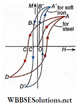
A ferromagnetic material can be converted into a strong magnet easily. In the case of a ferromagnetic material like soft iron or steel, if a graph of intensity of magnetization (M) vs magnetic field intensity (H) is drawn, we will get a closed loop.
It is known as the magnetization cycle. In the case of steel, the loop is OABCDA and in the case of soft iron, the loop is OA’B’C’D’A’. From the graph, it is evident that the intensity of magnetization (M) is not zero ( OB or OB’) even if the magnetic field intensity (H) is reduced to zero from its maximum value, i.e., M lags behind H.
This lagging of the intensity of magnetization is called hysteresis. However, M falls to zero if H is given a certain value (OC or OC’) in the opposite direction. According to the diagram, OB is the retentivity of steel, OB’ is the retentivity of soft iron, OC is the coercivity of steel, and OC’ is the coercivity of soft iron.
Selection of material to construct a permanent magnet:
The magnetic material chosen to construct a permanent magnet should have the following properties m The material should have high retentivity so that it can retain sufficient magnetism even after the withdrawal of the magnetizing field.
If The saturation magnetization of the material should be high enough it can make a strong polarity.
The material should also have high coercivity so that it can retain induced magnetization, even if used roughly. The magnetic susceptibility of the material should be of high magnitude.
Though all of the above properties do not match properly, steel, rather than soft iron is used to construct permanent magnets.
Besides steel, there are some metallic alloys like alnico (Fe 51%, Cu 3%, A1 8%, Ni 14%, Co 24% ); national (Fe 47%, Cu 3%, A1 8%, Ti 2%, Ni 15%, Co 25% ), etc. possess the above-mentioned qualities and can be used to construct permanent magnets.
Selection of material to construct an electromagnet: To construct an electromagnet, a material that possesses the following properties should be chosen.
1. The material should have low retentivity so that it can lose almost all of its magnetism as soon as the applied magnetizing field is withdrawn.
2. The saturation magnetisation of the material should be high enough which can make a strong polarity.
3. The material must have low coercivity so that it can be easily demagnetized.
4. Hysteresis loss for the material should be low so that during magnetization and demagnetization the temperature of the material should remain more or less constant.
Soft iron or alloy (an alloy of 5% silicon and 95% iron) possesses these qualities and hence can be used as the core of an electromagnet.
Selection of material as the core of a transformer or dynamo:
To prepare the core of a transformer or a dynamo, a high magnetic permeability material should be chosen.
Soft iron possesses such qualities, and hence it is used as the core. Moreover, metallic alloys, like permalloy (50% iron and 50% nickel) and transformer steel (96% iron and 4% silicon), are used nowadays for the same purpose.
Magnetic Properties Of Materials Numerical Examples
Example 1. The number of turns of a solenoid of length 10 cm is 1000. If the air inside it is replaced by a magnetic material and 1 A current is passed through the coil, the magnitude of the magnetic field at any point on its axis becomes 20 T. Determine the magnetic Intensity at that point and relative magnetic permeability of the magnetic material.
Solution:
Number of turns per unit length of the coil,
⇒ \(n=\frac{1000}{10}=100 \mathrm{~cm}^{-1}=10000 \mathrm{~m}^{-1}\)
∴ Magnetic intensity on the axis
H = nI = 10000 x 1
= 10000 A.m-1
If the interior of the solenoid is a vacuum or contains air then the magnetic field on the axis,
B0 = μ0nI = (4π x 10-7) x 10000 = 12.56 x 10⁻³T
Due to the presence of the magnetic material,
B = μnl = 20 T
∴ Relative magnetic permeability,
⇒ \(\mu_r=\frac{\mu}{\mu_0}=\frac{B}{B_0}=\frac{20}{12.56 \times 10^{-3}}=1592\)
Example 2. The relative magnetic permeability of a magnetic medium is 1000. If the magnetic field at any point in the medium is 0.1 Wb.m-2, what will be the values of magnetic intensity and intensity of magnetization at that point?
Solution:
Here, B = 0.1 Wb.m-2 and μr – 1000.
So, μ = μ0 x μr
= 4π x 10-7 x 1000
= 4π x 10-4 H.m-1
Now, magnetic intensity, \(H=\frac{B}{\mu}=\frac{0.1}{4 \pi \times 10^{-4}}=79.6 \mathrm{~A} \cdot \mathrm{m}^{-1}\)
Again, B = μ0(H + M)
∴ The intensity of magnetization,
⇒ \(M=\frac{B}{\mu_0}-H=\frac{0.1}{4 \pi \times 10^{-7}}-79.6\)
= 79577.5 – 79.6
= 79497.9 A.m-1
Real-Life Scenarios in Magnetic Properties Experiments
Example 3. An iron-cored toroid has a ring radius of 7 cm and several turns of 500. If 2 A current is passed through the wire, what will be the value of a magnetic field on the axis of the toroid? Given, the relative magnetic permeability of iron = 1500.
Solution:
Length of the circular axis of the ring
⇒ \(2 \pi r=2 \times \frac{22}{7} \times 7=44 \mathrm{~cm}=0.44 \mathrm{~m}\)
∴ The number of turns per unit length of the toroid,
⇒ \(n=\frac{500}{0.44} \mathrm{~m}^{-1}\)
∴ Magnetic field on the axis of the toroid,
B = μ0nI
= μ0μrnI
⇒ \(\left(4 \pi \times 10^{-7}\right) \times 1500 \times \frac{500}{0.44} \times 2=4.28 \mathrm{~Wb} \cdot \mathrm{m}^{-2}\)
WBCHSE Class 12 Physics Chapter 6 Solutions
Magnetic Properties Of Materials Paramagnetic Diamagnetic And Ferromagnetic Materials
Depending on the behavior of a material placed in an external magnetic field.
Michael Faraday first classified all materials into three groups:
- Paramagnetic material,
- Diamagnetic material
- Ferromagnetic material.
Paramagnetic Material:
The materials attracted feebly by a strong magnet are known as paramagnetic materials. Paramagnetic materials may be solid, liquid, or gaseous.
Examples: Solid elements like aluminum, potassium, platinum, sodium, tin, manganese, etc., copper sulfate, ferric chloride salts and their aqueous solutions, and gaseous materials like oxygen, air, etc.
The relative magnetic permeability of a paramagnetic material varies from 1 to 1.001 and its magnetic susceptibility has a very small positive value (10-4 or less).
Properties:
1. When a paramagnetic material is placed in a non-uniform magnetic field, it moves gradually from the weaker part to the stronger part of that magnetic field, i.e., the material is attracted feebly by the magnet
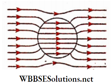
2. If a paramagnetic material is placed in a uniform magnetic field, the lines of force close up a little and pass through the material. As a result, the lines inside that material get crowded slightly.
So, the magnetic field (B), increases slightly inside a paramagnetic material.
3. A small number of molecules of a paramagnetic material are magnetic dipoles. When heated, the random thermal motion of these dipoles increases, and hence their magnetic alignment is disturbed. As a result, both magnetic susceptibility and magnetic permeability decrease.
Magnetic susceptibility per unit mass of a paramagnetic material, \(\chi=\frac{k}{\rho}(\rho=\text { density })\) is inversely proportional to the absolute temperature; i.e., \(\chi=\frac{C}{T}\) (for a particular material C is constant).
This is known as Curie law. Experimental observations show that Curie’s law applies only to gases. In the case of paramagnetic solids, Curie- Weiss law is applicable.
According to this law,
Magnetic susceptibility \(\chi=\frac{C}{T-\theta}\)
where θ is a specific temperature known as the Curie temperature of that paramagnetic material. The values of Curie temperature are very small for almost all paramagnetic materials.
4. If a liquid is poured through one of the limbs of a vertical U-tube then the liquid rises to the same level in both limbs.
If the liquid is paramagnetic and if one of the limbs of the U-tube is placed between the two poles of a strong electromagnet, it is observed that the liquid rises in that limb. This is due to the attraction of paramagnetic liquid by a magnet.

Diamagnetic Material:
The material repelled feebly by strong magnets are known as diamagnetic materials. Diamagnetic materials may be solid, liquid, or gaseous.
Examples: Antimony, bismuth, zinc, copper, silver, gold, lead, mercury, water, hydrogen, etc.
The relative permeability of a diamagnetic material is slightly less than 1 and its magnetic susceptibility is slightly negative (≥ -10-4).
Properties:
1. If a diamagnetic material is placed in a non-uniform magnetic field, it tries to move from the stronger region to the weaker region of the magnetic field. So, the material is fully repelled by a magnet.
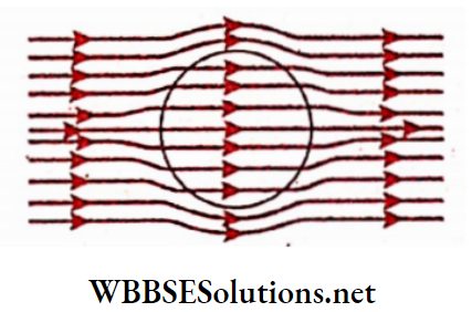
2. If a diamagnetic, material is kept in a uniform magnetic field, the lines of force move away a little. As a result, the lines are more sparse inside the material than outside. For a sphere.
So, the magnetic field (B) decreases slightly inside a diamagnetic material.
3. In a diamagnetic material, almost none of the molecules are magnetic dipoles. So the random molecular motion due to increasing temperature has a negligible effect on the magnetic properties.
An increase in the applied magnetic field also does not affect the magnetic alignment of molecules.
As a result, the magnetic susceptibility of a diamagnetic material does not depend on the applied magnetic field and temperature.
4. Theoretically it is proved that diamagnetism is present in every material. The diamagnetic property of a material is very much weaker than its paramagnetic and ferromagnetic properties.
As a result, despite the magnetic properties present in paramagnetic and ferromagnetic materials, diamagnetism remains dormant in them. Hence, it can be said that diamagnetism is the most fundamental magnetic property.
5. If some diamagnetic liquid is poured into a U-tube and if one of the limbs is now placed between the pole pieces of a strong magnet, the level of the liquid in the limb falls. This is due to the repulsion of diamagnetic liquid by the magnet.
Class 12 WBCHSE Physics Magnetic Properties concepts Ferromagnetic Material:
Five metals iron (Fe), nickel (Ni), cobalt (Co), gadolinium (Gd), dysprosium (Dy), and alloys like steel, etc. are attracted strongly by any magnet. Even if the inducing magnetic field is removed, these materials can retain some induced magnetism. These are known as ferromagnetic materials.
The relative magnetic permeability of a ferromagnetic material is usually very high (102 to 106 ) and its magnetic susceptibility is also very high and positive (200 to 2000 approximately).
Though the magnetic properties of ferromagnetic materials are just like that of paramagnetic materials they show stronger paramagnetism and hence they are placed in a separate group.
Heusler alloy is a special kind of ferromagnetic material because none of its components (Cu, 64%, Mn 24%, A1 12% ) are ferromagnetic.
Properties:
1. Generally, ferromagnetic materials are solid and crystalline.
2. If a ferromagnetic material is placed in a non-uniform field, it moves very fast from the weaker to the stronger region of the field and sets itself parallel to the direction of the magnetic field. So, ferromagnetic materials are very strongly attracted by a magnet.
If a ferromagnetic material is placed in a uniform magnetic field, the lines of force crowd too much within the material than in the air.
3. So, the magnetic field (B) is very high inside a ferromagnetic material. The value of μ of a ferromagnetic material is also very high.
For Example, the relative magnetic permeability of iron is approximately 2000, for nickel it is 300, and for cobalt, it is 250. Magnetic susceptibility (k) of ferromagnetic material has a high positive value.
4. Magnetic permeability and magnetic susceptibility of a ferromagnetic material are not constants. They change with the change in the magnitude of the applied magnetic field.
5. Magnetic susceptibility of ferromagnetic materials changes with the temperature change.
If the magnetic field is weak, magnetic susceptibility increases with an increase in temperature. In a stronger field, the magnetic susceptibility decreases with an increase in temperature.
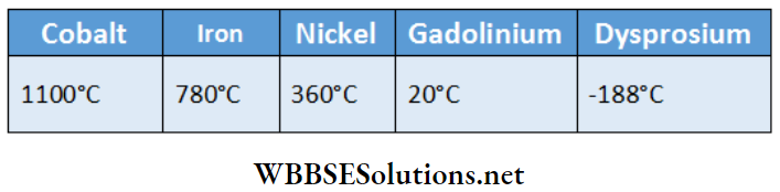
6. If a ferromagnetic material is heated gradually, at a particular temperature the material loses its ferromagnetic property completely and is converted into a paramagnetic material.
The transition temperature at which a ferromagnetic material is converted into a paramagnetic one is called the Curie point or Curie temperature for that material.
Above Curie point, magnetic susceptibility obeys Curie-Weiss law. Curie points of some materials are mentioned in Table.
7. Even if the inducing magnetic field is removed, a ferromagnetic material can retain some induced magnetism, i.e., a ferromagnetic material possesses magnetic retentivity.
It should be mentioned here that, though a ferromagnetic material can be converted into a paramagnetic one by heating above Curie temperature, ferromagnetism, and paramagnetism are two separate phenomena.
A paramagnetic material cannot be converted into a ferromagnetic material by cooling. The change is irreversible.
Magnetic screen:
A magnetic screen is an arrangement that works on the property of ferromagnetism and with this, a region can be kept free from the influence of any external magnetic field.
If a magnetic needle is kept in front of any pole of a bar magnet, the needle gets deflected. But if a plate of soft iron is placed in between them, the magnetic needle suffers no deflection.
This is because the magnetic permeability of the plate of soft iron is much greater than that of air.
Hence, the magnetic lines of force emerging from the bar magnet try to traverse the maximum distance through the plate of soft iron, and hence the lines of force cannot cross over to the other side of the plate.
Therefore, the region beyond the plate remains free from the influence of the magnetic field.
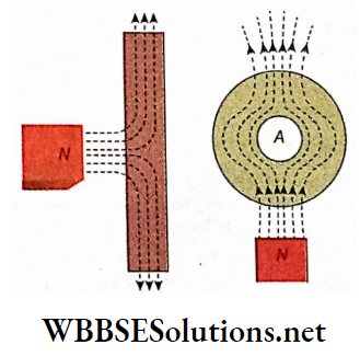
Similarly, if a soft-iron ring is placed in front of any pole of a bar magnet, most of the lines of force pass through the iron ring just avoiding the air gap inside the ring.
Since no line of force enters this region A inside the ring, it remains free from the influence of all external magnetic fields. If a magnetic needle is placed in that region, it sets itself at rest in any direction.
So, a magnetic material used to make a particular region free from the influence of any external magnetic field is called a magnetic screen.
Magnetic screens made of soft iron are used to protect delicate measuring instruments like galvanometers, ammeters, etc., from external magnetic fields. To make a costly wristwatch antimagnetic, a soft iron ring is fitted around it.
Comparison of Ferromagnetic, Paramagnetic and Diamagnetic Materials:
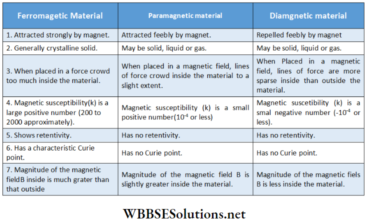
Magnetic Properties derivations For Class 12 WBCHSE
Magnetic Properties Of Materials Geomagnetism
A freely suspended magnet always sets itself at rest along the north-south direction. If disturbed, it will again come to the previous position after a few oscillations.
This phenomenon is observed anywhere on the earth. Since only a magnetic field can influence a magnet, we can infer that a magnetic field exists throughout the earth, i.e., the earth behaves as a magnet.
The following two phenomena can be mentioned in support of this concept:
1. If a soft iron rod is kept at a place on the surface of the earth facing north-south direction, after a long period (say, six months), a feeble magnetism is found to have developed in the rod.
2. If a closed conductor is moved in a magnetic field an electric current is induced in that conductor. Similarly, if a closed conductor is moved at any place on the earth’s surface, a feeble electric current is seen to be induced in that conductor.
The Earth is a huge magnet: To explain the cause of the above-mentioned phenomena, scientists concluded that the Earth behaves as a huge magnet In 1600, physicist William Gilbert suggested this theory for the first time.
Later on, Gilbert performed a simple experiment. He shaped a lodestone into a sphere and demonstrated that small magnets placed at different positions on the sphere behave exactly as they do on Earth.
Locations of the Earth’s magnetic poles: Like an ordinary magnet, the Earth’s magnet also has two poles. The north pole of Earth’s magnet is situated at Ellef Ringnes Island in Canada.
The latitude and longitude of this region are 78.3°N and 104° W. This region is at an approximate distance of 1300 km from the geographical north pole.
The south pole of the earth’s magnet is located in the sea near the sea-shore of Wilkes Land belonging to Antarctica.
The latitude and longitude of this region are 65°S and 139°E. This region is at a distance of about 2550 km from the geographical south pole.
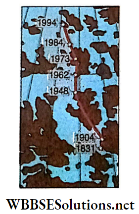
These poles are not stationary. The north pole shifts towards the northwest by 15 km every year; the shifting of the south pole is nearly the same. At present times, the magnetic axis of the earth is inclined at an angle of 11.5° with its geographical axis and the distance of the earth’s magnetic axis from the center of the earth is about 1120 km.
Nature of Earth’s magnetic poles:
The pole of a magnetic needle that points towards the north is called the north-seeking pole or simply the north pole, and the pole that points towards the south is called the south-seeking pole or simply the south pole.
The magnetic poles of Earth at the north and the south are called the magnetic north pole and magnetic south pole. Now, the north and south poles of a magnetic needle direct themselves towards the magnetic north and south poles of the earth.
It means that the north pole of the earth behaves as the south pole of an ordinary magnet and the south pole of the earth as the north pole of an ordinary magnet Sometimes the north pole of the earth’s magnet is called the blue pole and its south pole is called a red pole.
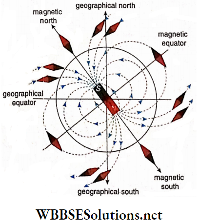
Geomagnetic Field:
The magnetic field of the earth extends up to a great height above its surface. Practically, the influence of this field is found up to a height of 105 kilometers (approx.) above the earth’s surface.
There was no clear concept about the source of the geomagnetic field for a long time. If we imagine a bar magnet kept inclined at an angle of 11.5° with the geographical axis at the center of the earth, it is possible to describe the alignment of the geomagnetic field more or less correctly. For a hypothetical bar magnet, the nature of the lines of force.
Sources of geomagnetic field: The geomagnetic field has three different sources. From these three sources, the following three magnetic fields are produced.
1. Main field: The source of this magnetic field is the outer core of Earth which is made of liquid iron. The electric current in this part produces the main field. The main field develops 97% to 99% of the geomagnetic field.
2. Crustal field: The source of this magnetic field is the earth’s crust Some parts of the earth’s crust made of hard rock become magnetized due to the presence of the main field. This magnetized part creates the crustal field. 1% to 2% of the geomagnetic field is due to this crustal field.
3. External field: The source of this magnetic field is the ionosphere present in the atmosphere of Earth. This part made up of ions, produces the external field under the influence of solar wind. 1% to 2% of the geomagnetic field is due to this external field.
Direction of the geomagnetic field: Magnetic lines of force of the geomagnetic field are naturally from the N-pole to the S-pole. But the geomagnetic N-pole is in the south and the S-pole is in the north, As a result, to show the direction of the geomagnetic field at a place, the arrow sign on each line of force should be from the south to the north direction.
Magnetic Properties Derivations For Class 12 WBCHSE Elements of Earth’s Magnetism:
To know the magnitude and direction of the geomagnetic field at any place on Earth, the quantities required are called the elements of Earth’s magnetism. There are three elements of earth’s magnetism.
These are:
- Angle of dip
- Angle of declination
- Horizontal component of geomagnetic intensity.
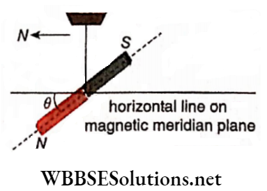
Dip or angle Of dip: The angle made by the intensity of the earth’s magnetic field with the horizontal at any place on the earth is called dip or angle of dip at that place. If a bar magnet is suspended from its center of gravity by a thread, the magnet at rest, does not remain horizontal but inclines a little.
This means that the magnetic axis sets’ itself along the direction of the intensity of the geomagnetic field at that place. The angle (θ) made by the magnetic axis with the horizontal straight line drawn on the magnetic meridian is called dip or the angle of dip at that, place.
So, if the angle of a place is known,’ We can determine the direction of the intensity of the magnetic field at that place.
Positive and negative dips: The inclination of a magnet is different at different places on Earth, i.e., the values of the dip are different at different places. If the north pole of a magnet leans downwards at a place, the value of the dip is taken as positive; but if the south pole of the magnet leans downwards, the dip at that place is taken as negative.
Positive and negative dips are denoted by the symbols N and S, respectively. For any place in the northern hemisphere of the earth, the angle of dip becomes positive, but for places in the southern hemisphere, this angle of dip is negative.
‘The angle of dip at Kolkata is 31° N’, which means that if a magnet is suspended from its center of gravity at Kolkata, the north pole of the magnet leans downwards and the magnetic axis of the magnet inclines at an angle of 31° with the horizontal plane.
At the two magnetic poles of the earth, angles of dip are 90° each, i.e., at these two places, a freely suspended magnet remains vertical. At the magnetic equator, the angle of dip is 0°, i.e., a freely suspended magnet remains horizontal at the magnetic equator.
Declination or angle of declination: The geographical poles and the magnetic poles of the earth are not located in the same places. So if a magnetic needle, capable of rotating in the horizontal plane freely, is kept at a place, we will observe that, at rest, the magnetic axis of that needle makes a definite angle with the geographical north-south horizontal line at that place.
At different places on the earth’s surface, the value of this angle is different The vertical plane passing through the magnetic axis of a freely suspended magnetic die at any place is called the magnetic meridian at that place. Again, the vertical plane at a place containing the geographical north and south poles of Earth is called the geographical meridian at that place.
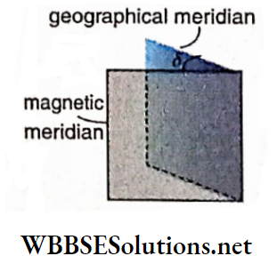
Definition: The angle between the magnetic meridian and the geographical meridian at a place is called the angle of declination at that place.
It is usually denoted by the symbol δ. If the north pole of the magnetic needle turns towards the east or the west concerning the geographical meridian, the angle of declination is called \(\delta^{\circ} E \text { or- } \delta^{\circ} W\), respectively.
For Example, the angle of declination of Delhi is 2°E means that at Delhi, the north pole of a magnetic needle capable of rotating freely on a horizontal plane moves away from the geographic meridian towards east through 2°.
Naturally, the angles of declination at different places on the earth are different. At a place, where the magnetic meridian and geographical meridian coincide, the angle of declination becomes zero.
Horizontal component of geomagnetic intensity: The direction of the geomagnetic intensity at a place does not lie on the horizontal plane usually, but it inclines at a definite angle with the horizontal plane.
This definite angle is called the angle of dip. Since magnetic intensity is a vector quantity, the geomagnetic intensity can be resolved into a horizontal component and a vertical component It should be clear that these two components lie on the magnetic meridian.
ABCD is the geographical meridian and GBCJ is the magnetic meridian. At point B, the magnitude and direction of the geomagnetic intensity I can be represented by BR. The magnitudes and directions of the vertical component V and the horizontal component H of I can be expressed by BM and BN, respectively.
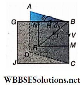
Let the angle of dip be 8 and the angle of declination be δ.
∴ V = Isinθ and H = Icosθ
or, \(\frac{V}{H}=\frac{I \sin \theta}{I \cos \theta}=\tan \theta\)
∴ V = Htanθ…(1)
Again, V² + H² = I²sin²θ + I²cos²θ = I²
∴ \(I=\sqrt{V^2+H^2}\)….(2)
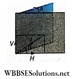
The value of the horizontal component H of geomagnetic intensity is not the same throughout the earth’s surface face. At the magnetic equator, θ = .0° and hence H = I; this is the maximum value of H. Again, at the magnetic poles, θ = 90° and hence H = 0; this is the minimum v value of H. Note that, at a place where the angle of dip is 45°, the values of horizontal and vertical components are equal.
The elements of earth’s magnetism for the northern hemisphere. In the case of the southern hemisphere, the elements.
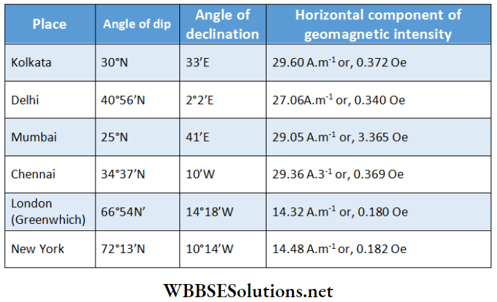
‘Horizontal component of earth’s magnetic field at Kolkata is 0.37 Oe’ means that the magnitude of the horizontal component of the geomagnetic intensity, i.e., the force acting on a unit pole along the magnetic meridian at that place is 0.37 Dyn.
In most cases, we require the horizontal component of the geomagnetic Intensity, the vertical component Is of less importance. This is because the magnetic needles we use in the laboratory, can rotate in the horizontal plane but not In the vertical plane.
As a result,’ only the horizontal component acts on the needle to create deflection in it, but the vertical component does not affect it,
Magnetic Properties derivations for Class 12 WBCHSE Values of the geomagnetic elements at some places:
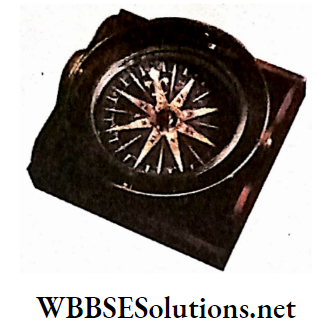
Mariner’s Compass:
Mariner’s compass, as the name suggests, is used to ascertain the direction in the sea when the sun, the pole star, or other stars are not visible.
The construction of a compass is based on the directive property of a magnet.
Working principle: Noting the position of the crown mark on the compass disc, navigators determine the direction. The crown mark on the compass disc indicates the magnetic north.
To determine the geographical north at a place, the angle of declination at the place should be collected from the magnetic maps. If the value of that declination is δ°W, it should be understood that the crown mark lies at an angle of δ°, west of the geographical north.
In this way from the position of the crown mark on the compass disc, navigators can determine directions.
Magnetic Maps: F
Values of the elements of Earth’s magnetism are different at different places on Earth. But the value of any one of the elements at different places on earth’s surface may be the same.
The places on the earth’s surface possessing the same value of a particular element are along a line. Thus different lines are drawn for different values of that element.
The geographical map of Earth containing such lines is called a magnetic map. For three different elements of Earth’s magnetism, three different magnetic maps are obtained.
The values of Earth’s magnetic elements at a particular place change gradually with time. Hence new magnetic maps should be drawn at different times. Maps of this kind are essential to navigators and also for searching minerals under the earth’s crust Three different kinds of magnetic maps.
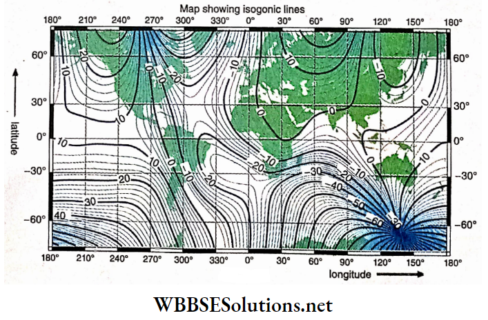
Isogonic lines:
Places on earth’s surface, having equal declination are joined by lines, called isogonic lines. The lines shown are isogonic lines drawn in 2000 AD. The lines of zero declination are called agonic lines.
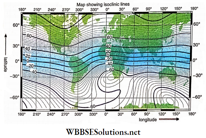
Isoclinic lines:
The lines obtained by joining the places on the earth’s surface having equal dips are called isoclinic lines. The lines shown are isoclinic lines drawn in -2000 AD. The line of zero angle of dip corresponds to the magnetic equator, and it is called an aclinic line.
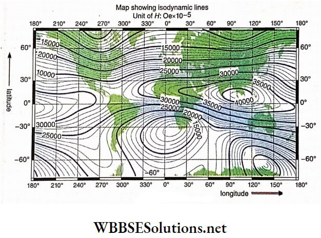
Isodynamic lines:
Places on the earth’s surface having equal horizontal components of geomagnetic field intensity are joined by lines, called isodynamic lines. The lines are isodynamic lines drawn in 2000 AD.
Magnetic Properties derivations for Class 12 WBCHSE Variations of the Elements of Geomagnetism:
The values of the elements of geomagnetism are different at different places on the earth. Again, at a particular place, the values of these elements do not remain the same always; they vary with time. This change is periodic, i.e., after a definite period, the elements return to their initial values. This kind of variation is known as periodic or regular variation.
Besides this, the elements of geomagnetism suffer another kind of variation. This kind of variation is known as a magnetic storm.
Regular variation: Regular variations are of three kinds
- Daily variation,
- Annual variation
- Secular variation.
Daily variation: The elements of geomagnetism undergo a kind of slow variation daily. At two different specific times on a day, any element of geomagnetism attains maximum and minimum values.
Annual variation: The elements of geomagnetism also undergo a kind of very slow variation. On two specific months in a year, the value of any element becomes maximum and minimum.
For Example, in London, the declination is found to have a maximum value in February and a minimum value in August every year. Variations of declination in the northern and southern hemispheres are just the opposite.
Secular variation: A kind of secular variation is observed in the elements of geomagnetism. The rate of this kind of variation is very slow, and its period is approximately 960 years. Perhaps this variation is due to the rotation of the earth’s magnetic north and south poles around its geographical south and north poles, respectively.
Magnetic storm: Sometimes sudden huge changes in the elements of geomagnetism are seen throughout a large region on the earth’s surface. This phenomenon is known as a magnetic storm. This kind of variation cannot be predicted.
However, after a while, the values of the elements return to their normal state. Magnetic storms usually occur due to earthquakes, volcanic eruptions, aurora borealis, the appearance of large sunspots, etc. During a magnetic storm, radio communication, television, telephone systems, etc. are disturbed greatly.
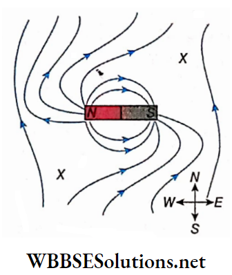
Lines of Force of a Bar Magnet in Earth’s Magnetic Field Neutral Points:
In the discussions of the magnetic lines of force of a bar magnet, the influence of the earth’s magnetic field has not been taken into account so far. The lines of force for the geomagnetic field at a place remain parallel to the magnetic meridian at that place and the direction of the lines of force is from south to north. The pattern of the lines of force near a bar magnet gets distorted under the influence of the geomagnetic field. A few cases are shown below.
N-pola pointing north: Let a bar magnet be placed along the magnetic meridian in such a manner that its 4-pole points north. In this case, the pattern of the magnetic lines of force due to the combined effect of the geomagnetic field and the magnetic field due to the bar magnet is shown.
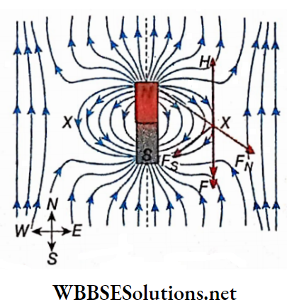
In the vicinity of the magnet, the lines of force are curved. In this region, the influence 6f the .bar magnet is more effective. The greater the distance from the magnet, the lesser its influence but the greater the influence of the geomagnetic field.
At a sufficient distance from the magnet,” its influence almost vanishes. In that region, ‘the lines of force due to geomagnetic field only. Hence, those lines of force are straight, parallel, and directed from south to north
At different points on the axis of the bar magnet, as the lines of force due to the bar magnet and geomagnetic field are; in the same direction, the value of the magnetic intensity increases.
But at different points on the perpendicular bisector of the magnetic axis, as the lines of force due to the geomagnetic field and the bar magnet are opposite in direction, the value of the magnetic intensity decreases.
On this perpendicular bisector, there are two points X and, X where the intensities due to the geomagnetic field and the magnetic- field of the magnet become equal and opposite.
As a result, these two intensities cancel each other; i.e., at these two points, the resultant magnetic intensity becomes zero. These two points are known as neutral points.
They lie at equal distances on either side of the magnet. A magnetic needle placed at any of these two natural points does not show any ‘directive property. Naturally, ho line of force passes through the neutral points.
Neutral point: A point in a magnetic field where the resultant magnetic intensity due to the superposition of two or more magnetic fields becomes zero is called a neutral point.
When the N-pole of the bar magnet points north, at the neutral point,
F = H
or, \(\frac{p_m}{\left(d^2+l^2\right)^{3 / 2}}=H\) [in CGS system]
[where, F-resultant intensity due to the bar magnet, H = horizontal component of geomagnetic intensity, pm = magnetic moment of the bar magnet, d distance, of the neutral point from the center of the bar magnet, and 2l = magnetic length of the bar magnet.]
For a tiny bar magnet, \(\frac{p_m}{d^3}=H\). Usually, if the value of d is more than ten times l, then l2 can be neglected compared to d2.
S-pola pointing north: Let a bar magnet be placed along the magnetic meridian in such a way that its S-pole points north. In this case, the pattern of the magnetic lines of force is due to the combined effect of the geomagnetic field and magnetic field due to the bar magnet.
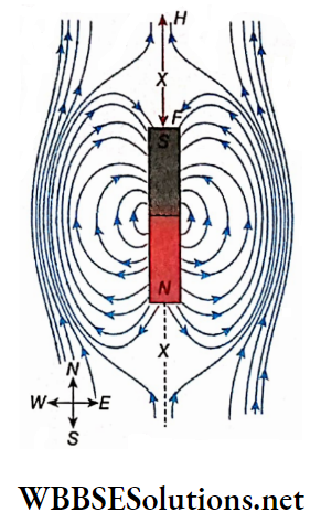
Here the neutral points (X, X) lie on the axis of the bar magnet at equal distances from its two ends.
When the S-pole of the bar magnet points north, at neutral points,
⇒ \(F=H \quad \text { or, } \frac{2 p_m d}{\left(d^2-l^2\right)^2}=H \text { [in CGS system] }\)
[where, F = intensity of the bar magnet, H = horizontal component of the geomagnetic field, pm = magnetic moment of the bar magnet, d = distance of the neutral point from the center of the magnet, and 21 = magnetic length of the bar magnet]
For a tiny bar magnet, \(\frac{2 p_m}{d^3}=H\). If the value of d is more than
10 times of l, then l2 can be neglected compared to d2.
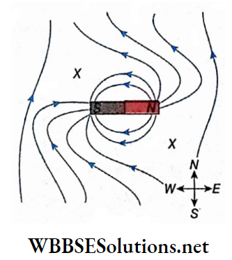
N – pole pointing east: The north pole of a bar magnet points east, the pattern of magnetic lines of force due to the combined effect of the geomagnetic field and the magnetic field of the bar magnet. The two points X, X at the northwest and southeast of the bar magnet are the neutral points. These are at equal distances from the center of the magnet.
N-pole pointing west: If the north pole of a bar magnet points west, the pattern of the magnetic lines of force is due to the combined effect of the geomagnetic field and magnetic field due to the bar magnet. The two points X, X at the northeast and southwest of the magnet are the neutral points. Their distances from the center of the magnet are equal.
Magnetic Properties Of Materials Numerical Examples
Example 1. The angle of dip at a place is 30° and the horizontal component of the earth’s magnetic field at that place is 0.39 CGS units. Determine the vertical component of the earth’s magnetic field at that place.
Solution:
Here, θ = 30° and H = 0.39 CGS units.
If the intensity of the earth’s magnetic field is I, then
⇒ \(H=I \cos \theta \quad \text { or, } I=\frac{H}{\cos \theta}\)
Vertical component,
⇒ \(V=I \sin \theta=\frac{H}{\cos \theta} \cdot \sin \theta=H \tan \theta\)
⇒ \(0.39 \times \tan 30^{\circ}=0.39 \times \frac{1}{\sqrt{3}}=0.225 \text { CGS units }\)
Example 2. At two places, the angles of dip are 30° 1V and 30° S and the intensity of the earth’s magnetic field is 0.42 Oe. Determine the horizontal and the vertical components of the earth’s magnetic field at these two places and also indicate their directions with the help of a diagram.
Solution:
At the first place, θ = 30° N, and at the second place, θ = 30°S.
The intensity of the earth’s magnetic field at both places, I = 0.42 Oe
Horizontal component,
⇒ \(H=I \cos 30^{\circ}=0.42 \times \frac{\sqrt{3}}{2}=0.364 \mathrm{Oe}\)
and vertical component,
⇒ \(V=I \sin 30^{\circ}=0.42 \times \frac{1}{2}=0.210 \mathrm{e}\)
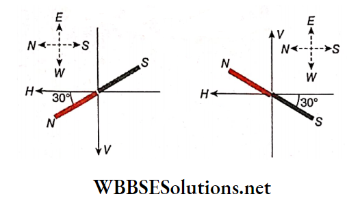
Example 3. At a place, the horizontal and vertical components of the earth’s magnetic field are 0.3 Oe and 0.2 Oe, respectively. Determine the resultant intensity and angle of dip there.
Solution:
Here, H = 0.3 Oe, V = 0.2 Oe.
If the resultant intensity is I then
⇒ \(I=\sqrt{H^2+V^2}=\sqrt{(0.3)^2+(0.2)^2}=\sqrt{0.13}=0.3605 \mathrm{Oe}\)
If the angle of dip is θ then,
⇒ \(\tan \theta=\frac{V}{H}=\frac{0.2}{0.3}=0.6667\)
∴ \(\theta=\tan ^{-1}(0.6667)=33.69^{\circ}\)
Example 4. The angle of dip and the horizontal component of the earth’s magnetic field at a place is 30° S and 0.36 Oe. Determine the magnitude and direction of the vertical component of the earth’s magnetic field at that place.
Solution:
Here, θ = 30° S. So, in equilibrium, the south pole of the magnetic needle leans downwards.
We know that, tanθ = \(\frac{V}{H}\)
∴ V = vertical component of the earth’s magnetic field,
= Htanθ
= 0.36tan30° [∵ H = 0.36 Oe]
⇒ \(0.36 \times \frac{1}{\sqrt{3}}\)
= 0.208 Oe
Since the north pole of the magnetic needle lies above the horizontal line, the direction of the vertical component (V) will be vertically upwards.
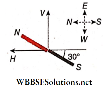
Examples of Applications of Magnetic Materials
Example 5. At a place, the angle of declination is 30°E and the angle of dip is 45°N. Determine the horizontal and vertical components of the geomagnetic intensity In the geographical meridian at that place. Given, the horizontal component of earth’s magnetic held at that place = 0.3 Oe.
Solution:
Here, 8 = 30°E, 0 = 45°A’ and H = 0.3 Oe.
If the horizontal component of the earth’s magnetic field in the geographical meridian is H’
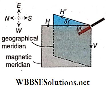
⇒ \(H^{\prime}=H \cos \delta=0.3 \cos 30^{\circ}=0.3 \times \frac{\sqrt{3}}{2}=0.2598 \mathrm{Oe}\)
The vertical component remains the same in the geographical and the magnetic meridian planes, hence
V = Htanθ
= 0.3 tan45°
= 0.3 x 1
= 0.3 Oe
Example 6. The mass of a magnetic needle is -7.5 g and its magnetic moment is 98 units. To keep the magnetic needle horizontal in the northern hemisphere, what should be the position of its fulcrum concerning its center of gravity? The vertical component of the earth’s magnetic field = 0.25 Oe.
Solution:
Let the fulcrum be kept at a distance x (towards the north pole) from the center of gravity to keep the magnetic needle horizontal.
If the length of the magnetic needle = 2l and the strength of each pole = m, magnetic moment, pm = m.21.
∴ In equilibrium,
mV.2l = W.x
or, V.pm = W.x
or, \(x=\frac{V^{:} \dot{p}_m}{W}=\frac{0.25 \times 98}{7.5 \times 980}\)
= 0.0033cm
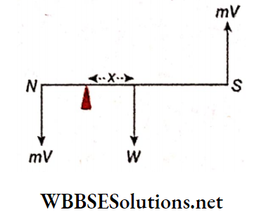
Example 7. The magnetic moment of a magnetic needle of mass 3.2 g is 980 CGS units. From which point should the needle be hung so that it will remain horizontal in the magnetic meridian? The horizontal component of the earth’s magnetic field at that place is 0.32 Oe and the angle of dip = 45°N. [g = 980 cm.s-2]
Solution:
Let the magnetic needle be hung from a point at a distance x from its center of gravity (towards the north N pole)
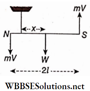
In equilibrium,
mV x 2l = W.x
or, V.pm = W.x [∵ Pm = m.2l]
or, \(x=\frac{V \cdot p_m}{W}=\frac{H \tan \theta \cdot p_m}{W}\) [∵ V = Htanθ]
⇒ \(=\frac{0.32 \times \tan 45^{\circ} \times 980}{3.2 \times 980}\)
= 0.1cm
Example 8. The angle of dip at a place = θ; if the angle of dip in a vertical plane making angle δ with the magnetic meridian be θ’, show that tanθ’: tanθ = Secδ: 1
Solution:
If the true dip angle in the magnetic meridian is θ, the vertical and horizontal components of earth’s magnetic field are V and H, respectively then,
⇒ \(\tan \theta=\frac{\dot{V}}{H}\)
In a vertical plane inclined at an angle δ with the magnetic meridian, the horizontal component of intensity,
H’ = Hcosδ, apparent dip at that plane = θ’ and vertical component = V.
∴ \(\tan \theta^{\prime}=\frac{V}{H^{\prime}}=\frac{V}{H \cos \delta}=\tan \theta \cdot \sec \delta\)
or, \(\frac{\tan \theta^{\prime}}{\tan \theta}=\sec \delta\)
∴ \(\tan \theta^{\prime}: \tan \theta=\sec \delta: 1\)
Example 9. At a place, the apparent geomagnetic dip in a vertical plane is 40°, and in another plane, perpendicular to it is 30°. What is the real dip at the place? Similar problem: If θ1 is the angle of dip of the magnetic axis of a magnetic needle with horizontal at any vertical plane and θ2 is that in another vertical plane at right angles to the former, prove that the real angle of dip, θ is given by \(\cot ^2 \theta=\cot ^2 \theta_1+\cot ^2 \theta_2\).
Solution:
If the horizontal and vertical components of the earth’s magnetic field are H and V, respectively and the true dip angle at that place is θ then,
⇒ \(\tan \theta=\frac{V}{H}\)…..(1)
M is the magnetic meridian and X, and Y are two vertical planes inclined at a right angle to each other.
The angle between the planes X and M is δ. If the apparent dip in the plane X is θ1 then,
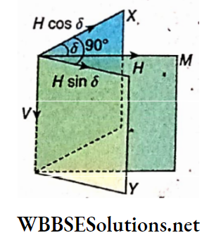
⇒ \(\tan \theta_1=\frac{V}{H \cos \delta}\)….(2)
If the apparent dip in plane Y is θ2 then,
⇒ \(\tan \theta_2=\frac{V}{H \sin \delta}\)…..(3)
From equations (2) and (3) we get,
⇒ \(\cot ^2 \theta_1+\cot ^2 \theta_2=\frac{H^2}{V^2}\left(\cos ^2 \delta+\sin ^2 \delta\right)=\frac{H^2}{V^2}\)
= cot²θ [from equation (1)]
Here, θ1 = 40° and θ2 = 30°.
∴ \(\cot ^2 \theta=\cot ^2 40^{\circ}+\cot ^2 30^{\circ}\)
or, \(\cot \theta=\sqrt{1.42+3}=\sqrt{4.42}=2.1\)
or, θ = cot-1(2.1)
= 25.46°
Example 10. A bar magnet of length 6 cm is kept vertically with its north pole on the ground. If the distance of the neutral point on the ground is 8 cm from the north pole, what will be the magnetic moment of that magnet? [If = 0.36 CGS units]
Solution:
Let O be the neutral point
Here, NS = 6 cm, NO = 8 cm
So, \(S O=\sqrt{6^2+8^2}=10 \mathrm{~cm}\)
If the pole strength of the magnet NS is qm, magnetic intensity at the point O due to the north pole,
⇒ \(H_1=\frac{q_m}{O N^2} \text {, in the direction of } O A \text { [in CGS] }\)
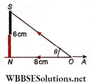
Again, due to the south pole magnetic intensity at the point O,
⇒ \(H_2=\frac{q_m}{O S^2} \text {, in the direction of } O S\)
∴ Component of H2 in the direction ON,
⇒ \(H_2 \cos \theta=\frac{q_m}{O S^2} \cdot \frac{O N}{O S}\)
So, the horizontal magnetic intensity at the point O due to the entire magnet,
⇒ \(H_1-H_2 \cos \theta=\frac{q_m}{O N^2}-\frac{q_m}{O S^2}: \frac{O N}{O S}=q_m\left(\frac{1}{8^2}-\frac{1}{10^2} \times \frac{8}{10}\right)\)
= qm x 0.007625 Oe
Since O is the neutral point, the magnetic intensity at that point due to the magnet will be equal but opposite to the horizontal component H of Earth’s magnetic field.
∴ \(q_m \times 0.007625=0.36 \quad \text { or, } q_m=\frac{0.36}{0.007625} \mathrm{emu} \cdot \mathrm{cm}\)
∴ Magnetic moment of the magnet
⇒ \(q_m \cdot N S=\frac{0.36}{0.007625} \times 6=283.3 \mathrm{emu} \cdot \mathrm{cm}^2\)
Example 11. A bar magnet of length 8 cm is placed on a horizontal plane in the magnetic meridian with its north pole pointing north. If the magnetic moment of the magnet is 90 CGS units and the horizontal, component of the earth’s magnetic field is 0.35 Oe, determine the positions of the neutral points.
Solution:
Let each of the two neutral points be at a distance d from the center of the magnet along its perpendicular bisector. If the magnetic moment of the magnet is pm and its magnetic length is 2l, the magnetic intensity at the neutral points due to the magnet (in the CGS system) is,
⇒ \(H_m=\frac{p_m}{\left(d^2+l^2\right)^{3 / 2}}\)
At the neutral points, the horizontal component H of the earth’s magnetic field will be equal and opposite.
∴ \(H=H_m=\frac{p_m}{\left(d^2+l^2\right)^{3 / 2}} \quad \text { or, }\left(d^2+l^2\right)^{3 / 2}=\frac{p_m}{H}\)
or, \(d^2+l^2=\left(\frac{p_m}{H}\right)^{2 / 3} \quad\)
or, \(d=\sqrt{\left(\frac{p_m}{H}\right)^{2 / 3}-l^2}\)
Here, pm = 90 CGS units, H = 0.35 Oe, 2l = 8 cm i.e.,
I = 4 cm.
∴ \(d=\sqrt{\left(\frac{90}{0.35}\right)^{2 / 3}-4^2}=4.94 \mathrm{~cm}\)
Example 12. At a place, the vertical component of the earth’s magnetic field is V3 times its horizontal component. What will be the angle of drop at that place?
Solution:
If the intensity of the earth’s magnetic field is I and the angle of dip is θ, then the horizontal component of the earth’s magnetic field, H = Icosθ, and a vertical component, V = Isinθ
According to the problem,
⇒ \(V=\sqrt{3} H \quad\)
or, \(\frac{V}{H}=\sqrt{3} \quad\)
or,\(\frac{I \sin \theta}{I \cos \theta}=\sqrt{3}\)
or, \(\tan \theta=\sqrt{3}=\tan 60^{\circ}\)
∴ θ = 60°
Magnetic Properties Derivations For Class 12 WBCHSE
Magnetic Properties Of Materials Very Short Questions and Answers
Question 1. The magnetic moment of a small bar magnet is 1 A.m2. What will be the magnitude of the magnetic field at a point 1 m away from the center of the magnet along its length?
Answer: 2 x 10⁻⁷T
Question 2. If the magnetic moment of a bar magnet of length 5 cm is 1 A.m2, what is the strength of each pole?
Answer: 20 A.m
Question 3. Pole-strengths of two magnetic poles are 1 A.m and 2 A.m. If they are kept 1 m apart in the air, then what is the magnitude of the force acting between them?
Answer: 2 x 10⁻⁷N
Question 4. A short bar magnet, placed with its axis at an angle 6 with a uniform external magnetic field B, experiences a torque r. What is the moment of the magnet?
Answer: \(\frac{\tau}{B \sin \theta}\)
Question 5. What is the unit of magnetic susceptibility?
Answer: No unit
Question 6. What is the unit of intensity of magnetization \(/vec{M}\)?
Answer: A.m-1
Question 7. If the relative magnetic permeability of a material is 1,00004, what will be its magnetic susceptibility?
Answer: 0.00004
Question 8. If the magnetic intensity at a point in a material is 100 A.m-1 and the magnetic susceptibility is 1000, what will be the value of the magnetic field at that point?
Answer: 4π x 10-2T
Question 9. If the magnetic susceptibility of a material is -0.0002, what is its relative magnetic permeability?
Answer: 0.99998
Question 10. The area of the hysteresis loop of a magnetic material A is larger than that of another magnetic material B. Which of the two materials is better suited for use as the core of an electromagnet?
Answer: Material B
Question 11. The relative permeability of iron is 5500. What is its magnetic susceptibility?
Answer: 5499
Question 12. The Curie temperature of nickel is 360°C. In which group of magnetic materials will you place nickel at 500°C?
Answer: Paramagnetic
Question 13. Name a non-magnetic alloy of iron.
Answer: Stainless Steel
Question 14. Name a material that is used as the core of an electromagnet.
Answer: Soft Iron
Question 15. For which type of material the magnetic susceptibility is negative?
Answer: Diamagnetic
Question 16. For which type of material, the magnetic susceptibility is independent of temperature?
Answer: Diamagnetic
Question 17. How does the magnetic susceptibility per unit mass (\(\chi\)) of a paramagnetic gas depend on absolute temperature T?
Answer: \(\chi \propto \frac{1}{T}\)
Question 18. If the intensity of the geomagnetic field at a place is 60 A.m-1 and the horizontal component of that intensity is 30 A.m-1, determine the angle of dip.
Answer: 60°
Question 19. Where on the surface of the earth, the value of the angle of dip is zero?
Answer: Geomagnetic equator
Question 20. Where on the earth’s surface, the value of the angle of dip is 90°?
Answer: Geomagnetic poles
Question 21. The vertical component of the earth’s magnetic field at a place is √3 times the horizontal component. What is the angle of dip at this place?
Answer: 60°
Question 22. The horizontal component of the earth’s magnetic field at a place is V3 times the vertical component. What is the angle of dip at this place?
Answer: 30°
Magnetic Properties Of Materials Fill in The Blanks
1. The ratio of the magnetic field \(\vec{B}\) at a point in a material to the magnetic permeability of that material is called the intensity of the magnetic field \(\vec{H}\) at that point.
2. The magnetic moment per unit volume of a material due to unit magnetic intensity is called the magnetic susceptibility of that material.
3. The horizontal component of the earth’s magnetic field exists in all regions except at the geomagnetic poles
Magnetic Properties Of Materials Assertion Reason Type
Direction: These questions have Statement 1 and Statement 2. Of the four choices given below, choose the one that best describes the two statements.
- Statement 1 is true, Statement 2 is true; Statement 2 is a correct explanation for Statement 1.
- Statement 1 is true, Statement 2 is true; Statement 2 is not a correct explanation for Statement 1.
- Statement 1 is true, Statement 2 is false.
- Statement 1 is false, and Statement 2 is true.
Question 1.
Statement 1: The magnetic moment of an electron rotating in an atom is proportional to its angular momentum.
Statement 2: The electrons in an atom can rotate only in those orbits for which the angular momentum of the electron is an integral multiple of \(\frac{h}{2 \pi}\)(h= Planck’s constant).
Answer: 2. Statement 1 is true, Statement 2 is true; Statement 2 is not a correct explanation for Statement 1.
Question 2.
Statement 1: Soft iron is preferred for making electromagnets.
Statement 2: Both the permeability and retentivity of soft iron are high.
Answer: 3. Statement 1 is true, Statement 2 is false.
Question 3.
Statement 1: The magnetic lines of force inside a piece of copper placed in a uniform magnetic field move away from each other.
Statement 2: The permeability of diamagnetic material is less than one.
Answer: 1. Statement 1 is true, Statement 2 is true; Statement 2 is a correct explanation for Statement 1.
Question 4.
Statement 1: The intensity of Earth’s magnetic field may be different even if the horizontal component of Earth’s magnetic field is the same at two different places.
Statement 2: The horizontal component of the earth’s magnetic field is Isinθ where I am the intensity of the earth’s magnetic field and θ is the angle of dip at a place.
Answer: 3. Statement 1 is true, Statement 2 is false.
Question 5.
Statement 1: The B-H curve of a ferromagnetic material is not linear which means that these materials do not obey \(\vec{B}=\mu \vec{H}\) rule.
Statement 2: The permeability of a ferromagnetic material is not constant, it can even have a negative value
Answer: 4. Statement 1 is false, Statement 2 is true.
Magnetic Properties Of Materials Conclusion
- A current loop behaves as a magnetic dipole.
- The product of the effective area of a current-carrying loop and the current flowing through that loop is called the magnetic moment of the loop.
- The behavior of a current-carrying circular coil is similar to that of a permanent magnet.
- The behavior of a current-carrying solenoid is similar to that of a permanent bar magnet.
- The ratio of the magnetic moment to the effective length of a magnet is the pole strength of that magnet. The strengths of the two poles of a magnet are equal but opposite.
- Inside a magnetic material, the lines of force produced as a result of the superposition of the lines of force due to ‘the induced magnetic field and the lines of magnetization are called magnetic lines of induction.
- If air or vacuum is replaced by any other material the fractional change in the magnetic field in that material is called the relative magnetic permeability (r) of that material.
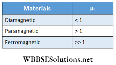
- Tire intensity of magnetization (M) at a point, is defined as the magnetic moment of a unit volume surrounding the point.
- The amount of induced magnetic moment per unit volume of a material due to unit magnetic intensity is called the magnetic susceptibility of that material.
- The ratio of magnetic susceptibility and its density is called the mass (magnetic) susceptibility of the material.
- The property by which a magnetic material retains some magnetism even after the withdrawal of the external magnetic field is called the magnetic retentivity of the material.
- The property by which a magnetic material can retain induced magnetism even if it is handled roughly is called the coercivity of the material.
- Magnetic susceptibility per unit mass of a paramagnetic material, \(\dot{\chi}=\frac{k}{\rho} \cdot(\rho=\text { density })\) varies inversely with the absolute temperature. So, \(\chi=\frac{C}{T}\) (for a particular-material C is constant). This is known as Curie law.
- Diamagnetism is the most fundamental magnetic property of all materials.
- The critical temperature at which a ferromagnetic material is converted into a paramagnetic material is called the Curie point dr Curie temperature of that material.
- To make a particular place free from any external magnetic influence, a magnetic material having high magnetic permeability is used as a magnetic screen.
- The earth behaves as a huge magnet.
- Earth’s magnetic north pole is situated near its geographic south pole and the magnetic south pole is situated near its geographic north pole,
The elements of earthly magnetism are:
- The angle of dip,
- Angle of declination
- Horizontal component of the earth’s magnetic intensity.
The angle made by the tire intensity of the earth’s magnetic field with the horizontal at a place on the earth is called, the angle of dip at that place.
- The angle between the magnetic meridian and geographical meridian at a place is called the angle of declination at that place.
- Due to the superposition of two or more magnetic fields at a point, if the resultant, magnetic field becomes zero, then that point is called a neutral point.
- The magnetic moment of a current loop (it is a magnetic dipole), \(\vec{p}_m=N I \vec{A}\)
- where, I = current through the loop, \(\vec{A}\) = vector indicating the area of the loop and N = number of turns.
- The torque acting on a bar magnet in a magnetic field,
⇒ \(\vec{\tau}=\vec{p}_m \times \vec{B}\)
- The magnetic moment of a bar magnet of effective length 21 is,
⇒ \(\vec{p}_m=2 q_m \vec{l} \text { [where } q_m=\text { pole-strength] }\)
- The mutual force between two magnetic poles of pole strengths strengths \(q_m \text { and } q_m^{\prime}\) is,
⇒ \(F=\frac{\mu_0}{4 \pi} \cdot \frac{q_m \cdot q_m^{\prime}}{r^2}\)
- This is known as Coulomb’s law of magnetism.
Magnitudes of the magnetic field at different points due to a bar magnet:
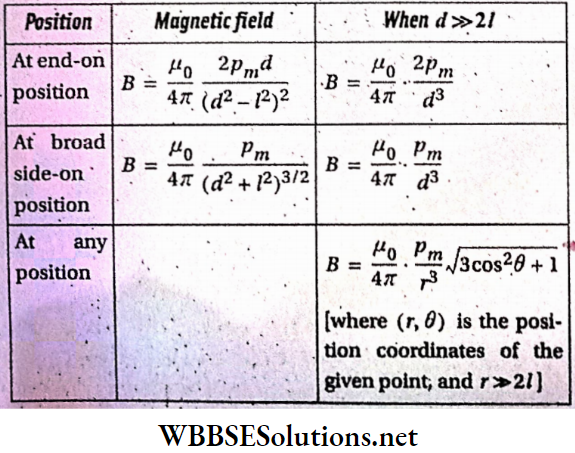
Here, d = distance of the point from the mid-point of the tire magnet, 2l = effective length of the magnet, and pm = magnetic content of the bar magnet.
The magnetic moment of a revolving charged particle (q),
⇒ \(p_m=\frac{q v r}{2}=\frac{q}{2 m} L\)
[where, r = radius of tire circle, v = speed of the particle, m = mass of the particle, L = angular momentum]
A few relations:
- \(\vec{B}_0=\mu_0 \vec{H}\)
- \(\vec{B}=\mu_0(\vec{H}+\vec{M})\)
- \(\vec{M}=k \vec{H}\)
- \(\mu_r=\frac{\mu}{\mu_0}=1+k\)
- \(\chi=\frac{k}{\rho}\)
- \(k=\mu_r-1\)
[where, B0 = magnetic field in air (or vacuum),
- B = magnetic field in airy medium,
- H = magnetic intensity in air (or vacuum),
- M = intensity of magnetization,
- μ0 = magnetic permeability of air (or vacuum),
- μ = permeability of a medium,
- μr = relative permeability of a medium,
- k = magnetic susceptibility,
- ρ = density of the medium,
- \(\chi\) = mass (magnetic) susceptibility]
If the angle of dip at a place is θ and the magnitude of tire Intensity of earth’s magnetic field is I, then the vertical component of earth’s magnetic field, V = Isinθ, and Its horizontal component H = Icosθ.
In this case, \(I=\sqrt{V^2+H^2}\)
Some physical quantities related to the magnetic property of material:
- The magnetic moment for a straight current-carrying wire is zero.
- The magnetic moment for a toroid is zero.
- A magnetized wire having length L and magnetic moment M is bent.
- Now the magnetic moment becomes \(M^{\prime}=\frac{M}{\sqrt{2}}\)
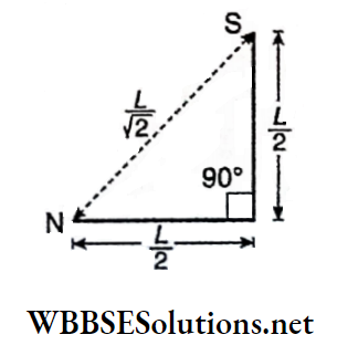
- A magnetized wire having length L and magnetic moment M is bent.
- Now the magnetic moment becomes \({M}^{\prime}=\frac{M}{2}\)
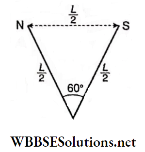
- If the magnetic latitude of a place is λ and the angle of dip is θ, then tanθ = 2tanλ.
Unit 3 Magnetic Effect Of Current And Magnetism Chapter 2 Magnetic Properties Of Materialsm Match The Columns
Question 1. Some quantities are given in column A and corresponding units are in column B.
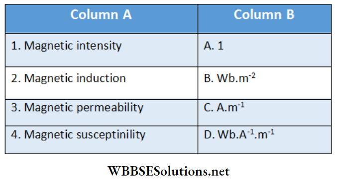
Answer: 1-C, 2-B, 3-D, 4-A
Question 2. The magnetic moment of a magnetized steel wire is p. It is bent to form different shapes, given in column A. The magnetic moments are given in column B.
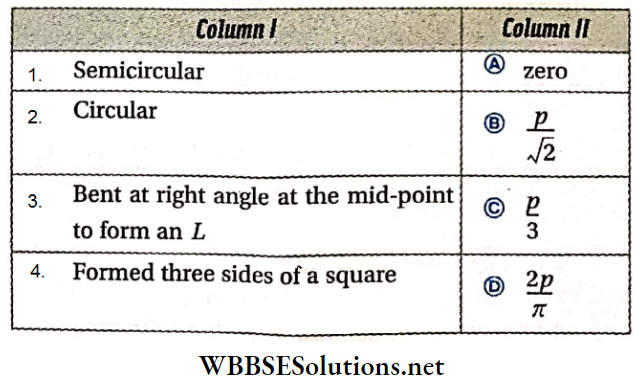
Answer: 1-D, 2-A, 3-B, 4-C