
WBCHSE Class 12 Physics Interference Notes
Light Wave And Interference Of Light Introduction
Light propagates through the vacuum or any medium in the form of waves l light wave is a transverse electromagnetic wave. Optical phenomena observed in daily life, as produced by slits or orifices, obstacles, reflecting planes, and refracting planes, have sizes many times more than the wavelength of light.
For example, the wavelength of visible light ranges from 4 × 10⁻⁵ cm but even a very small slit in the path of light generally lias a diameter not less than I mm ie, 0.1 hence, the diameter of the orifice (slit) Is 1000 times more than the wavelength of visible light. The wavelength of light is taken as zero. with respect to large orifices, slits, obstacles, reflecting surfaces or refracting surfaces, i.e., light is not considered as waves
However In cases, when the size of an orifice or obstacle, in the path of light is too small and is comparable to the wavelength of light, the wavelength of visible light can no more be taken as zero, light has to be considered waves
Read and Learn More Class 12 Physics Notes
Optics: This branch of physics deals with the properties of light
Optics is divided into two parts
- Geometrical optics and
- Physical optics.
Geometrical optics: In this branch of optics, it is assumed that the wavelength of light is negligible in comparison with the sizes of instruments used in experiments (like an orifice ot an obstacle).
Physical optics: it is assumed that the sizes of Instruments used In the experiment (litre size of an orifice ot an obstacle) are i comparable with the wavelength of light
Light Wave And Interference Of Light Wavefront
Concept of wavefront
When a Stone is chopped in a reservoir, waves are set up on its still-wet surface. I tear the centre of disturbance, i.e., where the stone is dropped, waves spread out in all directions at constant velocity. Water particles ‘ however, do not spread out horizontally with the wave.
Instead, they vibrate vertically let us that at .in instant of time the displacement of a water p.irtirle. at some distance from the centre of the disturbance. Is m.minimum At the it moment, displacements of all water particles situated on the circumference of the circle of radius same as the distance of the point in reference, are maximum.
This implies that water particles on the circumference of all circles- concentric with the circle described above, should all circle- concentric with the circle described above, should be medium in the form of circles Hence. where spreading of a wave in a dimensional medium.
If a sphere is imagined with the outer of disturb nice a; its centre, all points lying on the surface of this inference sphere, ate In the same phase. In this case spherical wavefront is obtained. If the radius of the spherical spherical wavefront is obtained. If the radius of the spherical wavefront is large enough, a small part of the wavefront can be taken as a plane wavefront
Definition: As a wave generated from a source spreads in all diet nuns through the vacuum or a medium, the locus (line or surface) points it the path of the wave which is in equal phase at any moment Is called a wavefront
WBCHSE class 12 physics interference notes Different types of wavefronts
1. Spherical wavefront:
The waveforms formed during the propagation of light coming hum a point source are considered spherical in shape the locus of the points in the same phase is spherical I In, which is known as a spherical wavefront
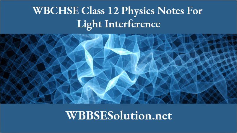
2. Cylindrical wavefront:
The wavefront produced during the propagation of light coming from a line source (for example, a single slit) is considered cylindrical in shape
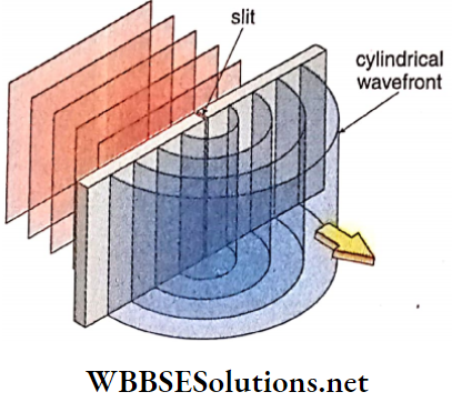
3. Plane wavefront: The rays coming from infinity are parallel and the wavefront thus associated can be considered a plane wavefront
WBBSE Class 12 Light Interference Notes
Properties of wavefronts
- A perpendicular drawn at any point on a wavefront shows the direction of velocity of the wave at that point
- The velocity of a wave actually denotes the velocity of the wavefront. If v is the wave velocity, the velocity of each wavefront the perpendicular distance between two consecutive wavefronts in the same phase is called the wavelength of that wave.
- The phase difference between any two points located on the 1 same wavefront is zero
Ray: Perpendicular drawn to the wavefront is called Energy of a wave is transmitted from one part to another in a vacuum or in a medium along these rays. Direction of rays by yellow arrowhead.
Light-Wave And Interference Of Light Huygens’ Principle Of Wave Propagation
Dutch scientist Christian Huygens introduced a geometrical method suggesting the propagation of wavefront which is very useful in interpreting reflection, refraction, interference, diffraction etc,, of waves.From the position and shape at any subsequent time Huygens principle.
Huygens’ principle
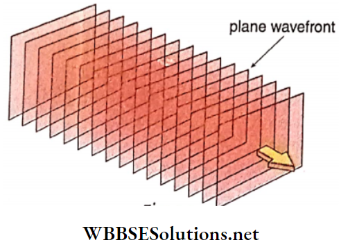
Each point on a wavefront acts as a new source called a secondary source. From these secondary sources, secondary waves or wavelets generate and propagate in all directions at the same speed of the wave. The new wavefront at a later stage is simply the common envelope or tangential plane to these wavelets
Let S be a point source of light from which waves spread in all directions. At some instant of time, AB is a spherical wavefront
According to Huygens’ principle, points P1, P2, and P3 wavefront AB act as new sources, and wavelets from these sources spread out at the same speed. Small spheres each of radius ct (c = velocity of light) with centres P1, P2, P3 respectively are imagined.
Clearly, wavelets produced by the secondary sources reach P1, P2, P3 surfaces of these imaginary spheres after a time interval. Following Huygens’ Principle, the common tangential plane AJBJ, to the front surface of small spheres should be the new wavefront In the forward direction, after a time t. In this context, it is pointed out that A1B1 is also a spherical surface with a centre at S.
Wavefronts, close to a source of light are spherical. But when a wavefront is far enough from the source of light, the Wavefront is taken to be a plane wavefront
From Huygens’ method of tracing wavefronts, like wavefront, A1B1 another wavefront A2B2 is also obtained behind AB, which can be called back wavefront. But in Huygens’ opinion, there is no existence of such a back wavefront. Later this opinion was supported theoretically and also experimentally.
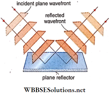
Verification of the Laws of Reflection
Using Huygens’ principle, laws of reflection of light can be proved. Reflection of a plane wavefront from a plane reflecting surface
WBCHSE class 12 physics interference notes Short Notes on Young’s Double Slit Experiment
Let AC, part of a plane wavefront, perpendicular to the plane of paper, be incident on the surface of a plane reflector XY. Note that the plane wavefront and the plane of paper intersect each other along line AC. The plane of the paper and the plane of the reflector are also perpendicular to each other. According to Huygens! each point on wavefront AC acts as a source of secondary wavelet.
Let at time t = 0, one end of the wavefront touches the reflecting surface at A. At the same moment, wavelets form from each point on the wavefront AC. These wavelets gradually reach the reflector. After a time t say, wavelet from C reaches point F of the reflector. In accordance with Huygens’ principle, all points from A to F on the reflecting plane in turn generate wavelets. Hence by the time.
The wavelet from C reaches F, wavelet generated at A reaches D in the same medium. Centring point A, an arc of radius CF is drawn. Assuming c to be the speed of light in the medium under consideration, we have CF = ct. Tangent FD is drawn on the arc. FD is the reflected wavefront after time t.
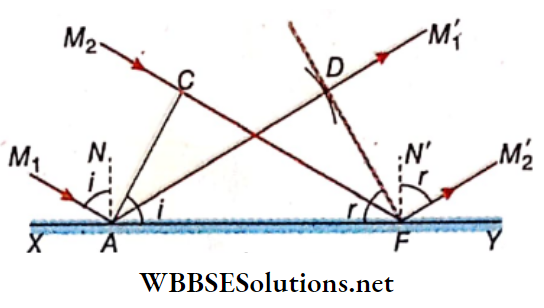
The perpendiculars M1A and M2F drawn on the incident wavefront AC are the incident rays and the perpendiculars AM’1[ and FM’2 drawn on the reflected wavefront DF are the corresponding reflected rays. NA and N’F are the normals drawn at the points of incidence on the reflector.
.-. ∠M1AN = Angle of incidence
And ∠M’2FN’ = Angle of reflection (r)
According to
∠CAF = 90°- ∠NAC= ∠M1AC-∠NAC
= ∠M1AN =i
And ∠AFD = 90°-∠N’FD= ∠M2FD-∠N’FD
= ∠M’2FN’ = r
Now from ΔACF and ΔAFD, ∠AGF = ∠ADF = 90°,
CF = AD = ct and AF is the common side.
Hence the triangles are congruent.
∠CAF = ∠AFD
∴ Angle of incidence (i) = Angle of reflection (r)
Thus one of the laws of reflection is proved.
AC, FD and AF are the lines of intersection of the incident wavefront, reflected wavefront and plane of the reflector with the plane of paper respectively, which means AC, FD and AF lie on the plane of paper. Hence the perpendiculars to these lines, that is, incident ray (M1A or M2F), reflected ray (AM1′or FM’2) and the perpendicular to the reflector (AN or FN’) at the point of incidence lie on the same plane. Thus, the other law of reflection is also proved.
∴ sini = sin r -∠CAF = \(\frac{C F}{A F}\)
And in r = sin ∠AFD = \(\frac{A D}{A F}\)
Verification of the Laws of Refraction
Laws of refraction can also be proved using Huygens’ theory of wave propagation. Refraction of a plane wavefront in a plane refracting surface is shown in
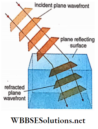
Let XY be a plane refracting surface which is the surface of separation of medium 1 and medium 2 . The speed of light in medium 1 is cx and in medium 2 is c2. Refractive indices of media 1 and 2 are μ1 and μ2 respectively.
There fore μ1 = \(\frac{c}{c_1}\) and μ2 = \(=\frac{c}{c_2}\) where c is speed of light in vacuum
The refractive index of the medium 2 with respect to that of medium
μ2 = \(\frac{\mu_2}{\mu_1}=\frac{c / c_2}{c / c_1}=\frac{c_1}{c_2}\) ………………. (1)
Assume that, part of a plane wavefront normal to the plane of paper is incident on the surface of separation of two refractive media. The wavefront and the plane of paper intersect each other along the line AC. The plane of refraction XY is also at right angles to the plane of the paper.
According to Huygens’ principle, all the points on the wavefront AC act as sources of secondary wavelets. Suppose, at t = 0, one end of the wavefront touches the plane of the refracting medium at A.
At the same moment, wavelets form from each point on the die wavefront AC. These wavelets gradually reach the plane of the refracting surface. After a time t, say, the other end C of the wavefront touches F on the surface of separation.
Following Huygens’ principle, all points from A to F on the plane of separation will in turn generate wavelets. Hence, by the time the wavelet from C reaches F, wavelets are generated at A toward medium 2.
Centring point A, nt FD is drawn to the arc from point A to F on the time the wavelet from C reaches F, wavelets generated at A advance toward medium 2. Centring point A, an are of radius C2 t is drawn. Tangent FD is drawn to the arc from point F. FD is the refracted wavefront after time t.
Naturally , CF = c1t …………. (2)
And = AD = c2 t …………. (3)
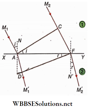
The perpendiculars M1A and M2F wavefront AC are the incident rays and the perpendiculars AM1 and FM2 drawn on the refracted wavefront DF are the corresponding refracted rays. NA and NfF are the normals drawn at the points of evidence on the surface of separation
∠M1AN = angle of incidence (i)
and ∠M2FN’ = angle of refraction (r)
According to
∠CAF = 90°- ∠NAC= ∠M1AC-∠NAC
= ∠M1AN = i And ∠AFD = 90°-∠N’FD= ∠M’2FD- ∠N’FD
= ∠M2‘FN’ = r
∴ sini = sin ∠CAF = \(\frac{A D}{A F}\)
∴ \(\frac{\sin i}{\sin r}=\frac{\frac{C F}{A F}}{\frac{A D}{A F}}\)
⇒ \(\frac{C F}{A D}=\frac{c_1 t}{c_2 t}=\frac{c_1}{c_2}\)
Or, \(1 \mu_2=\frac{\mu_2}{\mu_1}\)
Hence Snell’s law of refraction is proved.
Practice Problems on Constructive and Destructive Interference
AC, FD and AF are the lines of intersection of the incident. wavefront, refracted wavefront, and the plane of refraction with ” the plane of paper respectively which means AC, FD, and AF lie on the plane of the paper.
Hence the perpendiculars on them, that is, incident ray (M1A or M2F), refracted ray (AM1‘ or FM1′) and perpendicular to the refracting surface (AN or FN’) I lie on the same plane. Thus the other law of refraction is also proved.
Relating to the above discussion live has been drawn for the refraction from a rarer to a denser medium. The entire proof can be done for the refraction from a denser to a rarer medium as well in the same manner.
The velocity of light changes while passing from one medium to another keeping its frequency unchanged.
From equation (1) we get
⇒ \(_1 \mu_2=\frac{c_1}{c_2}=\frac{n \lambda_1}{n \lambda_2}=\frac{\lambda_1}{\lambda_2}\) …………………….. (4)
∴ c = nλ; n – frequency of light
λ1 and λ2 are the wavelengths of light in media (1) and (2) respectively. It means, the wavelength of light changes due to refraction.
Light interference class 12 notes
LightWave And Interference Of Light Huygens’ Principle Of Wave Propagation Numerical Examples
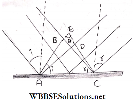
Example 1. A plane wavefront, after being Incident on a plane reflector at an angle of Incidence, reflects from It. Show that the Incident wavefront and the reflected wavefront are Inclined at an angle (180° -2i) with each other.
Solution:
AB and CD are the incident and reflected wavefronts respectively. On extending the wavefronts, they meet at E and the angle between them is 0. From ∠BAC =l and ∠DCA = r.
From ΔACE, 6 + 1+r = 180°
Or, θ = 180- (i+r) Or, θ= 180 – 2i
∴ i = r
Example 2. The wavelength of a light ray in vacuum is 5896A What will be Its velocity and wavelength when It passes through glass? Given, the refractive index of glass = 1.5 and the velocity of light In vacuum = 3 × 10⁸ m. s-1
Solution:
Here, X = 5896A°, c = 3 × 10⁸ m .s-1 μg = 1.5
We know , \(\mu_g=\frac{c}{c_g}\)
Or, \(c_g=\frac{c}{\mu_g}\)
⇒ \(\frac{3 \times 10^8}{1.5}\)
= 2 × 10⁸ m. s-1
Again, nλ =c (in vacuum) nλg = cg (in glass)
⇒ \(\frac{n \lambda_g}{n \lambda}=\frac{c_g}{c}\)
= \(\lambda^c \frac{c_g}{c}=\frac{\lambda}{\mu_g}\)
= \(\frac{5896}{1.5}\)
= 3931 A°
Conceptual Questions on Wave Optics and Interference
Example 3. Refractive indices of glass with respect to water and air were 1.13 and 1.51 respectively. If the velocity of light In air is 3 × 10⁸ m. s-1 what will be The velocity in water
Solution:
We know, \({ }_a \mu_g=\frac{c_a}{c_g}\)
∴ \(1.51=\frac{3 \times 10^8}{c_g}\)
cg = Velocity of light in the glass
Or, \(c_g=\frac{3 \times 10^8}{1.51}\)
= 2 × 10⁸ m. s-1
Again , \({ }_{w^{\prime}}{ }_g=\frac{c_w}{c_g}\) = velocity of light in water
Or, 1.13 = \(\frac{c_w}{2 \times 10^8}\)
Or, cw = 2.26 × 10⁸ m. s-1
| Class 11 Physics | Class 12 Maths | Class 11 Chemistry |
| NEET Foundation | Class 12 Physics | NEET Physics |
Light interference class 12 notes
Light Wave And Interference Of Light Principle Of Superposition Of Waves
Simultaneous propagation of a number of waves through the same space In a medium is called superposition During superposition, while one wave superposes on another, individual properties remain unaltered
Let us consider the situation where at any point in a medium a number of waves are incident at the same time. The displacement of the point would have been different if the waves passed through it individually. But as all the waves are incident at the same time, the point undergoes a resultant displacement (since displacement is a vector quantity). Clearly, resultant displacement is the vector sum of the displacements produced by each wave. This is the principle of superposition of waves. The principle can be expressed as follows
At any instant, the resultant displacement of appointing a medium due to the influence of a number of waves is equal to the vector sum of displacements produced by each individual wave at that point at that instant.
Light Wave And Interference Of Light Interference Of Light
Interference Of Light Definition :
When two light waves of the same frequency and amplitude (or nearly equal amplitude) superpose in a certain region of a medium, the intensity of the resultant light wave increases at certain points and decreases at some other points in that region.
This phenomenon is known as interference of light An increase in intensity of light is due to constructive interference and a decrease in intensity is due to destructive interference. The increase or decrease of intensity in the resultant light wave depends on the phase difference of the superposing light waves at that point.
The principle of superposition of waves is applicable to all types of | waves, that is for sound waves, light waves, and other electromagnetic waves, as well. An example of the superposition of waves is interference which was first demonstrated experimentally by Youngin in 1801.
Young’s Double Slit experiment
Young’s experimental arrangement is as follows. Two narrow slits A and B are made in close proximity to each other on an obstacle 0 placed in front of a source of a monochromatic light M. Being placed symmetrically about source M, slits A and B act as a pair of coherent sources when illuminated by the source If the laboratory is sufficiently dark,
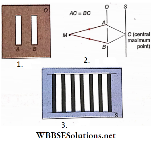
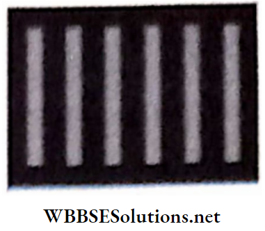
Alternate bright and dark lines can be seen on screen S placed behind O. These alternate dark and bright lines are called interference fringes
Constructive and destructive interferences
Assume that the amplitude of each of the two light waves of the same frequency is A. While propagating in the same direction through a medium they superpose at a point in the medium. The resultant amplitude at the point is equal to the vector sum of the amplitude of the original waves (by the principle of superposition of waves). If superposition takes place in the same phase, then the resultant amplitude = A + A = 2A.
As intensity is directly proportional to the square of amplitude, the resultant light will be four times as intense as the individual wave. This is called constructive interference. On the other hand, if superposition takes place in opposite phases, the resultant amplitude = A-A = 0 and the intensity of light is also zero. This is called destructive interference
If the phase difference or phase relation between two waves remains the same then the interference pattern at every point of the medium remains the same.
It may be noted that destructive interference does not imply the destruction of energy. No loss of energy takes place, only the energy of the dark points is transferred to that of the bright points so that the total energy of the incident waves remains constant. In other words, there is only redistribution of light energy over the region of superposition.
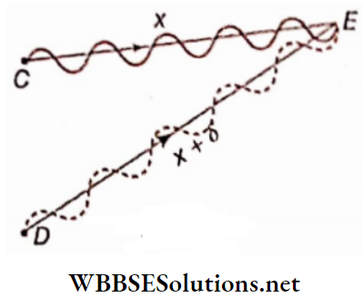
Light interference class 12 notes Analytical treatment of interference:
Let c and D be two sources of monochromatic light. The amplitude of each wave = A, wavelength = λ and speed = c.
Two light waves A moving in the same direction superpose at the point E. The A resultant displacement of point E due to superposition is the 1 algebraic sum of two individual displacements produced by the J two waves.
Distances of the point E from the two sources are x and (x+ δ), respectively. So the path difference of the waves at that point is δ . If y1 and y2 are the displacements of point E due to the waves produced from sources C and D In time t
⇒ \(y_1=A \sin \frac{2 \pi}{\lambda}(c t-x)\)
⇒ \(y_2=A \sin \frac{2 \pi}{\lambda}[c t-(x+\delta)]\)
The resultant displacement of point E
y = y1+ y2
⇒ \(A\left[\sin \frac{2 \pi}{\lambda}(c t-x)+\frac{\sin 2 \pi}{\lambda}\{c t-(x+\delta)\}\right]\)
⇒ \(2 A \sin \frac{2 \pi}{\lambda}\left\{c t-\left(x+\frac{\delta}{2}\right)\right\} \cdot \cos \frac{\pi \delta}{\lambda}\)
⇒ \(\sin C+\sin D=2 \sin \frac{C+D}{2} \cdot \cos \frac{C-D}{2}\)
Or, \(y=A^{\prime} \sin \frac{2 \pi}{\lambda}\left\{c t-\left(x+\frac{\delta}{2}\right)\right\}\) …………………. (2)
Where A’ = 2A \(\cos \frac{\pi \delta}{\lambda}\) …………………. (3)
The sine function in equation (1) suggests that the resultant wave is also a wave of velocity c and wavelength A.
Again equation (2) shows, that the amplitude A’ of the resultant wave is not equal to the amplitude of the two superposing waves but modified by their path difference δ.
1. Condition for destructive interference:
If \(\delta=\frac{\lambda}{2}, \frac{3 \lambda}{2}\), \(\frac{5 \lambda}{2}\) ….. = \((2 n+1) \frac{\lambda}{2}\) (where n = 0 or any integer), \(\cos \frac{\pi \delta}{\lambda}\) = 0 and hence A’ = 0 and hence A’ = 0. Amplitude being zero
Intensity is also zero. Thus at points where the path difference between the waves are odd multiples of, the intensity of light is zero. These points are dark points. The two waves produce destructive interference at such points. This phase difference between the two waves at points where destructive interference takes place is
⇒ \(\Delta \phi=\frac{2 \pi}{\lambda}(2 n+1) \frac{\lambda}{2}=(2 n+1) \pi\)
∴ [since phase difference, path difference ]
2. Condition for constructive interference:
If = 0 , \(\frac{2 \lambda}{2}\), \(\frac{4 \lambda}{2}, \ldots=2 n \frac{\lambda}{2}\)(where n = 0 or any integer) that is A’ = 2A . Amplitude is the highest, and intensity is also the maximum.
Thus at points where the path difference between the waves is an even multiple of y the intensity of light is maximum. These points are bright points. Two waves produce constructive interference at these points
Thus the difference between the two waves at points where conNtrnctlvc Interference takes place Is
⇒ \(\Delta \phi=\frac{2 \pi}{\lambda} \cdot \frac{2 n \lambda}{2}\) = 2n
It Is to be noted that, point E is not a single point that satisfies equation (1). That Is, either of the conditions of destructive and constructive interference is obeyed not only at a single point In space but for a set of points.
The locus of the point E is, In general, hyperbolic. But when E is at a large distance from the sources C and D, compared to their mutual distance CD, the locus of E is effectively a straight line.
As a result, dark and bright straight lines are obtained instead of dark and bright points, due to destruc¬ tive and constructive interference, respectively. These are called dark and bright interference fringes
Interference of light physics class 12 Important Definitions in Light Interference
Intensity:
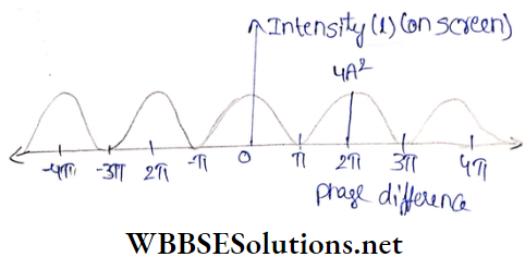
Clearly, interference of two waves results in a variation of intensity of light at different points. The amplitude of the resultant wave, A’ = 2A cos \(\cos \frac{\pi \delta}{\lambda}\) and therefore A’ can vary from 0 to ±2A.
As intensity is directly proportional to the square of amplitude, the value of intensity increases from 0 to 4A². That is maximum intensity can be four times the intensity of a single wave. IfI is the intensity at a point on the screen then,
I∝ A’²
⇒ \(4 A^2 \cos ^2 \frac{\pi \delta}{\lambda}\)
Or, I = \(k 4 A^2 \cos ^2 \frac{\pi \delta}{\lambda}\)
Or, \(I_0 \cos ^2 \phi\)
Io= 4A²k, (is the maximum intensity) and \(\frac{\pi \delta}{\lambda}\)
Hence the intensity in the region of superposition follows the cosine-squared rule. Variation of intensity with phase difference is shown below
1. Let waves coming from two coherent sources of equal frequency be of amplitudes A1 and A2, intensities I1 and 12 with phase difference Φ.
1. On the superposition of two coherent waves, the expression for resultant amplitude is
⇒ \(A^{\prime 2}=A_1^2+A_2^2+2 A_1 A_2 \cos \phi\)
2. As intensity is directly proportional to the square of amplitude, the resultant intensity is
I = \(I_1+I_2+2 \sqrt{I_1 I_2} \cos \phi\)
⇒ \(I_{\max }=I_1+I_2+2 \sqrt{I_1 I_2}=\left(\sqrt{I_1}+\sqrt{I_2}\right)^2\)
And \(I_{\min }=\dot{I}_1+I_2-2 \sqrt{I_1 I_2}=\left(\sqrt{I_1}-\sqrt{I_2}\right)^2\)
3. Moreover, as the amplitude of bright fringe = A1+ A2 and amplitude of dark fringe =|A1A2|
⇒ \(\frac{I_{\max }}{I_{\min }}=\frac{\left(A_1+A_2\right)^2}{\left(A_1-A_2\right)^2}\)
2. If the sources are not coherent, the resultant intensity at any point will just be the sum of the intensities of the individual waves
Conditions of sustained interference:
- Two light sources must be monochromatic and should emit waves of the same wavelength.
- The amplitude of the waves should be equal or nearly equal.
- There must always be a constant phase difference between the two waves. With the change in phase of any wave there: should be a simultaneous change in the other to the same extent.
- Such pair of sources are called coherent sources
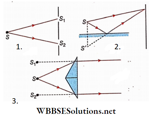
Formation of Coherent Sources
It has already been stated that for sustained interference, a pair of coherent sources is necessary. When sources are not coherent, the intensity at any point changes so rapidly that no interference fringe is observed in practice, and all points appear equally bright
Two similar but separate sources do not form coherent sources. Even two very close points on the same source are not coherent.
Hence there are special methods of creating coherent sources. Some are described below:
- In Young’s double slit experiment, two slits S1 and S2, kept at a fixed distance from light source S, act as coherent sources
- In Lloyd’s single mirror experiment, a thin illuminated slit S and its virtual image, S’, formed due to reflection from a plane mirror, serve as a pair of coherent sources
- In the experiment with Fresnel’s biprism, two virtual images and S2 of a source S, produced by refraction through the biprism 1, act as coherent sources
Explanation of Formation of Interference Fringes
The formation of interference fringes can be explained by the principle of superposition of waves. In Young’s experiment, slits A and B are equidistant from source M. In that case, the secondary sources will also be coherent and hence in phase. Wavefronts from these two sources, propagate one after another
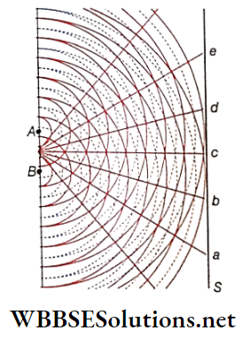
Through the space between the obstacle and the screen. Hence they superpose in solid line arcs to show wavefronts in the same phase. Broken line arcs, in between represent wavefronts in the opposite phase.
Clearly, waves coming from two sources proceeding towards the points a, c and e, superpose in the same phase. Thus amplitude of the resultant wave becomes maximum and constructive interference takes place along the lines leading to the points a, c and e on the screen.
On the other hand, waves are directed towards points b or d, superposing the opposite phase. Thus amplitude of the resultant wave is zero and destructive interference takes place. Therefore, interference fringes consisting of bright and dark lines are displayed on screen S.
The wavelength of monochromatic light be A, the path difference between two waves along the dark lines happens to be odd multiples \(\frac{\lambda}{2}\) of and that along bright lines, even multiples of \(\frac{\lambda}{2}\).
1. If white light is taken instead of monochromatic light in Young’s double slit experiment, the central bright fringe will be white and bright-coloured fringes will be observed on either side of the central fringe. This is because wavelengths of the colours, forming white are different and therefore each one produces its characteristic interference fringe pattern. Thus fringes of different colours are produced.
As the central line of the interference pattern is equidistant from each of the two coherent sources; the light of all component colours reaches phase and a bright white light is formed at that point.
2. The fringes disappear when one of the slits A or B is covered by an opaque plate and the screen gets illuminated with a uniform intensity.
3. If one of the slits is covered with translucent paper, fringes of the same width will be formed. But the bright band will look less bright and the dark band will look less dark.
Interference of light physics class 12 Width of interference fringes
In A and B are two coherent sources of monochromatic light, S is a screen, 2d = distance between A and B, O is the mid-point of AB, and D = perpendicular distance of AB from the screen. As AC = BC, waves starting from two of the sources in phase reach point C in phase. Hence, the resultant amplitude as well as intensity at C is maximum.
All points on the line perpendicular to the plane of the paper and passing through C will be equidistant from the I sources A and B. Thus a central bright fringe is formed which is a straight line.
Now a point P is taken at a distance x from C i.e., CP = x; AP and BP are joined. As the lengths of two paths are not equal there will be a phase difference between the waves reaching P from A and B. Thus whether constructive or
Destructive interference will take place at point P depending on the path difference between the two incoming waves
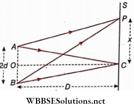
From the
BP² = D² + (x+ d)² and AP² = D² + (x-d)²
BP² – AP² = (x+ d)²- (x-d)² = 4xd
Or, Bp- Ap = \(\frac{4 x d}{B P+A P}=\frac{4 x d}{2 D}=\frac{2 x d}{D}\) ……………… (1)
[Since D»d hence BP = AP ~D]
This path difference between the two waves in reaching P
Bp -Ap = \(\frac{2 x d}{D}\)
By the condition of interference, for n -th bright fringe at P, path difference
⇒ \(\delta=\frac{2 x_n d}{D}=2 n \cdot \frac{\lambda}{2}\) [n = 0, 1, 2……]
Or, \(\frac{D n \lambda}{2 d}\) ……………. (2)
xn is the distance of n -th bright fringe on either side of C] Taking n = 1, 2, 3 …, the positions of 1st, 2nd, 3rd etc. bright fringe, on either side of the central bright fringe, can be found out
For (n + 1) -th bright fringe
⇒ \(x_{n+1}=\frac{D(n+1) \lambda}{2 d}\) …………… (3)
So, the distance between two consecutive bright fringes
= \(x_{n+1}-x_n=\frac{D(n+1) \lambda}{2 d}-\frac{D n \lambda}{2 d}=\frac{D}{2 d} \cdot \lambda\)
By the condition for the formation of the n -th dark fringe at P is
⇒ \(\delta=\frac{2 x_n d}{d}=(2 n+1) \frac{\lambda}{2} \text { or, } x_n=\frac{D}{2 d}(2 n+1) \frac{\lambda}{2}\)
Taking n = 0, 1, 2 etc, positions of 1st, 2nd, 3rd, etc., dark fringes on either side of the central bright fringe can be found out
Hence for (n + 1) -th dark fringe
⇒ \(x_{n+1}=\frac{D}{2 d}\{2(n+1)+1\} \frac{\lambda}{2}\) ………………………….. (6)
Hence the distance between two consecutive dark fringes
= \(x_{n+1}-x_n=\frac{D}{2 d}\{2(n+1)+1\} \frac{\lambda}{2}-\frac{D}{2 d}(2 n+1) \frac{\lambda}{2}\)
= \(\frac{D}{2 d} \cdot \lambda\) ………………………….. (7)
Thus the distance between two consecutive bright or dark fringes is the same. This distance is called fringe width. Therefore if y is the fringe width then,
= \(\)………………………….. (8)
It is clear from equation (8) that
- Since there is no ‘n’ in the expression of y, it can be said that fringe width does not depend on the order of the fringe. All hinges are of the same width.
- Fringe width is directly proportional to the wavelength of light used. For a greater wavelength, fringe width increases, i.e., fringes will be wider. Similarly, for shorter wavelengths, fringes will be thinner.
- If the value of D is large, the fringe width will Increase.
- If the value of d is small, the fringe width will Increase.
Also If the total experiment is conducted In any other medium, wavelength decreases (\(\lambda^{\prime}=\frac{\lambda}{\mu}0\) ). Hence, fringe width decreases.
Further, in whichever position the screen is placed In front of sources A and D, the interference pattern is always observed. As interference patterns are not restricted to a fixed place, these are called non-localised fringes.
Angular fringe width
If the angular position of the n-th fringe on the screen be Qn then,
⇒ \(\theta_n=\frac{x_n}{D}=\frac{\frac{D n \lambda}{2 d}}{D}=\frac{n \lambda}{2 d}\)
For (n + 1) -th fringe , \(\theta_{n+1}=\frac{(n+1) \lambda}{2 d}\)
So, the angular separation between two successive fringes i.e., the angular width of the fringe
⇒ \(\theta=\theta_{n+1}-\theta_n=\frac{(n+1) \lambda}{2 d}-\frac{n \lambda}{2 d}=\frac{\lambda}{2 d}\) …………………………………………… (9)
The angular width of the fringe does position of the screen
Angular width decreases with the Increase of the separation between the coherent sources and vice versa. 0 = R)
If the entire experiment Is performed Inside any liquid (refractive Index for say), the angular width decreases
Optical path
The equivalent optical path of the distance covered by a certain monochromatic light through a certain medium In a certain interval of time Is the path covered by light In the same Interval of time through a vacuum.
Suppose, the refractive Index of a medium for a certain monochromatic ray Is fi. The velocity of the ray In that medium Is v.
⇒ \(\frac{c}{v}\) Or, c= v ………………………………….. (10)
Where, c – velocity of light In vacuum]
Now If the said monochromatic light takes time t to travel through the said medium then,
v = \(\frac{x}{t}\)
And If light can travel distances in the same Interval of time through a vacuum then
c = \(\frac{l}{t}\)
Hence from equation (10), we get
⇒ \(\frac{l}{t}=\mu \cdot \frac{x}{t}\)
Or, l = μ. x
Here l, according to the definition of optical path, Is the equivalent optical path of x.
For more than one medium, we can write optical path
l = \(\Sigma \mu_i x_i\)
Displacement of fringes due to the introduction of a thin plate:
A and H are two monochromatic, coherent sources of light, S’ It the screen, the 2d distance between A and U, 0 is the midpoint of AB, and Dr I perpendicular distance of All front of the screen.
Waves coining from two coherent sources produce an Interference pattern on the screen. Generally, point C Is the position of the central bright fringe as AC = BC. A point P Is considered on the screen. Now a glass plate is introduced perpendicularly in the path AP. Let its thickness be t and the refractive index of glass he mm. it results in the shifting of the entire fringe along with its central fringe.
This is caused by the difference in the velocity of light in air and glass
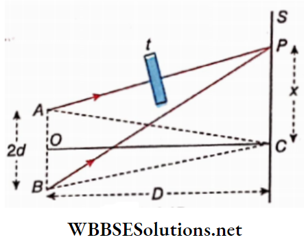
While moving from A to P, light travels a path (AP-t) through air (ft = 1) and a path t through glass
Hence optical path from A to P= (AP-t). 1+μ. 1
= Ap + t (-1)
Differences in optical paths from the points A and B
δ = Bp- Ap- t(μ-1)
= (Bp- Ap)- t(μ-1)
= \(\frac{2 x d}{D}-t(\mu-1)\)
If P is at the centre of n -th bright fringe
= \(\delta=2 n \cdot \frac{\lambda}{2}=n \lambda\) , where n = 0,1,2……..
= \(\frac{2 x d}{D}-t(\mu-1)=n \lambda\)
Or, x = \(\frac{D}{2 d}\{n \lambda+t(\mu-1)\}\)
Hence, because of the presence of a glass plate, a distance of n -th bright fringe from C, x = \(\frac{D}{2 d}\{n \lambda+t(\mu-1)\}\). Putting n = 0 in this equation we get the displacement of the central bright fringe due to the insertion of the plate
Let the displacement be x0
⇒ \(x_0=\frac{D}{2 d}(\mu-1)\)t
The refractive index of glass p is greater than 1, hence xQ is positive, i.e., the central bright fringe will move further from C towards the glass plate.
Putting n = 1, displacement of the 1st bright fringe l.e., xl is obtained.
∴ \(\frac{D}{2 d}\{n \lambda+t(\mu-1)\}\)
∴ Fringe width
y = \(x_1-x_0=\frac{D}{2 d}\{\lambda+(\mu-1) t\}-\frac{D}{2 d}(\mu-1) t=\frac{D}{2 d} \cdot \lambda\)
It proves that though a displacement occurs In fringe pattern due to introduction of a glass plate, fringe width remains unaltered
⇒ \(\frac{y}{\lambda}=\frac{2 D}{d}\) …………. (12)
From equations (11) and (12),
⇒ \(x_0=\frac{y}{\lambda}(\mu-1) t\) …………. (13)
If x0,y, t and A are known, the refractive index p of the material of the plate can be found out from equation (13).
Also if p is known, t can be calculated out.
Due to the introduction of the glass plate, if the central bright fringe shifts a distance equal to the length of m bright fringes, then
⇒ \(x_0=m y \quad \text { or, } \quad \frac{y}{\lambda}(\mu-1) t=m y\)
Or, \((\mu-1) t=m \lambda\)
Or, m = \(\frac{(\mu-1) t}{\lambda}\)
This equation gives the equivalent number of fringe width by which a displacement of total fringe pattern occurs.
Interference of light physics class 12
Light Wave And Interference Of Light Interference Of Light Numerical examples
Example 1. A screen is placed at a distance of 5 cm from a point source. A 5 mm thick piece of glass with a refractive index of 1.5 is placed between them. What is the length of the call path between the source and the screen
Solution:
Length of air path between the source and screen = 5 – 0.5 = 4.5 cm
Airpath, equivalent to path through the glass plate
= Refractive index x thickness = 1.5 × 0.5 = 0.75 cm
length of optical path = 4.5 + 0.75 = 5.25 cm
Example 2. Two straight and parallel slits, 0.4 ap-ft sraOhiminated by a source of monochromatic light. Interference pattern of fringe width 0.5 mm I* produced 40 cm away from the sUts. Find the length of the light used.
Solution:
In this case 2d = 0.4 mm = 0.04 cm , y= 0.5 mm = 0.05cm, D = 40 cm
We know, the fringe width,
y = \(\frac{\lambda D}{2 d}\)
⇒ \(\lambda=\frac{2 d \cdot y}{D}=\frac{0.04 \times 0.05}{40}\)
5 × 10⁻⁵ cm
= 5000 × 10-8cm = 5000 A°
Real-Life Scenarios in Light Interference Experiments
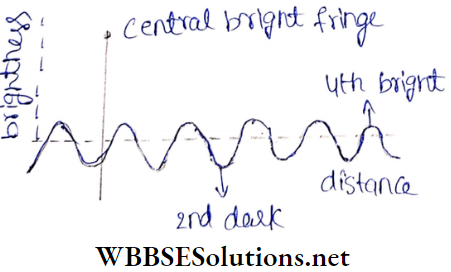
Example 3. In Young’s double-slit experiment on interference, the distance between two vertical slits was 0.5 mm and the distance of the screen from the plane of slits was 100 cm. It was observed that the 4th bright band was 2.945 mm away from the second dark band. Find the wavelength of light used.
Solution:
From it is observed that the distance between the second dark band to 4th bright band = 2.5 x bandwidth. If bandwidth or fringe width is y then,
2.5 × y = 2.945
⇒ \(\frac{2.945}{2.5}\)
= 1.178 mm
As, \(=\frac{D \lambda}{2 d}\)
So, \(\lambda=\frac{2 d \cdot y}{D}=\frac{0.05 \times 0.1178}{100}\)
= 5890 × 10-8 cm = 5890 A°
Example 4. Monochromatic light of wavelength 6000A° was used to set up interference fringes. On the path of one of the interfering waves, a mica sheet 12 × 10-5 cm thick was placed when the central bright fringe was found to be displaced by a distance equal to the width of a bright fringe. What is the refractive index of mica?
Solution:
On placing the mica sheet, if the central bright fringe shifts by the distance of m number of bright fringes then
(μ-1)t = mλ
Here, m = 1, λ = 6000 A° = 6000 × 10-8 cm
t = 12× 10-5 cm
((μ-1) ×12× 10-5
= 1× 6000 × 10-8
Or, (μ-1) = \(\frac{1}{2}\)
Or, mm = 1.5
Example 5. A ray of light of wavelength 6 × 10⁻⁵cm, after passing through two narrow slits, 1mm apart, forms interference fringes on a screen placed lm away. Find the list between two successive bright bands Of the fringes.
Solution:
The distance between two successive bright bands is the fringe width
Width of the fringe \(, \lambda=6 \times 10^{-5}\)
D = 1m, λ = 6 × 10⁻⁵ cm
0.06cm
Example 6. In a double-slit experiment using monochromatic a screen at a light, interference fringes are formed at a particular distance from the slits. If the screen is moved towards the slits by 5 × 10⁻² m, then the fringe width changes by 3 × 10⁻²m. If the distance between the two slit is 10-3m, then determine the wavelength of the light used
Solution:
Fringe width , y = \(\frac{\lambda D}{2 d}\)
Here, A is the wavelength of light used, D is the distance of the screen from the slits, 2d is the separation between the slits. Here screen distance changes by ΔD and fringe width changes by Δy
\(\Delta y=\frac{\lambda \Delta D}{2 d}\)Or, \(\lambda=\frac{\Delta y 2 d}{\Delta D}\)
Now , \(\Delta y=3 \times 10^{-3} \mathrm{~m}, 2 d=10^{-3} \mathrm{~m}, \Delta D=5 \times 10^{-2} \mathrm{~m}\)
λ = \(\frac{3 \times 10^{-5} \times 10^{-3}}{5 \times 10^{-2}}\)
= 6 × 10-2
= 6000 A°
Class 12 Physics Light Interference Notes
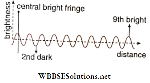
Example 7. In Young’s double slit experiment, the width of the fringe is 2.0 mm. Find the distance between the 9th bright band and the 2nd dark band.
Solution:
It is seen from the distance of the 9th bright band from the second dark band
= 7.5 × width of fringe = 7.5 × 0.2 cm = 1.5 cm
Example 8. Using light of wavelength 600 nm in Young’s double slit experiment 12 bands are found on one part of the screen. If the wavelength of light is changed to 400 nm, then what will be the number of bands on that part of the screen?
Solution:
In wavelength, λ1 = 600 nm = 600 × 10-9 m; the number of fringes, n1 = 12, fringe width y1 In the second case, wavelength, λ2 = 400 nm = 400 × 10-9 m’ number of fringes n2 and fringe width y2 first case, sucLet the distance between the slits and the screen be D, separation between the slits be 2d and length of the entire fringe pattern be x.
Now \(\frac{\lambda_1 D}{2 d}=\frac{600 \times 10^{-9} D}{2 d}\)
And n1 = \(\frac{x}{y_1}\)
Or, = \(12=\frac{x \times 2 d}{600 \times 10^{-9} D}\)
or x = \(\frac{12 \times 600 \times 10^{-9} D}{2 d}\)
Also, y= \(\frac{400 \times 10^{-9} D}{2 d}\)
n2 = \(\frac{x}{y_2}=\frac{12 \times 600 \times 10^{-9} D \times 2 d}{2 D \times 400 \times 10^{-9} D}\)
= 18
Example 9. The green light of wavelength 5100 A° from- a narrow slit is incident on a double slit. The overall separation of 10 fringes on a screen 200 cm away is 2 cm, find the separation between the slits
Solution:
Width of 10 fringes, x = \(\frac{D}{2 d} \lambda\)
= 2 cm
Here, D = distance of this screen = 200 cm, 2d = separation between the two slits, λ= wavelength of light = 5100A°
= 5100 × 10-8cm
2d = \(10 \frac{D}{x} \lambda=\frac{10 \times 200 \times 5100 \times 10^{-8}}{2}\)
= 51 × 10-3 = 0.051 cm
Example 10. The ratio of the intensities between two coherent light sources used in youngs double slit experiment, is n. Find the ratio of the intensities of the principle maximum and minimum of the band.
Let the intensities of the sources be I1 and I2 According to question, I1 = nI2
Now, if Imax and Imin are the intensities of central maximum and minima respectively then
⇒ \(\frac{\left(\sqrt{I_1}+\sqrt{I_2}\right)^2}{\left(\sqrt{I_1}-\sqrt{I_2}\right)^2}=\frac{\left(\sqrt{n} \cdot \sqrt{I_2}+\sqrt{I_2}\right)^2}{\left(\sqrt{n} \cdot \sqrt{I_2}-\sqrt{I_2}\right)^2}\)
= \(\frac{(\sqrt{n}+1)^2}{(\sqrt{n}-1)^2}=\frac{n+1+2 \sqrt{n}}{n+1-2 \sqrt{n}}\)
Example 11. In Young’s experiment, with a monochromatic light of wavelength 5890 A°, the seats are separated by a distance of 1mm. Find the angular width between two sucessive interference fringes
Solution:
Here, ,1 = 5890 A° = 5890 × 10-8cm and 2d = 1mm
= 0.1 cm
Angular width between two successive bright or dark bands
= \(\frac{\lambda}{2 d}=\frac{5890 \times 10^{-8}}{0.1}\) radian
= \(5890 \times 10^{-7} \times \frac{180}{\pi}\)
= 0.03 degree
Example 12. In Young’s double slit experiment, the angular width of a fringe formed on a distant screen is 0.1 0. The wavelength of the light used in the experiment is 6000A. What is the distance between the two slits?
Solution:
We know, the angular width of a fringe,
⇒ \(\theta=\frac{\lambda}{2 d}\)
= \(\frac{\lambda}{\theta}=\frac{6000 \times 10^{-10}}{\frac{\pi}{180} \times 0.1}=\frac{6000 \times 180 \times 10^{-10}}{\frac{22}{7} \times 0.1}\)
= 3.44 × 10⁻³ m
∴ Distance between the slits = 3.44 × 10⁻⁴m
Examples of Applications of Light Interference
Example 13. In the experiment, the path difference between two Interfering waves at a point on the screen is 167.5 times the wavelength of the monochromatic light used. Is the point dark or bright? If the path difference is 0.101 mm, find the wavelength of light used.
Solution: Path difference
167.5 = \(335 \times \frac{\lambda}{2}\)
Wavelength of light
As the number 335 is odd So the point in Question is darkpoint
Here, \(\frac{28}{335}=\frac{2 \times 0.101}{335}\)
⇒ \(6.03 \times 10^{-4}\)
= \(6.03 \times 10^{-4}\) x 107 A = 6030 A
Class 12 physics light interference notes
Example 14. The optical path traversed by a monochromatic ray of light are same while the ray either passes through a distance of 4 cm in glass or a distance of 4.5 cm in water. What is the refractive index of water if that of glass is 1. 53?
Solution:
As the optical path is the same in both cases.
So, μgxg= μwxw
Here, xg = distance travelled through glass and xw = distance travelled through water.
Or, \(\mu_w=\mu_g \cdot \frac{x_g}{x_w}\)
= \(1.53 \times \frac{4.0}{4.5}\)
= 1.36
Refractive index of water = 1.36
Light Wave And Interference Of Light Very Short Question And Answers
Waves and Wavefronts
Question 1. At what angle does a ray of light remain inclined to the wavefront?
Answer: \(\left[\frac{\pi}{2}\right]\)
Question 2. What will be the nature of the wavefront of light emitted from a line source?
Answer: Cylindrical
Question 3. Can two wavefronts of same wave cut each other?
Answer: No
Question 4. A plane wavefront is incident on a prism. What will be the nature of emergent wavefront?
Answer: Plane
Question 5. What is the relationship between the intensity and amplitude of a wave
Answer: Intensity is the square of amplitude
Question 6. If the path difference is A, what will be the phase difference?
Answer: 2 π
Question 7. Do the two electric bulbs connected to the same electric supply line behave as coherent sources?
Answer: No
Question 8. What is the path difference between two waves for constructive interference?
Answer: 2n\(\) n = 0,1,2…..
Question 9. What is the path difference between two waves for destructive interference?
Answer: \((2 n+1) \frac{\lambda}{2}\):, n – 0,1,2…..
Question 10. What is the most important condition for interference of light
Answer: The two light sources must be coherent
Question 11. If Young’s double slit experiment is performed by using a source of white light, then only white and dark fringe patterns is seen. Is the statement true or false?
Answer: False
Question 12. What change will you observe if the whole arrangement used in youngs double slit expeiment is immersed in water
Answer: Fringe lines become narrower
Question 13. For which colour oflight, in Young’s double slit experiment, will the fringe width be minimum?
Answer: For violet light
Question 14. In Young’s double slit experiment, if the distance between the two sources is increased, how will the fringe width be changed?
Answer: The width of wringer would be reduced
Question 15. Does interference of light give any information about the nature of light waves? (whether it is longitudinal or tranverse)
Answer: No
Question 16. What is the phase difference between two points situated on a wavefront
Answer: Zero
Light Wave And Interference Of Light Fill In The Blanks
Question 1. The source of a spherical wavefront is____________________
Answer: A point source
Question 2. If a spherical wavefront is propagated up to infinite distance, then a part of that wavefront is called _________________ front
Answer: Plane
Question 3. Two coherent monochromatic light sources produce constructive interference when the phase difference between them is_____________
Answer: 2nπ
Question 4. In case of interference oflight, when the path difference is odd multiplies of half wavelength, then_______ interference takes place _____________
Answer: Destructive
Question 5. In case of interference of light ____________ remains conserved
Answer: Energy
Question 6. If the distance between the two slits in Young’s double slit experiment is halved and the distance between the slit and the screen is doubled then the fringe width will be_ times the previous fringe width
Answer: Four
Question 7. If the light of a smaller wavelength is used in Young’s double slit experiment, then fringe width will be
Answer: Decreased
Question 8 . In Young’s double slit experiment, if a glass plate is placed perpendicular to the direction of propagation oflight, there will be a _________________ of interference fringe, and there would be in the fringe width
Answer: Displacement, No Change
Question 9. In Young’s double slit experiment, if a glass plate is placed perpendicular to the direction of propagation oflight, there will be a ______________________of interference fringe, and there would be in the fringe width
Answer: Number of fringes
WBCHSE physics class 12 light interference
Light Wave And Interference Of Light Assertion Reason Type
Direction: These questions have statement 1 and statement 2. of the four choices given in below, choose the one best describes the two statements
- Statement 1 is true, statement 2 is true, and statement 2 is a correct explanation for statement 1.
- Statement 1 is true, statement 2 is true, and statement 2 is not a correct explanation for statement 1.
- Statement 1 is true, statement 2 is false.
- Statement 1 is false, statement 2 is true
Question 1.
Statement 1: A ray of light entering from glass to air suffers from a change in frequency.
Statement 2: The velocity of light in glass is less than that in
Answer: 4. Statement 1 is false, statement 2 is true
Question 2.
Statement 1: If the phase difference between the tight waves passing through the slits in the Young’s experiment is n -radian, the central fringe will be dark.
Statement 2: Phase difference is equal to \(\frac{2 \pi}{\lambda}\) times the ath difference.
Answer: 2. Statement 1 is true, statement 2 is true, and statement 2 is not a correct explanation for statement 1.
Question 3.
Statement 1: Interference obeys the law of conservation of energy.
Statement 2: The energy is redistributed in case of interference.
Answer: 1. Statement 1 is true, statement 2 is true, and statement 2 is a correct explanation for statement 1.
Question 4.
Statement 1: When the apparatus in Young’s double slit experiment is immersed in a liquid the fringe width will increase
Statement 2: The wavelength oflight lh a liquid is a lesser titan than in air. That is \(\lambda^{\prime}=\frac{\lambda}{\mu}\)
Answer: 4. Statement 1 is false, statement 2 is true
Question 5.
Statement 1: Interference pattern is obtained on a screen due to two identical coherent sources of monochromatic light. The intensity at the central part of the screen becomes one-fourth if one of the sources is blocked.
Statement 2: The resultant intensity is the sum of the intensities due to two sources.
Answer: 3. Statement 1 is true, statement 2 is false.
Question 6.
Statement 1: If the two interfering waves have Intensities in the ratio 9: 4, the ratio of maximum to minimum amplitudes becomes 3:2
Statement 2: Maximum amplitude = A1+A2 amplitude = A1-A2
Also \(\frac{I_1}{I_2}=\frac{\left(A_1\right)^2}{\left(A_2\right)^2}\)
Answer: 4. Statement 1 is false, statement 2 is true
Light Wave And Interference Of Light Match The Column
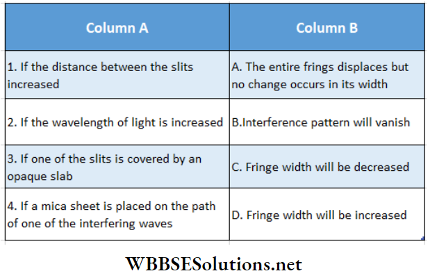
Question 1. Match the wavefronts in column 2 with their sources in column 1
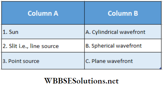
Answer: 1- C, 2-A, 3-B
Question 2.
Answer: 1- C, 2- D, 3-B, 4-A
Question 3.
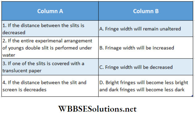
Answer: 1- B, 2- C, 3- A,D,5-C
Question 4. In Young’s double slit experiment the path difference, Ax =(S2P~ S1P). Now a glass slab is placed in front of the slit S2.
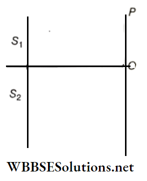
Now from the above information match the columns.
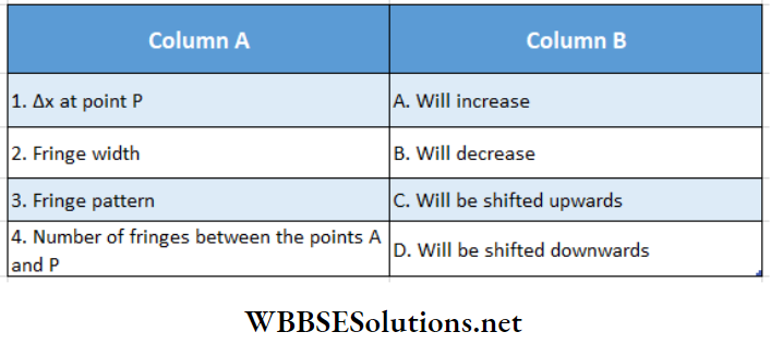
Answer: 1-A, 2-C, 3-E, 4-C
5. Column I shows four situations of Young’s double slit experimental arrangement with the screen placed far away from the slits S1 and S2 . In each of these cases S1P0 = S2P0
S1P1 – S2P2 \(\frac{\lambda}{4}\)
S1P1 – S2P2 \(\frac{\lambda}{3}\)
Where A is the wavelength of the light used. In cases 2, 3 and 4 a transparent sheet of refractive index p and thickness t is pasted on slit S2: The thickness of the sheets are different in different cases. The phase difference between the light waves reaching a point P on the screen from the two slits is denoted by S(P) and the intensity by I(P). Match each situation given in column I with the statement(s) in column valid for that situation
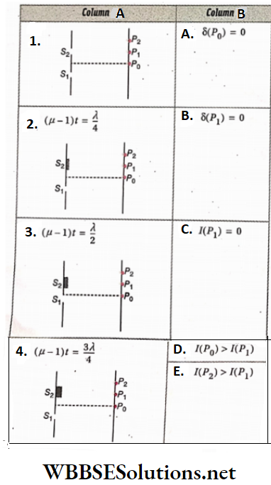
Answer: 1- A,D, 2- B, 3- E, 4- C,D,E
WBCHSE physics class 12 light interference
Light Wave And Interference Of Light Conclusion
1. Light wave is a transverse electromagnetic wave, As a wave generated from a source spreads hr all directions through vacuum or any medium, the locus (line or surface) of the points in the path of the wave in the same phase at any moment constitute a wavefront.
2. According tolUrygens’ principle, each point on a Wavefront acts as a secondary source oflight. It means that from each of these secondary sources secondary wavelets are produced and they spread all around with the same speed, Tire new wavefront at a later stage is simply the common envelope or tangential plane of these wavelets.
3. The principle of superposition of waves is that at any moment the resultant displacement at any point in a medium due to the influence of a number of waves Is equal to the vector sum of the displacements of the component waves at that point.
4. If two light waves having the same amplitude and
Frequency is superposed at any region In a medium the Intensity of the resultant light wave Increases at some points In that region and decreases at some other points. This phenomenon Is known as Interference of light.
The phenomena or Increase hr light Intensity Is called constructive Interference and the decrease In light Intensity Is called destructive interference.
5. To get sustained Interference fringes two coherent sources of light are necessary, 4 Scientist Thomas Young first experimentally demonstrated the Interference of light.
6. In Young’s double-slit experiment, It Is seen that the separation of two consecutive bright or dark hands is equal. This separation Is called fringe width. Fringe width is directly proportional to the wavelength of light
7. Let the two waves
y1 = \(A \sin \frac{2 \pi}{\lambda}(c t-x)\)
y2 = \(\lambda \sin \frac{2 \pi}{\lambda}\{c t-(x+\delta)\}\)
Superpose on each other to form interference. Then the resultant displacement produced at a point Is
y = \(=y_1+y_2=A^{\prime} \sin \frac{2 \pi}{\lambda}\left\{c t-\left(x+\frac{\delta}{2}\right)\right\}\)
Where A’ =\(2 A \cos \frac{\pi \delta}{\lambda}\) and δ – path difference between the two waves
8. For constructive Interference, \(2 n \cdot \frac{\lambda}{2}\)
Phase difference = 2nπ
And for destructive interference, δ = (2n+1) \(\frac{\lambda}{2}\)
Phase difference = (2n+1)π
Where n = 0 or any positive integers
In case of young double slit experiment the fringe width y = \(=\frac{D}{2 d} \cdot \lambda\)
Where D = Perpendicular distance of the screen from the
Plane of two monochromatic sources (slits), 2d = distance between two coherent sources, A = wavelength oflight used. Displacement of fringes due to the introduction of a thin plate on the path of one of the waves,
x = \(\frac{y}{\lambda}(\mu-1) t\)
Where y = fringe width, A = wavelength of light, t = thickness of the plate
Due to the inclusion of a glass plate if the central bright band is shifted through a distance of the previous m -bright bands, then (μ-1)t = mλ