
Ohm’s Law Introduction
An electric current is a flow of charges—which is often carried by electrons through a wire. It can also be carried by ions. Electric current is a physical quantity that can be measured and expressed numerically. The principal function of any source of electricity is to send current in an external circuit. In this chapter, we shall discuss the electric current following Ohm’s law
Ohm’s Law Electromotive Force Or Emf
To maintain the flow of water in a pipe external force is to be applied. Similarly, to maintain the flow of current in a conductor some sort of force is required. The physical quantity supplied by the source of electricity is known as the electromotive force. Force and electromotive force are two different physical quantities. i.e., an electromotive force is really not a force, as understood in mechanics.
In the sources of electricity like electric cell, dynamo etc. when even an external energy is converted to electrical energy, an electromotive force is said to have developed.
Electric Current Notes for WBCHSE
Definition: The amount of electrical energy produced for transferring a unit positive charge from the lower to the higher potential inside an electric source is called the electromotive force or emf of the source i.e.,
electromotive force = \(\frac{amotmt ofelectrical energy}{quantity ofcharge transferred}\)
Unit: According to the above definition the unit of electromotive force is J.C-1. Also, joule/coulomb is known to be equal to volt [see Chapter ‘Electric Potential’]. So the unit of electromotive force is volt (V) which is also the unit of electric potential and potential difference.
The usual definition of electromotive force: When a source of electricity does not send current in an external circuit i.e., when the circuit is open, the potential difference between the two ends of the source is called its electromotive force.
Ohm’s Law Classification Of The Sources Of Electricity
Electric cell: The source of electricity which does not contain any moving machinery inside it is generally called an electric cell. For Example—chemical cells, solar cells, photoelectric cells, and nuclear cells.
Dynamo: The source of electricity which has a moving machinery is called a dynamo. In this chapter, we shall discuss only the chemical cell.
Different Types of Chemical Cells:
1. Primary cell: In this type of cell chemical energy is converted into electrical energy. Since we get electrical energy without the help of any electrical source, it is called a primary cell.
Examples: Voltaic cell, Leclanche cell, dry cell, Daniell cell. The active components of this cell gradually decay if it sends current in the external circuit for some time and ultimately the cell becomes inactive. The electrochemical reactions taking place inside this cell are irreversible. This implies that the inactive components cannot be made active by a reversible process. The cell is to be abandoned unless the components are replaced.
2. Secondary cell: In this type of cell too, chemical energy is converted into electrical energy. But unlike a primary cell, it can be reused several times. For this, the external current source is needed to recharge it.
Example: Lead-acid accumulator, Alkali accumulator.
The active components of this cell gradually decay as the cell sends current in the external circuit. But here the electro-chemical reactions are reversible. With the help of reverse reactions, the inactive components of the cell can be made active again. To start reverse reactions, current from an external source of electricity, having an electromotive force greater than that of the cell, is allowed to pass through the cell.
This cell acts in two steps:
1. Discharging:
The act of sending current in the external circuit by this cell is called discharging of the cell. During discharging chemical energy is converted into electrical energy.
2. Charging:
The act of activating the practically inactive cell by sending a current in it from an external source in the reverse direction is called charging of the cell. During charging, electrical energy is converted into chemical energy.
During charging, electrical energy is converted into energy which is stored in the cell and conveniently can be converted into electrical energy. Hence this cell is also called a storage cell or accumulator.
3. Standard cell:
As long as this cell is active its electromotive force does not change. So compared with the constant value of the emf of this cell, emfs of other cells can be determined or different electrical instruments can be calibrated. This cell is almost never used as a source of electricity. At present the internationally recognized standard cell is the Weston cadmium cell. Emf of this cell at 20°C is 1.01830 V.
Symbol Of a cell: All cells are shown by drawing two parallel lines of unequal lengths. The long line represents the positive pole and the short line represents the negative pole of the cell.
Ohm’s Law Study Guide WBCHSE
Ohm’s Law Ohm’s Law
In the year 1826 German scientist Georg Simon Ohm established the relationship between the potential difference across a conductor and the current through it.
The law states:
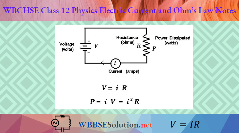
With that temperature and other physical conditions remaining constant, the current flowing through a conductor is directly proportional to the potential difference between its two ends. Let AB be the part of a current-carrying conductor. Also let the potential at A and B be VA and VB respectively, VA being greater than VB. Naturally, current will flow from the point A to the point B. Let the current beI. Then according to Ohm’s law,
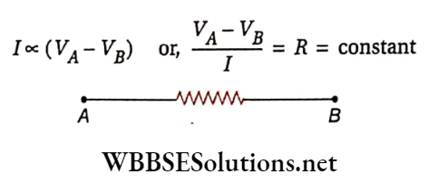
The constant of proportionality R is called the resistance of the conductor.
Let VA – VB = V
∴ \(\frac{V}{I}\) = R
or, V = IR
or, I = \(\frac{V}{R}\)
Each of the Equations (1), (2), and (3) is the mathematical form of Ohm’s law.
Usually, any conductor that offers resistance to the flow of charge carriers in an electric circuit is called a resistor. A resistor is of ten simply called ‘a resistance’.
Ohm’s Law Explained for Class 12
Electrical Resistance:
It is obvious from equation (3) that the potential difference ( V) being constant, the current (l) will decrease with the increase of resistance (R) and vice versa. So, physically it means that resistance is the capacity to change the current in the circuit.
Definition: The resistance of a conductor may be defined as the property of the conductor by virtue of which it opposeÿhe current flowing through it.
Resistances are measured by the ratio of the potential difference between the two ends of a conductor and the current flowing through it.
Unit Of resistance: The unit of resistance is ohm (Ω). So, according to Ohm’s law,
⇒ \(1 \Omega=\frac{1 \mathrm{~V}}{1 \mathrm{~A}}\)
i.e., if 1-ampere current flows through a conductor when subjected to a potential difference of 1 volt then the resistance of that conductor is said to be 1 ohm.
Current-voltage graph (linear and nonlinear):
The change of current (l) due to the change in potential difference (V) across a conductor. Here V is taken in the x-axis and I is taken in the y-axis. The graph OA, clearly a straight line one, is known as a current-voltage graph.
Note that, to change the potential difference across the conductor we practically proceed with the change in applied voltage.
The nature of the graph supports Ohm’s law i.e.,\(I=\frac{1}{R} \cdot V\).
Clearly, \(\frac{1}{R}\) is the slope of the graph. It means the reciprocal of the slope of the I-V graph is the resistance of the conductor. It is an experimental graph from which Ohm’s law can be justified. Hence the conductors that obey Ohm’s law are called ohmic conductors.
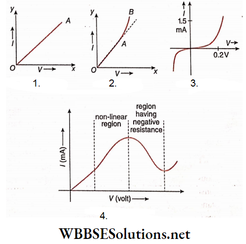
On the other hand, the conductors which do not obey Ohm’s law are known as non-ohmic conductors. The 1-V graphs for these conductors will not be straight lines showing that the relation between current and voltage is non-linear. Some Examples of non-ohmic conduct are electrolytes, semiconductors, vacuum tubes etc.
Some non-linear relations between current and voltage. I-V curve for the good conductor. It is seen that up to a certain range of electric current, the curve is linear (OA), but the curve becomes non-linear at high electric current (AB). An I-V curve was drawn for a semiconductor diode. In this case, the current depends on the sign of the potential difference. On the other hand, the variation of current through gallium arsenide (GaAs) due to the varying potential difference between its ends as shown by the graph in shows that different values of V are possible for the same current
Ohm’s Law Effect Of Different Factors On Resistance
Dimension of the conductor: The resistance offered by a conductor to the flow of current though it is more if the conductor is thin, and if the conductor is long.
Material of the conductor: Resistance depends on the nature of the material of the conductor. Current flows easily through the metals like silver, copper, aluminum, etc. i.e., the cost of these metals is very low. These are called good conduct tors.
Almost all the metals are good conductors. Carbon, although a nonmetal, is a good conductor of electricity. Graphite, gas-carbon, and charcoal (under high pressure) which are the allotropes of carbon are also good conductors.
Air, wood, rubber, plastic, ebonite, cloth etc all nonmetallic substances are bad conductors of electricity and are called insulators, which allow almost no current to pass through them.
It is to be noted that there are a few types of substances other than metals which may be called good conductors of electricity; Examples—are electrolytes, gas under low pressure, semiconductors, etc. Ordinary water is an electrolyte and so it conducts electricity, but pure water is not.
Temperature of the conductor: The resistance of the metallic conductors increases with the rise of temperature. The platinum resistance thermometer is constructed depending on this principle.
On the other hand, when the temperature reaches close to 0K, the resistance of some metallic conductors vanishes. This phenomenon is called superconductivity.
For Example, the resistivity’ of mercury absolutely disappears below about 4.2 K. Currents created in a superconducting ting persist for several years without diminution. The phenomenon is of vast potential importance in technology. The explanation is given by the so-called BCS theory offered in 1957.
It is to be noted that the resistance of electrolytes, carbon, glass, gas maintained at low pressure, semiconductors etc. decreases with the increase in temp
Other factors: The following incidents happen in some special types of conductors.
1. If light is incident on selenium, its resistance decreases. Its resistance decreases further with the increase of the intensity of the incident light
2. If bismuth is placed in a magnetic field, its resistance increases. Its resistance increases further with the increase – of the intensity of the magnetic field.
3. Air bubbles exist in the pores of charcoal. As air is an insulator, the resistance of charcoal is high. If pressure is applied to charcoal, the bubbles within its pores will evaporate and the particles of charcoal will come in close contact with each other. So, the resistance of carbon decreases.
These effects have been utilized in many important practical applications.
WBCHSE Physics Notes on Electric Current
Superconductors: There are some metals or compounds whose resistance becomes zero at certain low temperatures. These substances are called superconductors and that very temperature is called critical temperature.
Above critical temperature, the resistance-temperature graph of any superconductor is just like that of other common metals. But at critical temperature, the resistance of the superconductor suddenly comes to zero.
Dutch physicist Heike Kamerlingli Onnes (1911 AD) has discovered this phenomenon. He showed that below 4.2 K temperature, mercury is a superconductor.
Superconductivity can be found in different substances, e.g., tin, aluminum, various metallic alloys, highly doped semiconductors etc
Resistivity or Specific Resistance:
The resistance of a conductor (R) under constant temperature depends on the length (l), cross-sectional area (A) and material of the conductor
1. Rule of length:
The resistance of a conductor is directly proportional to its length if the area of the cross-section remains same, i.e.,
R oc l, when A is constant
2. Rule of cross-section: The resistance of a conductor is inversely proportional to its area of cross-section if the length of the conductor remains unchanged, i.e.,
R oc \(\frac{1}{A}\), whenl is constant
⇒ \(R \propto \frac{l}{A} \text { or, } R=\rho \cdot \frac{l}{A}\)….(1)
Here, p is the constant of proportionality, called resistivity or specific resistance of the material of the conductor. Its value depends on the material of the conductor.
If l = 1 and A = 1 then from equation (1) it is obtained
R = p.
i.e., the resistance of the conductor becomes numerically equal to its resistivity when both l and A are in unity. This leads to the definition of resistivity
Definition: The electrical resistance of a conductor of unit cross-sectional area and unit length is defined as the resistivity of the material of the conductor.
Unit of resistivity:
As \(\rho=\frac{R A}{l}\)
⇒ \(\text { unit of } \rho=\frac{\mathrm{ohm} \cdot \mathrm{cm}^2}{\mathrm{~cm}}=\mathrm{ohm} \cdot \mathrm{cm}(\Omega \cdot \mathrm{cm})\)
If length is expressed in meters, the SIunitis ohm-meter (Ωm).
1 Ω m = 1Ω.100 cm
= 100Ω.cm
For Example, the resistivity of copper at 20°C is 1.76 x 10⁻⁶ Ω.cm means that resistance across a copper conductor of cross-sectional area 1cm2 and length 1cm at 20°C is 1.76 x 10⁻⁶ Ω.
The resistivity of different substances: The resistivity of a few conductors and insulators at 20°C is given below.
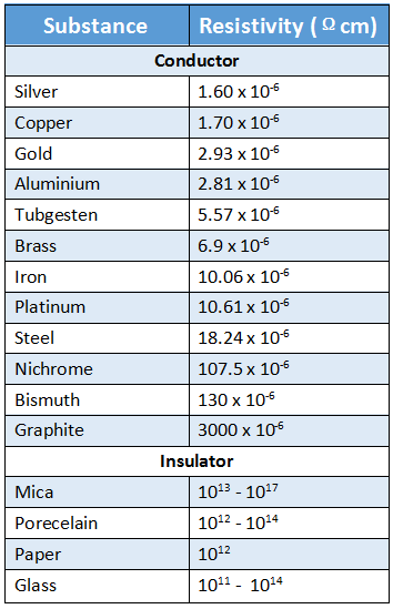
From the above, it appears that the resistivity of silver is the lowest. This means silver is the best-conducting substance. However, since silver os costly, good conductors are mostly made of copper.
Resistivity and conductivity: If an amount of charge Q passes through a conductor In time t, then-current l \(\frac{Q}{t}\). If the length of the conductor Is l, the cross-sectional area is A, and, the potential difference between Us two ends is VA – VB, then
⇒ \(V_A-V_B=I R=\frac{Q}{t} \cdot \frac{\rho l}{A}\)
or; \(Q=\frac{1}{\rho} \cdot \frac{A\left(V_A-V_B\right) t}{l}\)
This relation is Identical to that of the conduction of heal,
⇒ \(Q=\frac{K A\left(T_2-T_1\right) t}{l}\)
So, If \(\frac{1}{\rho}\) is taken as \(\rho\) then \(\rho\) may be analogically called electrical conductivity.
It Is obvious that the two physical quantities, conductivity and resistivity are the reverse of each other.
Hence another way of saying that silver is the best conductor is to say that silver has the least resistivity.
An analogous term conductance has been Introduced as a counter to resistance. The concepts obviously bear reciprocal relation.
The SI unit of conductance is Siemens (S) which was formerly called reciprocal ohm or mho (y). If Y is the conductance, then V = \(\frac{1}{R}\).
As conductance is opposite to resistance, the conductance of a body decreases for the factors for which its resistance increases.
Like resistance, tire conductance of a body depends on its temperature and other physical conditions.
An important comment regarding the magnitude of resistance: Consider a copper wire of length 1 m, cross-sectional area 1 mm² or 0.01 cm². The magnitude of its resistance is
⇒ \(R=\rho \frac{l}{A}=1.76 \times 10^{-6} \times \frac{100}{0.01}=0.0176 \Omega\)
So the resistance of the wire is negligible. If a wire of about 57 m in length having the same cross-section is taken, its resistance will be only 1Ω. So this type of wire cannot be regarded as a resistor. Such wires are used for connecting purposes in an electrical circuit. So it can be taken for granted that the wires that connect different electrical instruments in an electrical circuit have almost no resistance.
Short circuit: The circuit obtained by connecting the two electrodes of a source of electricity directly with the help of a wire having almost no resistance is called a short circuit.
For example, if the positive and the negative terminals of a battery are connected by a copper wire, the wire becomes very hot. As the resistance of such a wire U is very small, the current passing through It is high.
So, there Is a chance of damage to both the connecting wire and the source of electricity. To avoid short circuits, fuse wire Is used In domestic electrical lines.
Ohm’s Law Effect Of Different Factors On Resistance Numerical Examples
Example 1. The length, radius, and resistivity of two wires are each in the ratio 1:3. The resistance of the comparatively thin wire Is . 20 fi. Determine the. resistance of the other wire.
solution:
⇒ \(R=\rho \frac{l}{A}=\frac{\rho l}{\frac{\pi d^2}{4}}=\frac{4 \rho l}{\pi d^2}[d=\text { diameter of the wire }]\)
For the first wire, \(R_1=\frac{4 \rho_1 l_1}{\pi d_{1^{\prime}}^2}\)
For the second wire, \(R_2=\frac{4 \rho_2 l_2}{\pi d_2^2}\)
∴ \(\frac{R_1}{R_2}=\frac{\rho_1}{\rho_2} \times \frac{l_1}{l_2} \times\left(\frac{d_2}{d_1}\right)^2\)
= \(\frac{1}{3} \times \frac{1}{3} \times\left(\frac{3}{1}\right)^2\)
= 1
or R1 = R2
The diameter of the first wire is less. So it is thin
∴ \(R_1=20 \Omega \text {; so } R_2=20 \Omega\)
Example 2. If the length of a copper wire is increased by 0.1%, show that the resistance of the copper wire will increase by 0.2%.
Solution:
If the initial length be, then the final length will be
l2 = l1 x (100.1%)
= \(l_1 \times \frac{100.1}{100}\) = 1.001l1
If the temperature of the wire remains constant, its volume will remain constant.
Now, volume = length x cross-sectional area
So if the length increases from l1 to 1.001 l1 cross-sectional area
A1 decreases to A2, where \(A_2=\frac{A_1}{1.001}\)
Now, \(R_1=\rho \frac{l_1}{A_1} \text { and } R_2=\rho \cdot \frac{l_2}{A_2}\)
∴ \(\frac{R_2}{R_1}=\frac{l_2}{l_1} \times \frac{A_1}{A_2}\)
= 1.001 X 1.001
= 1.002
= 100.2%
i.e., increase of resistance = 0.2%
Alternative Method:
⇒ \(R=\rho \frac{l}{A}\)
By logarithmic differentiation, \(\frac{d R}{R}=\frac{d l}{l}-\frac{d A}{A} \quad(\rho=\text { constant })\)
Now, V = lA = constant
By logarithmic differentiation, \(\frac{d l}{l}=-\frac{d A}{A}\)
Hence, \(\frac{d R}{R}=\frac{2 d l}{l}=2 \times 0.1 \%=0.2 \%\)
Example 3. A lump of copper of mass 10 g and of density 9 g.cm-3 is given. What should be the length and cross-section of the wire made from it so that its resistance is 2cm ohm. (Given, specific resistance of copper 1.8 x 10⁻⁶ Ω.cm)
Solution:
⇒ \(\frac{mass}{density}\) = volume
= length x cross-sectional area
⇒ \(\frac{10}{9}=l A \text { or, } l A=\frac{10}{9}\)…(1)
Again, resistance, \(R=\rho \frac{l}{A} \text { or, } \cdot 2=1.8 \times 10^{-6} \times \frac{l}{A}\)
or, \(\frac{l}{A}=\frac{2}{1.8} \times 10^6=\frac{10}{9} \times 10^6\)…(2)
Now, by multiplying (1) and (2) we get,
⇒ \(l^2=\frac{10}{9} \times \frac{10}{9} \times 10^6 \quad \text { or, } l=\frac{10}{9} \times 10^3 \mathrm{~cm}=11.1 \mathrm{~m}\)
Again dividing (1) by (2) we get, A2 = 10-6
or, A = 10-3 cm2
= 10-1 mm2
= 0.1 mm2
Example 4. A wire of resistance 5Ω is stretched 20%. If the volume remains constant, find the new resistance.
Solution:
The volume of the wire = V = constant. Let the initial length of the wire = l
∴ Initial cross-sectional area, \(A_1=\frac{V}{l}\)
If the length of the wire is increased by 20%
⇒ \(\text { final length }=l \times \frac{120}{100}=1.2 l\)
∴ Final cross-sectional area, \(A_2=\frac{V}{1.2 l}\)
Now, \(R_1=\rho \cdot \frac{l_1}{A_1} \quad \text { and } R_2=\rho \cdot \frac{l_2}{A_2}\)
∴ \(\frac{R_2}{R_1}=\frac{l_2}{l_1} \times \frac{A_1}{A_2}\)
or, \(R_2=R_1 \times \frac{l_2}{l_1} \times \frac{A_1}{A_2}=5 \times \frac{1.2 l}{l} \times \frac{\frac{V}{l}}{\frac{V}{1.2 l}}\)
= 5 X 1.2 X 1.2
= 7.2 Ω
Example 5. A lump of copper Is stretched into a wire 5mm in diameter. Another wire of 1 cm diameter is made from another lump of copper of the same mass. Find the ratio of the resistances of the two wires.
Solution:
5mm = 0.5 cm.
Resistance, \(R=\rho \frac{l}{A}=\rho \frac{V}{A^2}=\frac{\rho m}{D\left(\pi \frac{d^2}{4}\right)^2}=\frac{16 \rho m}{\pi D d^4}\)
Here, \(\rho\) = resistivity, l = length, d = diameter
⇒ \(A=\frac{\pi d^2}{4}\) V = lA = volume,
m = mass, D = \(\frac{m}{V}\) = density
Both the lumps have the same D and p and according to the question, mass m is equal.
∴ \(\frac{R_1}{R_2}=\left(\frac{d_2}{d_1}\right)^4=\left(\frac{1}{0.5}\right)^4=(2)^4=16 \text { or, } R_1: R_2=16: 1\)
Example 6. The length of a wire of cylindrical cross-section is increased by 100%. Find out the percentage change in the resistance, taking into account the consequent decrease in the diameter of the wire.
Solution:
Initial length = l; final length, \(l^{\prime}=l+l \times \frac{100}{100}=2 l\)
If V be the volume, area of cross-section, A = \(\frac{V}{l}\)
∴ Final area of cross-section, \(A=\frac{V}{l}\)
From the formula \(R=\rho \frac{l}{A}\) we get
⇒ \(\frac{R}{R^{\prime}}=\frac{l}{l^{\prime}} \cdot \frac{A^{\prime}}{A}=\frac{l}{2 l} \cdot \frac{V / 2 l}{V / l}=\frac{1}{4}\)
∴ \(R^{\prime}=4 R=R+3 R=R+\frac{300}{100} R\)
i.e., the percentage change in resistance = 300%.
| Class 11 Physics | Class 12 Maths | Class 11 Chemistry |
| NEET Foundation | Class 12 Physics | NEET Physics |
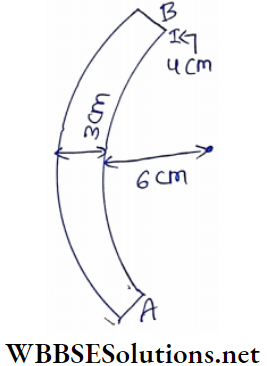
Example 7. What will be the distance of a semicircle between points A and B? Given that radial thickness = 3 cm, axial thickness = 4 cm, Inner radius = 6 cm, and resistivity = 4 x 10⁻⁶ Ωcm.
Solution:
Cross-sectional area, A = 4 cm x 3cm = 12 cm2
Linear length,l = πr = π(6 + \(\frac{3}{2}\) = 7.5 7T cm .
∴ Resistance = \(\rho \frac{l}{A} \quad\left(\rho=\text { resistivity }=4 \times 10^{-6} \Omega \cdot \mathrm{m}\right)\)
⇒ \(\frac{4 \times 10^{-6} \times \pi \times 7.5}{12} \Omega\)
= \(7.85 \times 10^{-6} \Omega\)
Ohm’s Law Carbon Resistors
In electrical experiments, resistances starting from about 0.1 A to 1000 A are widely used. To manufacture these types of resistances, generally, copper or any other conducting metal or alloy are used.
On the other hand in the experiments of electronics, resistances less than 1000 A are seldom used. For these high resistances graphite and gas carbon are widely used nowadays. These are called carbon resistors.
If we observe the table of specific resistance of the conductors, it will be found that the specific resistances of the allotropes of carbon are over a thousand times greater than those of metals.
So carbon is very effective as an element of high resistance. Another advantage is that carbon resistors are cheaper than metal resistors.
Electric Current Basics for WBCHSE Class 12
To manufacture a carbon resistor, a cylindrical shell made of bad conductors was taken. Its length is more or less 1 cm and its diameter is between 2 mm to 5 mm.
Conducting carbon power is introduced in a controlled manner into the shell. The value of the resistance depends on the length and the diameter of the shell and also on the amount of carbon powder.
Two conducting metal wires are taken out from either side of the shell along its axis through which the resistor is connected to the external circuit.
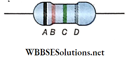
The shell has four different colored rings or bands 4, B, C, and D on its surface. The fourth band D is painted further off with respect to the bands A, B, and C. The resistance of the resistor is obtained from the color of these four bands according to an acknowledged code.
Colour Code of Carbon Resistors:
According to this code, ten single digits from 0 (zero) to 9 correspond to ten colors. The code is as follows:
The first two bands (A and B) represent the first two digits to ascertain their values in ohms. The third band (C) represents the multiplier and the fourth band (D) tolerance.
If A is absent, it will indicate that the tolerance of the resistor is 20%
In some resistors, a 5-band or 6-band coding is used. In these cases, the third band represents the third digit. In that case, the fourth and fifth builds represent the multiplier and tolerance respectively. For a six-banded resistor, the sixth band denotes the temperature coefficient.
The determining digits are shown against color codes in the following table:
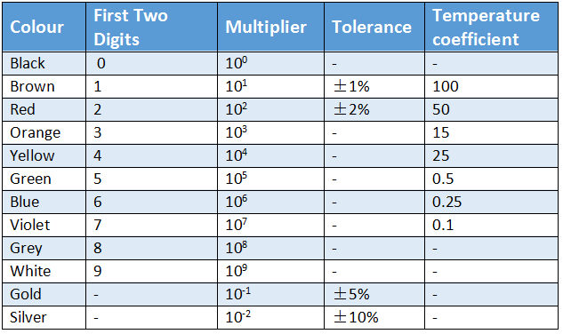
Mnemonics: The sequence of the colour code given above can be remembered by the following sentence, B B ROY of Great Britain has a Very Good Wife wearing.Gold Silver necklace.
Example: Suppose the color bands on a carbon resistor are in the sequence yellow, violet, red and silver.
A: Colouryellow; so from the table, the digit is 4,
B: Colourviolet; so from the table, the digit is 7.
C: Colour red; so from the table, the digit is 2 i.e., the multiplier is 10.
So, the value of the resistance is 47 x 102 or 4700 A.
D: Colour silver; so tolerance is 10%
Hence, the value of the resistance is 4700A± 10% i.e., lies between 4230 A and 5170 A. However in electronics no special importance is given on band D.
Ohm’s Law Carbon Resistors Numerical Examples
Example 1. The equivalent resistance of two cells connected in series and in parallel are \(12 \Omega \text { and } \frac{5}{3} \Omega\) respectively. Calculate the value of each resistance.
Solution:
If R1 and R2 be the two resistances, then equivalent resistance in series combination
R1 +R2 = 12 …..(1)
Equivalent resistance of parallel combination,
⇒ \(\frac{R_1 R_2}{R_1+R_2}=\frac{5}{3} \quad \text { or, } \frac{R_1 R_2}{12}=\frac{5}{3} \quad \text { or, } R_1 R_2=20\)
Now, \(\left(R_1-R_2\right)^2=\left(R_1+R_2\right)^2-4 R_1 R_2\)
= 122 – 4 X 20
= 144 – 80
= 64
or, R1 – R2 = 8 [Here we asuume R1 > R2]…(2)
Adding equations (1) and (2) we have,
2R1 = 20
or, R, = 10Ω
From equation (1) we have,
R2 = I2– R1
= 12- 10
= 2Ω
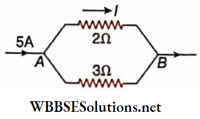
Example 2. A 5-ampere current Is distributed In branches. The ratio of the lengths of the wires in the three branches is 1: 2: 3. Determine the tire magnitude of current in each branch. The material and the cross-sectional area of each wire are the same.
Solution:
Resistance of the wire is proportional to Its length as the material and the cross-sectional area are the same. So we take the resistances as 2a and 3. v and the equivalent resistance as R.
We have
⇒ \(\frac{1}{R}=\frac{1}{x}+\frac{1}{2 x}+\frac{1}{3 x}=\frac{6+3+2}{6 x}=\frac{11}{6 x} \quad \text { or, } R=\frac{6 x}{11}\)
So, the potential difference between the two terminals,
⇒ \(V=I R=I \cdot \frac{6 x}{11}\)
As die potential difference across each wire is the same, the currentin the first branch
= \(\frac{V}{x}=I \cdot \frac{6}{11}=5 \times \frac{6}{11}=\frac{30}{11} \mathrm{~A}\)
current in the second branch
⇒ \(\frac{V}{2 x}=I \cdot \frac{3}{11}=5 \times \frac{3}{11}=\frac{15}{11} \mathrm{~A}\)
Currently the third branch
⇒ \(\frac{V}{3 x}=I \cdot \frac{2}{11}=5 \times \frac{2}{11}=\frac{10}{11} \mathrm{~A}\)
Example 3. Current is allowed to pass in a circuit formed by two wires of the same material connected In a parallel combination. The ratio of the lengths and the radii of the two wires are 4: 3 and 2: 3 respectively. Determine is the ratio of the currents flowing through the two wires.
Solution:
⇒ \(R=\rho \frac{l}{A}=\rho \frac{l}{\pi r^2}\)
So, \(\frac{R_1}{R_2}=\frac{l_1}{l_2} \cdot (\frac{r_1}{r_2})^2\)
= \(\frac{4}{3}\) x \((\frac{3}{2})^2\)
= 3
In a parallel combination, the current through a branch is inversely proportional to the resistance of the branch.
⇒ \(\frac{l_1}{l_2}\) = \(\frac{R_2}{R_1}\)
= \(\frac{1}{3}\)
∴ The ratio of current flowing through the wires
= l1: l2 = 1: 3.
Mixed Combination of Resistances:
Tho complicated circuits of radio, television, etc. Involve mixed combinations of resistances.
Let us discuss the mixed combination with three resistances as a simple Example.
Three resistances R1, R2, and R3, fig are to be connected between two points A and It In a circuit In mixed combination. The resistance can be connected In the following ways.
1. The parallel combination of R1, and R2 Is connected with
in series. The equivalent resistance of this combination,
⇒ \(R=\frac{R_1 R_2}{R_1+R_2}+R_3\)
Changing the relative positions of R1 and R3 and again of R2 and R3, two more similar mixed combinations are obtained. Equivalent resistance changes accordingly.
2. The series combination of it R1 and R2, Is connected in parallel. The equivalent resistance of the series combination of R1 and R2 is R’ = R1 + R2. Since R3 Is connected In parallel with R’, the equivalent resistance of this mixed combination Is
⇒ \({R}=\frac{R^{\prime} R_3}{R^{\prime}+R_3}=\frac{\left(R_1+R_2\right) R_3}{R_1+R_2+R_3}\)
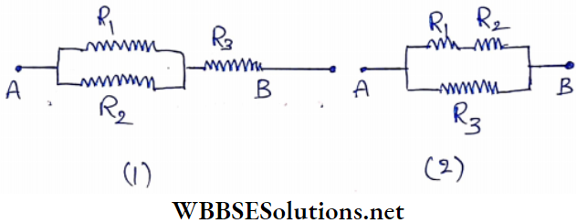
In this case also, by changing the relative positions of R1 and R3 and again of R2 and R3, two more similar mixed combinations are obtained. Equivalent resistance will change accordingly.
Connection Of Electric Cell In A Circuit Internal Resistance Of A Cell And Lost Volt
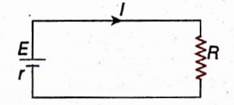
An arrangement in which a resistance R is joined between points A and B of a conducting wire that terminates at the two poles of a cell of emf E.
The resistance of the connecting wire is negligible. A current passes through R and completes the circuit from the negative pole to the positive pole inside the cell.
When the current flows through the cell the elements of the cell oppose it to some extent indicating that inside the cell a resistance is developed. This is the internal resistance of the cell (r).
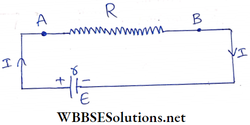
The equivalent resistance of the circuit = external resistance + internal resistance of the cell = R +r.
Current, \(I=\frac{E}{R+r} \quad \text { or, } E=I R+I r\)
Now, the potential difference of the external circuit i.e., the potential difference across the resistance, R is V = IR.
∴ E = V + Ir
or, V = E – Ir …(1)
V is the potential difference of the cell. Obviously, the value of V is less than E.
It indicates that the whole emf of the cell is not obtained as a potential difference in the external circuit.
A potential of magnitude Ir is lost inside the cell for the internal resistance (r).
This is called an internal potential drop or lost volt of the cell. This is so called because this portion of the emf of the cell does not contribute to the current through the external resistance.
Discussion:
Connection Of voltmeter: If the two ends of a voltmeter are connected to the two poles of a cell, the reading it indicates is not the value of E (emf of the cell) but the value of V (potential difference of the cell) because the voltmeter acts here as the external circuit.
Negligible internal resistance: if the internal resistance of the cell is very small in comparison to the external resistance then r may be taken as zero. Then Ir = 0 and no potential is lost inside the cell. So, emf of the cell and potential differences are equal.
For Example: In a lead-acid accumulator the magnitude of the internal resistance ranges from 0.01 fl to 0.1 fl. So, this resistance may be neglected in most of the electrical circuits.
Definition of electromotive force:
In an open circuit, no current flows in the external circuit i.e., 1=0. Then lost volt, Ir = 0 and V = E. From this relation emf of the tire cell may be defined as follows.
The potential difference between the two poles of a cell In an open circuit (when it does not deliver current in an external circuit) is called the emf of the cell.
Limit of current: In the equation V = E-Ir if the magnitude of l or r is very high then the magnitude of V becomes very small.IfIr becomes equal to E, then V = 0.
Thus the cell cannot produce any potential difference in the external circuit. So, for every cell has a maximum limit.
For Example, the emf of a dry cell is 1.5 V and if its internal resistance is 3Ω, the maximum current it delivers in the external circuit is \(I=\frac{E}{r}=\frac{1.5}{3}=0.5 \mathrm{~A}\). Hence primary cells are not used where high currents are required.
Voltage source and current source: Consider a battery of emf E with an internal resistance r, to which a variable resistor (R) is connected. The current in the circuit will be
⇒ \(I=\frac{E}{R+r}\)….(1)
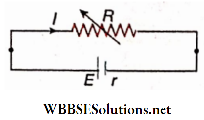
The potential differences between the two poles of the battery i.e., the term potential differences of the resistance R is
⇒ \(V^{\prime}=I R=\frac{E R}{R+r}\)….(2)
1. When r << R; we get from equation (2) \(V=\frac{E}{1+\frac{r}{R}} \approx E=\text { constant }\) Hence, whatever be the value of R, we get a constant potential difference (or voltage) from the battery. Under this condition, the battery is taken as a voltage source. 2. When r >> R, we get from equation (1),
⇒ \(I=\frac{E}{r\left(1+\frac{R}{r}\right)} \approx \frac{E}{r}=\text { constant }\)
Therefore, whatever the value of R, we get a constant current in the external circuit Under this, condition, the battery acts as a current source.
Understanding Ohm’s Law for Students
Connection Of Electric Cell In A Circuit Internal Resistance Of A Cell And Lost Volt Numerical Examples
Example 1. A resistor is fabricated by connecting two wires of the same material. The radii of the two wires are 1 mm and 3 mm respectively and their lengths are 3 cm and 5 cm respectively. If the two ends of the resistor are connected to the two terminals of a battery of emf 16 V and of negligible internal resistance, what will be the potential difference between the two ends of the wire of shorter length?
Solution:
Resistance of wire, \(R=\rho \frac{l}{A}=\rho \cdot \frac{l}{\pi r^2}\)
So, for the two wires of the same material,
⇒ \(\frac{R_1}{R_2}=\frac{l_1}{l_2} \times \frac{r_2^2}{r_1^2}\)
= \(\frac{3}{5} \times\left(\frac{3}{1}\right)^2\)
= \(\frac{27}{5}\)
The two wires are connected in series. So, the ratio of the potential difference across their ends is
⇒ \(\frac{V_1}{V_2}=\frac{I R_1}{I R_2}\)
= \(\frac{R_1}{R_2}=\frac{27}{5}\)
or, \(\frac{V_1}{V_1+V_2}=\frac{27}{27+5}\)
= \(\frac{27}{32}\)
or, \(V_1=\frac{27}{32}\left(V_1+V_2\right)\)
In the circuit, there are only two resistances. So the electromotive force,
⇒ ⇒\(E=V_1+V_2=16 \quad ∴ V_1=\frac{27}{32} \times 16=13.5 \mathrm{~V}\)
So, the potential difference across the resistance of length 3 cm
V1 = 13.5 V
Example 2. A heater of resistance 140Ω capable of carrying a current of 1.2 A Rasputin a dc mains of 210 V. Find out the minimum value of an additional resistance to be added to run the heater
Solution:
Let the value of the minimum additional resistance to be added be x Ω
We know, that V = IR
or, 210 = 1.2(140 + x) [Here R = 140 + x]
or, 140 + x = \(\frac{210}{1.2}\)
or, x = 175-140
or, x = 35Ω
So, a minimum additional resistance of 35Ω is to be added to run the heater
Example 3. To the parallel combination of two resistances 3Ω and 1Ω, a series combination of resistances 2.15Ω and 1Ω and a battery are connected. The internal resistance of the battery is 0.1Ω and the emf is 2 V. Determine the values of currents flowing through the resistances. Draw the diagram of the circuit
Solution:
The equivalent resistance of the parallel combination of 3Ω and 1Ω is
⇒ \(R=\frac{3 \times 1}{3+1}=\frac{3}{4}=0.75 \Omega\)
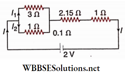
This equivalent resistance is in series with the other resistances.
So, the main current of the circuit is
⇒ \(I=\frac{2}{0.75+2.15+1+0.1}=\frac{2}{4}=0.5 \mathrm{~A}\)
This main current flows through the resistances 2.15Ω and 1Ω connected in series.
Now, current through 3Ω
⇒ \(I_1=I \times \frac{1}{3+1}=0.5 \times \frac{1}{4}=0.125 \mathrm{~A}\)
and current through 1Ω,
I2 = I – I1
= 0.5 – 0.125
= 0.375 A
Example 4. The electromotive force of a cell is 2 V. The potential difference becomes 1.5 V when a resistance of 15Ω is added to the two ends of the cell. Determine the internal resistance of the cell and the lost volt
Solution:
Lost volt = E – V
= 2-1.5
= 0.5 V
The current of the external circuit
⇒ \(=\frac{\text { potential difference of the external circuit }}{\text { resistance of the external circuit }}\)
⇒ \(\frac{1.5}{15}=0.1 \mathrm{~A}\)
This is the current flowing through the cell.
So, the internal resistance of the cell,
⇒ \(r=\frac{\text { lost volt }(I r)}{\text { current }(I)}=\frac{0.5}{0.1}=5 \Omega\)
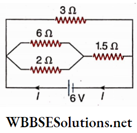
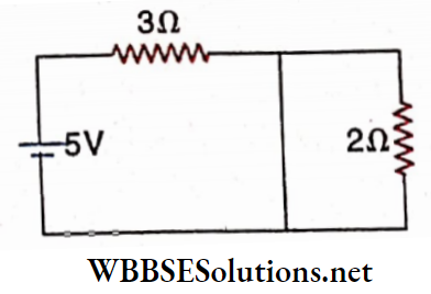
Example 5. In the given circuit diagram, what is the current sent by the battery?
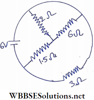
Solution:
The equivalent circuit.
The equivalent resistance of the middle branch
⇒ \(1.5+\frac{2 \times 6}{2+6}\)
= \(3 \Omega\)
With this 3Ω resistance, the outer 3Ω resistance on the right side is in parallel combination. So the equivalent resistance of the circuit
⇒ \(\frac{3 \times 3}{3+3}=\frac{3}{2} \Omega\)
∴ The main current of the circuit,
⇒ \(I=\frac{6}{\frac{3}{2}}=4 \mathrm{~A}\)
Comparison of Electromotive Force and Potential Difference:
In a source of electricity, chemical or some other form of energy is converted into electrical energy. This produces the electromotive force. Again when a source of electricity is connected to an external circuit, then a potential difference is developed at the two ends of the circuit. As a result, the electrical energy of the source is converted into another form of energy in the external circuit.
1. Due to the existence of electromotive force in the source of electricity, potential difference develops in the external circuit i.e., if the electromotive force is called the cause the potential difference may be called the ‘effect’.
2. The unit of electromotive force and potential difference is the same and this unit is volt.
3. An amount of potential is lost inside the source of electricity due to its internal resistance. So, the entire electromotive force cannot be obtained as the potential difference in the external circuit i.e., potential difference can never be greater than the electromotive force.
4. When the source of electricity does not send current in the external circuit i.e., when the circuit is open, then no potential is lost due to the internal resistance of the source. In that case, the potential difference between the two ends of the source becomes equal to its electromotive force.
5. The electromotive force of an electric cell without any defect is a constant quantity. But from the equation V = E-Ir it can be said that if the current flowing through the circuit increases or decreases, the potential difference at the two ends of the circuit decreases or increases accordingly.
Electric Current and Ohm’s Law Conclusion
- The amount of electric charge flowing through any cross-section of a conductor per second is called electric current strength.
- Coulomb = ampere x second (coulomb—a unit of electric charge, ampere—a unit of electric strength)
- In the external circuit electric current flows from the higher potential to the lower potential. In the internal circuit electric current flows from the lower potential to the higher potential.
- During electric discharge for a long time, the electromotive force of a lead-acid accumulator remains at 2.0 V.
- The total amount of charge that a secondary cell delivers to the external circuit while being discharged from the initial fully charged condition to the Anal fully discharged condition is called the capacity of that cell.
- The unit of capacity of an accumulator is ampere-hour (Ah).
- Energy efficiency of a cell or watt-hour efficiency
\(\eta=\frac{\text { average emf during discharging }}{\text { average emf during charging }}\) x ampere-hour efficiency
Electric Current and Resistance Notes WBCHSE
Ohm’s law: If temperature and other physical conditions remain the same, then die electric current flowing through a conductor is directly proportional to the potential difference between the two ends of the conductor.
- The property by virtue of which a conductor opposes the flow of current through it is called the resistance of the conductor.
- The electrical resistance of a conductor of unit cross-sectional area and unit length is defined as the resistivity of the material of the conductor,
- If the two electrodes of a source of electricity are connected with a conducting wire having almost no resistance, then the thus obtained is known as a short circuit.
- With the increase in temperature, the resistance of metals generally increases but that of electrolytes, carbon, glass, gas at low pressure, and semiconductors decreases.
- If a single resistance can replace a combination of resistances so that the circuit current and the terminal potential difference remain the same then that single resistance is called the equivalent resistance of that combination.
- In the case of a series combination of resistances, the value of the equivalent resistance is always greater than each of the component resistances.
- In the case of a parallel combination of resistances, the value of the equivalent resistance is always less than each of the component resistances.
- The entire electromotive force of a cell is not obtained as the potential difference in the external circuit. Due to the internal resistance of the cell some potential is used up by the interior of the cell. This is known as the internal potential drop or lost volt.
- The potential difference across the two electrodes of a cell in an open circuit is called the electromotive force of a cell.
- An ammeter is a current measuring device connected in series with the circuit and has very low resistance.
- A voltmeter is a potential-difference measuring device connected in parallel with the circuit and has very high resistance.
- In the case of the series combination of a number of cells: When the resistance of the external circuit is very much greater than the total internal resistance of the cells, then for n number of cells in series, the current Is n times that when a single cell is used.
- In the case of the parallel combination of a number of cells: When the resistance of the external circuit is 4 much less than the total Internal resistance of the cells,- then for n number of cells in parallel, the current is n times of that when a single cell is used.
In the case of a mixed combination of a number of cells:
- To get maximum current through the external circuit the cells should be arranged in series as well as in parallel in such a way that the equivalent resistance of the internal resistances of the cells becomes equal to the external resistance.
- During the passage of electric current through a metallic conductor, the average velocity with which the free electrons move through the conductor is known as the drift velocity of the free electrons.
- The amount of electric current flowing through the unit cross-sectional area of the conductor is called the current dencity through the conductor.
- The velocity with which an electric field propagates through a conductor is called the velocity of electric current.
- The mobility (μ) of a free electricity conductor is defined as the value of the drift velocity developed in it when the applied electric field is unit v
- V = IR
- [where, V= potential difference between the two ends of the conductor, I = electric current strength through any cross-section of the conductor, R = resistance]
- \(R=\rho \frac{l}{A}\)
- [p = specific resistance, l = length of the conductor, A = area of cross section of the conductor]
- Rt = R0(l + aaat)
- [R0 = resistance of the conductor at 0°C, Rt = resistance of the conductor at t°C, a = temperature coefficient of resistance, t = change in temperature]
The formula for the determination of equivalent resistance in series combination:
\(R=R_1+R_2+R_3+\cdots+R_n=\sum_{i=1}^n R_i\)The formula for the determination of equivalent resistance In parallel combination:
\(\frac{1}{R}=\frac{1}{R_1}+\frac{1}{R_2}+\frac{1}{R_3}+\cdots+\frac{1}{R_n}=\sum_{i=1}^n \frac{1}{R_i}\)- E = Ir+V
- [E = emf of the cell,I = current strength, r = internal resistance of the cell, V= potential difference]
- \(\frac{I_G}{I_S}=\frac{S}{G}\)
- [IG = current through the galvanometer, S = resistance of the shunt; Is current through the shunt, G = resistance of the galvanometer]
- \(S=\frac{G}{n-1}[n=\text { power of the shunt }]\)
- Current through the external resistance for a circuit containing n number of cells in series,
- \(I=\frac{n e}{R+n r}\)
- Current through the external resistance for a circuit containing n number of cells in parallel,
- \(I=\frac{n e}{n R+r}\)
- [e = emfof each cell, R = resistance ofexternal circuit, r = internal resistance of each cell]
- The condition for maximum current in the circuit for a mixed combination of cells is mR = nr.
- [where, m = number of rows connected in parallel combination, n =numberofcellsin eachrowconnectedIn series.]
- Drift velocity of free electrons
- \(v_d=\frac{I}{n e A}\)
- [where I = current strength, n – number of free electrons in unit volume, e = charge of each electron, A – area of cross-section of the conductor]
- Current density, \(j=\frac{I}{A}=n e v_d\)
- If Rs and Rp, respectively be the equivalent resistances of n number of resistances connected in series and parallel then
- \(\frac{R_s}{R_p}=n^2\)
- If a wire of resistance R is divided into n number of equal parts and they are connected in parallel, then the equivalent resistance of the combination will be \(\frac{R}{n^2}[/ltaex]
- If equivalent r∈ sistance of R1 and R2 in series and parallel be Rs and Rp respectively, then
- [latex]R_1=\frac{1}{2}\left[R_s+\sqrt{R_s^2-4 R_s R_p}\right]\)
- \(R_2= \frac{1}{2}\left[R_s-\sqrt{R_s^2-4 R_s R_p}\right]\)
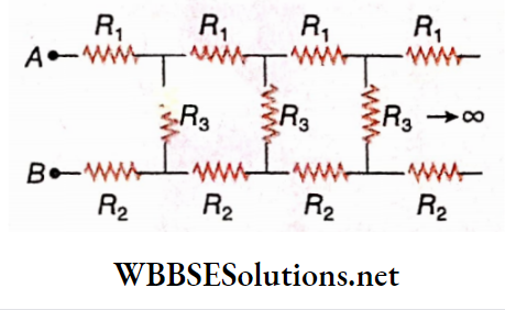
- In the given diagram, the equivalent resistance between the points A and B is
- \(R_{A B}=\frac{1}{2}\left(R_1+R_2\right)+\frac{1}{2}\left[\left(R_1+R_2\right)^2+4 R_3\left(R_1+R_2\right)\right]^{\frac{1}{2}}\)
- If n number of identical cells are connected in a loop in order, then the terminal potential difference of any one cell is zero.
- In a parallel combination of two resistances, the current gets divided into two branches.
- Branch current = main current x \(\frac{\text { resistance of other branch }}{\text { sum of the two resistances }}\)
- n cells each of emf E and internal resistance r are connected in series and by mistake, m cells are wrongly connected.If this series combination of cells is connected to an external resistance R, then
- Effective emf of the combination, E’ = (n-2m)E,
- Total internal resistance = nr
- The total resistance of the circuit = nr+ R
- Current through the circuit, \(I=\frac{(n-2 m) E}{n r+R}\)
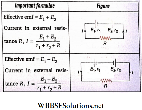
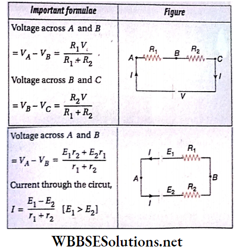
- If two cells of emf Ej and E2 and internal resistances Tj and r2 respectively are connected in parallel to an external resistance R, then
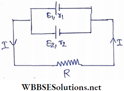
- Effective emf = \(\frac{E_1 r_2+E_2 r_1}{r_1+r_2}\)
- Effective internal resistance = \(\frac{r_1 r_2}{r_1+r_2}\)
- Current through the circuit, \(I=\frac{E_1 r_2+E_2 r_1}{r_1 r_2+R\left(r_1+r_2\right)}\)
- Percentage change in resistance due to change in size of wire:
- \(\frac{\Delta R}{R} \times 100 \%=2 \frac{\Delta l}{l} \times 100 \%\)
- \(\frac{\Delta R}{R} \times 100 \%=-2 \frac{\Delta A}{A} \times 100 \%\)
- \(\frac{\Delta R}{R} \times 100 \%=-4 \frac{\Delta r}{r} \times 100 \%\)
- [where l = length of the conductor, r = radius of the conductor and A = cross-sectional area of the conductor.]
- \(\frac{R_1}{R_2}=\frac{l_1 A_2}{l_2 A_1}=\frac{l_1 \pi r_2^2}{l_2 \pi r_1^2}=\frac{l_1 r_2^2}{l_2 r_1^2} \text { and } \frac{A_1}{A_2}=\frac{l_2}{l_1}\)
- When different cells are connected in different patterns:
Ohm’s Law Very Short Questions And Answers
Question 1. For what property of conductors, current will flow through a wire connecting them?
Answer: Potential Difference
Question 2. Does the emf of a standard electric cell depend on the volume of the cell?
Answer: No
Question 3. What kind of cell should be preferred to get a high current?
Answer: Secondary cell
Question 4. Which active electrolyte is used in a lead-acid accumulator
Answer: Sulphuric acid
Question 5. If a current of 1 mA flows through a conductor having a potential difference of 1 V between its two ends, what will be the resistance of the conductor?
Answer: 1000Ω
Question 6. For a metallic conductor, what is the nature of the graph of current strength vs. potential difference?
Answer: Straight line
Question 7. The resistance of a conductor is 200Ω and the current through it is 10 mA. What is the potential difference across the two ends of the conductor?
Answer: 2V
Question 8. The resistivity of copper is 1.76 x 10⁻⁶ Ω. cm. Express it in
Answer: 1.76 x 10⁻⁸Ω.m
Question 9. The resistivity of copper is 1.76 x 10⁻⁶Ω.cm. Determine the resistance of a copper rod having a length of 10 cm and cross
Answer: 1.76 x 10⁻⁵.Ω
Question 10. Two conducting wires of lengths l and 2l have the same cross-sectional area. Compare their resistances.
Answer: Ratio = 1:2
Question 11. Two wires A and B are of the same metal and of the same length. Their areas of cross section are in the ratio of 2: 1. If the same potential difference is applied across each wire in turn, what will be the ratio of the currents flowing in A and B?
Answer: 2: 1
Question 12. What will be the change in the resistance of a Eureka wire, when its radius is halved and length is reduced to one-fourth of its original length?
Answer: Resistance Is Unchanged
Question 13. Two wires A and B of the same metal have the same cross-sectional area and have their lengths in the ratio 2:1. What will be the ratio of currents flowing through them respectively, when the same potential difference is applied across each of them?
Answer: 2:1
Question 14. Name a substance whose resistance decreases with the
Answer: Semiconductor
Question 15. What is the unit of temperature coefficient of resistance?
Answer: ºC-1
Question 16. The temperature coefficient of resistance for the material of a conductor is 38 x 10-4 ºC-1. What will be its value in ºF-1? The range of rise in temperature can be assumed small.
Answer: 21.1 x 10⁻⁴ºF-1
Question 17. A carbon resistor is coloured with four different bands brown, black, orange, and silver respectively. Find the range of its probable resistance.
Answer: 9000-11000Ω
Question 18. The resistance of a carbon resistor is 6.8kfl. What is the first
Answer: Blue, Grey, Red
Question 19. Of metals and alloys, which has a greater value of temperature coefficient of resistance?
Answer: Metals
Question 20. How are different electrical appliances connected in domestic electric connection?
Answer: In parallel
Question 21. Two resistances 1Ω and 2Ω are connected in series and a potential difference of 6Ω is applied across the ends of this combination. What will be the terminal potential difference across the second resistance?
Answer: 4V
Question 22. Two resistances 1Ω and 2Ω are connected in parallel and a potential difference of 6 V is applied across the ends of this combination. Calculate the current through the second conductor.
Answer: 3A
Question 23. In the circuit given, what is the potential difference between the two points A and B?
Answer: 6V
Question 24. What is the value of I in the circuit?
Answer: 3A
Question 25. Two resistances of 6Ω and 3Ω are connected in parallel. When current is sent through this combination, compare the currents through the resistances.
Answer: Ratio = 1:2
Question 26. A metallic wire of resistance R is folded into two equal parts and then wound well. What will be new resistance then?
Answer: \(\frac{R}{4}\)
Question 27. The resistance of an electrical appliance is 200Ω and it can withstand a maximum current of 1 A. To operate the appliance on a dc source of 220 V what minimum resistance should be connected in series with it?
Answer: 20Ω
Question 28. The equivalent resistance of two resistances in a series is four times the equivalent resistance when they are in parallel. If one of the resistances is R, then what would be the resistance of the other?
Answer: R
Question 29. Three resistances, each of 4Ω, are connected in the form of an equilateral triangle. Find the effective resistance between its two corners.
Answer: 2.67Ω
Question 30. Name the quantity for which the potential difference of a cell becomes less than its emf due to its internal resistance.
Answer: Lost Volt
Question 31. Emf of a cell is 1.5 V and its internal resistance is 1Ω. When the cell sends current in an external circuit having resistance 2Ω, then what will be the value of the lost volt?
Answer: 0.5 V
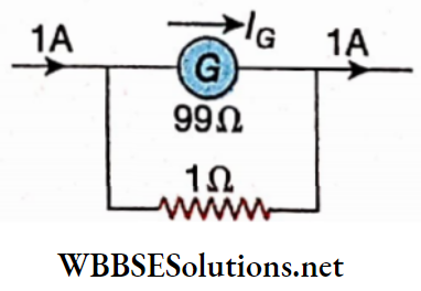
Question 32. When a shunt of 1Ω is connected in parallel with a galvanometer, 1% of the main current flows through the galvanometer. Determine the resistance of the galvanometer.
Answer: 99Ω
Question 33. If the current through a galvanometer of resistance G is to be reduced n times, what should be the shunt resistance?
Answer: \(\frac{G}{n-1}\)
Question 34. A shunt of 1Ω is connected in parallel with a galvanometer of resistance 99Ω. If the main current of the circuit be 1 A, then what will be the galvanometer current?
Answer: 0.01 A
Question 35. n electric cells having emf e and internal resistance r each are connected in parallel. What is the emf of this combination?
Answer: e
Question 36. n electric cells of emf e and internal resistance r each are connected in series. What is the emf of this combination?
Answer: ne
Question 37. The potential difference across a given copper wire is increased. What happens to the drift velocity of the charge carriers?
Answer: It Increases
Ohm’s Law Fill in The Blanks
Question 1. Lead oxide is used as a positive electrode in a lead-acid accumulator as an active component
Question 2. Spongy lead is used as a negative electrode in a lead-acid accumulator as an active component
Question 3. The internal resistance of a secondary cell is less than that of a primary cell
Question 4. Equivalent resistance in a parallel combination is less than each of the component resistances
Question 5. If the current through a circuit or the internal resistance of a cell is zero, then the value of the lost volt becomes zero
Question 6. In metallic conductor, the direction of conventional current is opposite to the direction of the flow of free electrons
Question 7. The velocity of electric current is much greater than the drift velocity of free electrons in a metallic conductor
Ohm’s Law Assertion Reason Type
Direction: These questions have Statement 1 and Statement n. Of the four choices given below, choose the one that best describes the two statements.
- Statement 1 is true, Statement 2 is true; Statement 2 is a correct explanation for Statement 1.
- Statement 1 is true, Statement 2 is true; Statement 2 is not a correct explanation for Statement 1.
- Statement 1 is true, Statement 2 is false.
- Statement 1 is false, and Statement 2 is true.
Question 1.
Statement 1: If a conducting wire is stretched to twice its length, the resistance becomes twice.
Statement 2: For a fixed wire, the resistance is proportional to its length.
Answer: 4. Statement 1 is false, Statement 2 is true.
Question 2.
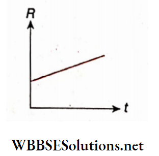
Statement 1: The temperature (t) dependence of the resistance (R) of a metallic conductor.
Ohm’s Law Formulas and Applications WBCHSE
Statement 2: The resistance R of a metallic conductor is related to its temperature t as R = R0(1 + αt).
Answer: 1. Statement 1 is true, Statement 2 is true; Statement 2 is a correct explanation for Statement 1.
Question 3.
Statement 1: The drift velocity of free electrons is vd when a current passes through a copper wire. The drift velocity is halved when the same current passes through another copper wire of double the diameter.
Statement 2: For the same current, the drift velocity of free electrons in a metal wire is inversely proportional to the area of the cross-section of the wire.
Answer: 4. Statement 1 is false, Statement 2 is true.
Question 4.
Statement 1: In the circuit of no current passes through the 2Ω resistor.
Statement 2: The current through a resistor is proportional to its terminal potential difference.
Answer: 1. Statement 1 is true, Statement 2 is true, and Statement 2 is a correct explanation for Statement 1.
Question 5.
Statement 1: In the circuit of IG = 10 mA.
Statement 2: If a shunt of resistance \(\frac{G}{n}\) is connected parallel to a galvanometer, \(\frac{1}{n}\) times the main circuit current passes through the galvanometer.
Answer: 3. Statement 1 is true, Statement 2 is false.
Question 6.
Statement 1: The voltmeter reading does not denote the correct emf of an electric cell when the terminals of the cell are directly connected to the voltmeter.
Statement 2: As every electric cell has some internal resistance, the current in the external circuit is reduced to some extent.
Answer: 2. Statement 1 is true, Statement 2 is true; Statement 2 is not a correct explanation for Statement 1.
Question 7.
Statement 1: In the circuit of the internal potential drop of the cell decreases with the increase of the external resistance R
Statement 2: The potential difference available from an electric cell in the external circuit is proportional to the resistance of that external circuit.
Answer: 3. Statement 1 is true, Statement 2 is false.
Question 8.
Statement 1: If a current flows through a wire of a non-uniform cross-section, the potential difference per unit length of the wire in the direction of the current is the same at different points.
Statement 2: V = IR and the current in the wire is the same throughout.
Answer: 4. Statement 1 is false, Statement 2 is true.
Question 9.
Statement 1: Out of the galvanometer, ammeter, and voltmeter, the resistance of the ammeter is the lowest and the resistance of the voltmeter is the highest.
Statement 2: An ammeter is connected in series and a voltmeter is connected in parallel, in a circuit.
Answer: 2. Statement 1 is true, Statement 2 is true; Statement 2 is not a correct explanation for Statement 1.
Question 10.
Statement 1: A current flows in a conductor only when there is an electric field within the conductor.
Statement 2: The drift velocity of electrons decreases in the presence of the electric field.
Answer: 3. Statement 1 is true, and Statement 2 is false.
Ohm’s Law Match The Columns
Question 1. Three uniform conducting wires of the same material have lengths in the ratio 2:2:1 and radii in the ratio 2:1:1. The resistance of the first wire is R.
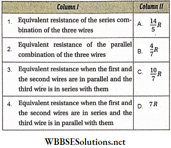
Answer: 1-D, 2-B, 3-A, 4-C
Question 2. Silver has the highest electrical conductivity among different metals. Some materials are given in Column A and their resistivities (in Ω.cm) are in Column B.
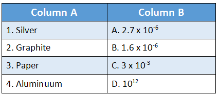
Answer: 1-B, 2-C, 3-D, 4-A
Question 3. Match the following two columns in the context of an electric current passing through a metal conductor.
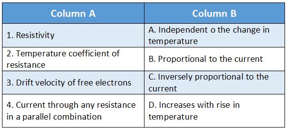
Answer: 1-D, 2-A, 3-B, 4-C
Question 4. In the circuit, the ammeter A and the voltmeter V are both ideal. Each of the cells E1 and E2 has an emf of 2 V and an internal resistance of 2Ω
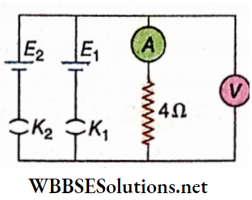
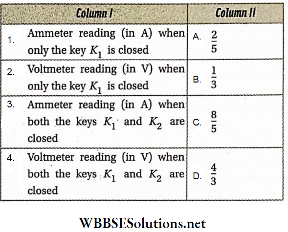
Answer: 1-B, 2-D, 3-A, 4-C
Question 5. In the circuit of the galvanometer resistance is G = 100Ω.
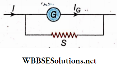
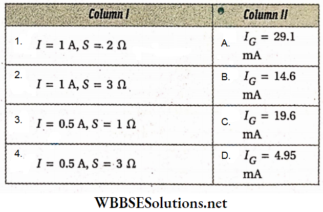
Answer: 1-C, 2-A, 3-D, 4-B
Question 6. The first three characteristic colors of carbon resistors are given in column A and their resistances in column B.
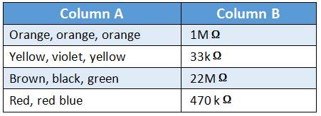
Answer: 1-B, 2-D, 3-A, 4-C
Question 7. Match the columns from the circuit.
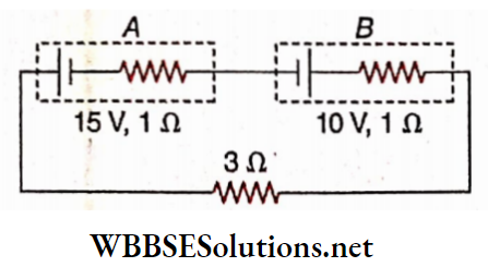
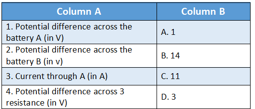
Answer: 1-B, 2-C, 3-A, 4-D