
Class 12 Physics Electromagnetic Induction And Alternating Current
Question 1. The 60pF capacitor is connected to a 110 V, 60 Hz ac supply. Determine the rms value of the current in the circuit. What is the net power absorbed by the circuit over a complete cycle?
Answer:
∴ \(I_{\mathrm{rms}}=\frac{V_{\mathrm{rms}}}{X_C}\)
Where, \(X_c=\frac{1}{2 \pi f C}=\frac{1}{2 \pi \times 60 \times 60 \times 10^{-6}} \Omega\)
and Vrms = 110V
Irms = 110(2π x 60 x 60 x 10-6)A = 2.49 A
The net power absorbed is zero as in the case of an ideal capacitor there is no power loss.
Question 2. Determine the resonant frequency ωr of a series LCR circuit with L = 2.0 H, C = 32 μF, and R = 10 Ω. What is the Q-value of this circuit?
Answer:
= \(\omega_r=\frac{1}{\sqrt{L C}}=\frac{1}{\sqrt{2 \times 32 \times 10^{-6}}}=125 \mathrm{~s}^{-1}\)
∴ \(Q=\frac{X_L}{R}=\frac{\omega_r L}{R}=\frac{125 \times 2}{10}=25\)
Read And Learn More WBCHSE Class 12 Physics Short Question And Answers
Question 3. A charged 30 μF capacitor is connected to a 27 mH inductor.
- What is the angular frequency of free oscillations of the circuit?
- If the initial charge on the capacitor is 6 mC then what is the total energy stored in the circuit initially? What is the total energy at a later time?
Answer:
- \(\omega_r=\frac{1}{\sqrt{L C}}=\frac{1}{\sqrt{27 \times 10^{-3} \times 32 \times 10^{-6}}}=1.1 \times 10^3 \mathrm{~s}^{-1}\)
- \(E=\frac{1}{2} \frac{Q^2}{C}=\frac{1}{2} \frac{\left(6 \times 10^{-3}\right)^2}{30 \times 10^{-6}}=0.6 \mathrm{~J}\)
There will be no change in total energy.
Question 4. A series LCR circuit with R = 20 Ω, L = 1.5 H, and C = 35 μF F is connected to a variable frequency 200 V ac supply. When the frequency of the supply equals the natural frequency of the circuit, what is the average power transferred to the circuit in one complete cycle?
Answer:
When natural frequency and supply frequency are equal, resonance occurs.
∴XL = XC ∴Z = R
P = \(\frac{V^2}{Z}=\frac{V^2}{R}=\frac{200 \times 200}{20}=2000 \mathrm{~W}\)
WBBSE Class 12 Alternating Current Short Answer Questions
Question 5. A radio can tune over the frequency range of a portion of the MW broadcast band: 800 kHz to 1200 kHz. If its LC circuit has an effective inductance of 200μH, what must be the range of the variable capacitor?
[Hint: for tuning, the natural frequency of the LC circuit should be equal to the frequency of the radio wave.]
Answer:
∴ \(f=\frac{1}{2 \pi \sqrt{L C}} \quad \text { or, } C=\frac{1}{4 \pi^2 f^2 L}\)
when L = 200 μH and f = 800 kHz,
∴ \(C_1=\frac{1}{4 \pi^2 \times 800 \times 800 \times 10^6 \times 200 \times 10^{-6}}\)
= 87.9 pF
when f = 1200 kHz,
∴ \(C_2=\frac{1}{4 \pi^2 \times 1200 \times 1200 \times 10^6 \times 200 \times 10^{-6}}\)
= 87.9 pF
The range of the capacitance should be between 87.9 pF and 197.8 pF, i.e., between 88 pF and 198 pF.
Question 6. A series LCR circuit is connected to a variable frequency 230 V source. L = 5.0 H, C = 80μF, R = 40Ω.
- Determine the source frequency for which resonance occurs in the circuit.
- Obtain the impedance of the circuit and amplitude of current at resonance.
- Determine the rms potential drop across L and C.
- Show that at resonance the potential drop across LC combination is zero.
Answer:
1. \(\omega_r=\frac{1}{\sqrt{L C}}=\frac{1}{\sqrt{5 \times 180 \times 10^{-6}}}=50 \mathrm{rad} \cdot \mathrm{s}^{-1}\)
2. At resonance impedance, Z = R = 40 H
∴ \(I_{\max }=\frac{V_{\max }}{R}=\frac{\sqrt{2} \times 230}{40}=8.1 \mathrm{~A}\)
3. Across L, VL = I x XL = IωL
∴ VL = 8.1 x 50 x 5 = 2025 V
Across \(C, V_C=\frac{I}{\omega C}=\frac{8.1}{50 \times 80 \times 10^{-6}}=2025 \mathrm{~V}\)
The potential drop across LC combination = VL – VC = 0.
Question 7. An LC circuit has L = 20 mH, C = 50μF and initial. charge 10 mC the resistance being negligible.
- What is the total energy stored initially? Is it conserved during the LC oscillator?
- What is the natural frequency of the circuit?
- After what time interval from the moment the circuit is switched on the energy stored is
- Completely electrical i.e., stored only in the capacitor and
- Completely magnetic, i.e., stored only in the inductor?
- At what time is the total energy shared equally between the inductor and the capacitor?
- If a resistor is inserted in the circuit, how much energy is dissipated as heat?
Answer:
1. Total Initial energy = \(\frac{1}{2} \frac{Q^2}{C}=\frac{1}{2} \frac{10^{-4}}{50 \times 10^{-6}}=1 \mathrm{~J}\)
If R = 0, then total energy is conserved.
2. \(\omega=\frac{1}{\sqrt{L C}}\)
∴ Resonance frequency,
⇒ \(\omega=\frac{1}{\sqrt{20 \times 10^{-3} \times 50 \times 10^{-6}}}=10^3 \mathrm{rad} \cdot \mathrm{s}^{-1}\)
⇒ \(f=\frac{\omega}{2 \pi}=\frac{10^3}{2 \times 3.14}=159 \mathrm{~Hz}\)
3. q = q0 cos ωt
1. When \(t=0, \frac{T}{2}, T, \frac{3 T}{2}, \ldots \ldots\)
then q = ±q0 i.e., the energy is completely electrical.
2. When \(t=\frac{T}{4}, \frac{3 T}{4}, \frac{5 T}{4}, \ldots \ldots\)
then q = 0 i.e., the energy is purely magnetic.
4. \(E=\frac{q^2}{2 C}=\frac{1}{2 C} q_0^2 \cos ^2 \omega t\)
when ωt = 45°, \(\cos \omega t=\frac{1}{\sqrt{2}}\)
∴ \(E=\frac{1}{2 C} \cdot q_0^2 \cdot \frac{1}{2}=\frac{1}{2}\left(\frac{q_0^2}{2 C}\right)=\frac{1}{2}\) x total energy
so, when \(\omega t=45^{\circ} \text { or } t=\frac{T}{8}, \frac{3 T}{8}, \frac{5 T}{8}, \cdots\) the energy is shared equally between the capacitor and inductor.
5. When a resistor is connected in the circuit, all the energy stored in the circuit (i.e., 1 J ) will be dissipated as heat energy since the LC oscillation will be damped and stop ultimately.
Real-Life Applications of AC and DC Currents
Question 8. A coil of inductance 0.50 H and resistance 100 Ω is connected to a 240 V, 50 Hz AC supply.
- What is the maximum current in the coil?
- What is the time lag between the voltage maximum and current maximum?
- If the circuit is connected to a high-frequency supply (240 V, 10 kHz ), what will be the answer to (1) and (2). From the answer explain the statement that at a very high frequency the presence of a inductor in the circuit nearly amounts to an open circuit.
- How does an inductor behave in a dc circuit after the steady state?
Answer:
1. \(I_{\max }=\frac{V_{\max }}{\sqrt{R^2+\omega^2 L^2}}=\frac{\sqrt{2} \times 240}{\sqrt{100^2+(2 \pi \times 50 \times 0.5)^2}}\)
= 1.82A
2. \(\tan \phi=\frac{X_L}{R}=\frac{2 \pi f L}{R}=\frac{2 \pi \times 50 \times 0.5}{100}=1.571\)
∴ Φ = tan-11.571 = 57.5°
∴ Time interval = \(\frac{T}{360} \times \phi=\frac{\phi}{360 f}\)
= \(\frac{57.5}{360 \times 50}=3.19 \times 10^{-3} \mathrm{~s}\)
3. ω = 2πf = 2π x 104 rad s-1.
∴ \(I_{\max }=\frac{V_{\max }}{\sqrt{R^2+\omega^2 L^2}}=\frac{240 \sqrt{2}}{\sqrt{100^2+4 \pi^2 \cdot 10^8 \cdot 5^2}}=0.011 \mathrm{~A}\)
∴ \(\phi=\tan ^{-1}\left\{\frac{X_L}{R}\right\}=\tan ^{-1}\left(\frac{2 \pi f L}{R}\right)\)
= \(\tan ^{-1} \frac{2 \pi \times 10^4 \times 0.5}{100}\)
= \(\tan ^{-1}(100 \pi) \approx \frac{\pi}{2}\)
∴ Time interval = \(\phi \cdot \frac{T}{360}=\frac{\phi}{360 f}\)
= \(\frac{90}{360 \times 10 \times 10^3}=0.25 \times 10^{-4} \mathrm{~s}\)
Imax is very small. So it can be concluded that at high frequencies an inductance behaves as an open circuit.
4. In a steady dc circuit, f = 0.
The inductance acts as a simple conductor.
Question 9. A circuit containing an 80 mH inductor and a 60μF capacitor in series is connected to a 230 V, 50 Hz supply. The resistance of the circuit is negligible.
- Obtain the current amplitude and rms values.
- Obtain rms values of potential drops across the inductor and capacitor.
- What is the average power transferred to the inductor?
- What is the average power transferred to the capacitor?
- What is the total average power absorbed by the circuit?
Answer:
1. \(I_{\max }=\frac{V_{\max }}{\sqrt{R^2+\left(X_L-X_C\right)^2}}\)
∴ XL = ωL = 100π x 80 x 10-3 = 25.12 Ω
∴ \(X_C=\frac{1}{\omega C}=\frac{1}{100 \pi \times 60 \times 10^{-6}}=53.03 \Omega\)
∴ \(I_{\max }=\frac{230 \sqrt{2}}{\sqrt{(25.12-53.03)^2}}=11.6 \mathrm{~A}\)
= \(I_{\mathrm{rms}}=\frac{I_{\max }}{\sqrt{2}}=\frac{11.6}{\sqrt{2}}=8.20 \mathrm{~A}\)
2. \(V_L=I_{\mathrm{rms}} \cdot \omega L=8.20 \times 25.12 \approx 206 \mathrm{~V}\)
∴ \(V_C=I_{\mathrm{rms}} \cdot \frac{1}{\omega C}=8.20 \times 53.03 \approx 435 \mathrm{~V}\)
3. Average power transferred to the inductor,
∴ \(P_L=V I \cos \phi=V I \cos \frac{\pi}{2}=0\)
4. Average power transferred to the capacitor,
∴ \(P_C=V I \cos \phi=V I \cos \frac{\pi}{2}=0\)
5. Average power absorbed by the circuit = 0
Question 10. A series LCR circuit with L = 0.12H, C = 480nF, and R = 23 Ω is connected to a 230 V variable frequency supply.
- What is the source frequency for which the current amplitude is maximum? Obtain this maximum value.
- What is the source frequency for which the average power absorbed by the circuit is maximum? Obtain the value of this maximum power.
- What is the Q-factor of the circuit?
Answer:
1. The current amplitude and average absorbed power both are maximum at the resonant frequency.
∴ \(f_0=\frac{1}{2 \pi \sqrt{L C}}=\frac{1}{2 \times 3.14 \sqrt{0.12 \times 480 \times 10^{-9}}}\)
= 663 Hz
The current amplitude is maximum when the source frequency is 663 Hz.
∴ \(I_{\max }=\frac{V_{\max }}{R}=\frac{230 \sqrt{2}}{23}=14.14 \mathrm{~A}\)
2. The average absorbed power is maximum when the source frequency is 663 Hz.
∴ \(P_{\mathrm{av}}=\frac{1}{2} I_{\max }^2 R=\frac{1}{2} \times(14.14)^2 \times 23=2300 \mathrm{~W}\)
3. \(Q=\frac{X_L}{R}=\frac{2 \pi f_0 \cdot L}{R}=\frac{2 \pi \times 663 \times 0.12}{23}=21.7\)
Common Questions on AC Power and Reactance
Question 11.
- In any ac circuit, is the applied instantaneous voltage equal to the algebraic sum of the instantaneous voltages across the series elements of the circuit?
- Is the same true for rms voltage?
Answer:
- Yes.
- No, it is not true for rms voltage because the potential differences across various parts of the circuit may not be in the same phase.
Question 12. Why a capacitor is used in the primary circuit of an induction coil?
Answer:
Whenever there is a break in the current, a large emf is induced in the circuit which is utilized in charging the capacitor. This prevents any spark in the circuit.
Question 13. When a choke is connected In series with a lamp in the DC line, the lamp shines brightly. The insertion of an Iron core in the choke does not affect the brightness. What happens In the case of ac line?
Answer:
An inductance acts as a simple conductor in a dc line, and reducing its self-inductance by introducing an iron core, does not affect the brightness of the lamp. In ac line the presence of inductance results in a drop of voltage. So the brightness of the lamp decreases. The introduction of the iron core further reduces the brightness of the lamp.
Question 14. Why a choke is needed with a fluorescent lamp with ac mains? Why a normal resistor cannot be used in place of the choke?
Answer:
An inductor can introduce a voltage drop in a circuit without any loss of power but a resistor gets heated during the process and some power is lost. A choke acts as an inductor in a circuit, so a choke is used in place of a resistor.
Question 15. A small town with a demand of 800 kW of power at 220 V is situated 15 km away from an electric plant generating power at 440 V. The resistance of the two-wire line carrying power is 0.5H.km-1. The line gets power from the line through a 4000-220 V step-down transformer at a substation in the town.
- Estimate the line power loss in the form of heat.
- How much power must the plant supply, assuming there is negligible power loss due to leakage?
- Characterize the step-up transformer at the plant.
Answer:
1. Total resistance of the line = 0.5 x 15 x 2 = 15 Ω rms current through the line,
∴ \(I_{\mathrm{rms}}=\frac{\text { power }}{\text { voltage }}=\frac{800 \times 1000}{4000}=200 \mathrm{~A}\)
∴ Power loss due to the generation of heat
= I2rms.R = (200)2 x 15 = 600 kW
2. Power supplied by the plant = 800 + 600 = 1400 kW
3. Voltage dropin the line
= Irms .R = 200 x 15 = 3000 V
∴ The plant transformer should supply (4000 + 3000) = 7000 V
∴ A 440 V/7000V step-up transformer should be used.
Question 16. An ac having a peak value of 1.41 ampere is used to heat a wire. A dc producing the same heating rate will be approximately.
- 1.41 A
- 2.0 A
- 0.705 A
- 1.0 A
Answer: 4. 1.0 A
The rms value of the alternating current,
∴ \(I_{\mathrm{rms}}=\frac{I_0}{\sqrt{2}}=\frac{1.41}{1.41}=1 \mathrm{~A}\)
Hence, the dc required to produce the same heating rate =1 A.
The option 4 is correct.
Question 17. An ac voltage e = E0 sin cot is applied across an ideal inductor of self-inductance [L]. Write down the peak current.
Answer:
Peak value of the current = \(\frac{E_0}{\omega L}\)[Inductive reactarpe = ωL]
Question 18. The instantaneous voltage from an ac source is given by e = 200 sin 314t volt. Find the rms voltage. What is the frequency of the source?
Answer:
Peak voltage = 200 V
Then, rms voltage = \(\frac{200}{\sqrt{2}}=141.4 \mathrm{~V}\)
Angular frequency, \(\omega=314 \mathrm{~Hz}\)
The frequency of the source = \(\frac{\omega}{2 \pi}=\frac{314}{2 \times 3.14}=50 \mathrm{~Hz}\)
Question 19. State the condition trader in which the phenomenon of resonance occurs in a series LCR circuit when ac voltage is applied. In a series LCR circuit, the current is in the same phase as the voltage. Calculate the value of self-inductance if the capacitor is 20 μF and the resistance used is 10 ohm with the ac source of frequency 50 Hz.
Answer:
Condition of resonance in a series LCR circuit:
∴ \(\omega L=\frac{1}{\omega C}\)
where a) = angular frequency of the source, L = self-inductance of the coil, and C = capacitance.
According to the question, electric current and emf are in the same phase in the LCR circuit, i.e., the circuit is in the resonance condition.
Here, ω = 2π x 50 = 2 x 3.14 x 50 = 314 Hz
C = 20 μF = 20 x 10-6 F = 2 x 10⁻⁵ F
Now, \(\omega L=\frac{1}{\omega C}\)
or, \(L=\frac{1}{\omega^2 C}=\frac{1}{(314)^2 \times\left(2 \times 10^{-5}\right)}=0.507 \mathrm{H}\)
Examples of Calculating RMS Values in AC Circuits
Question 20. Whatis Q-factor?
Answer:
Q-factor is a dimensionless parameter that describes how underdamped an oscillator or a resonator is.
Question 21.
- Compare between inductive reactance and capacitive reactance.
- In an LCR series combination, R = 400Ω, L = 100 mH and C= 1μF. This combination is connected to a 25 sin 2000t volt voltage source. Find the impedance of the circuit and the peak value of the circuit current.
Answer:
1. Inductive reactance, XL = coL increases with the increase of either frequency or inductance or both. Capacitive reactance, \(X_C=\frac{1}{\omega C}\) decreases with the increase of either frequency or capacitance or both.
2. 1st Part: Frequency of the source, ω = 200 rad/s
∴ Impedance,
∴ \(Z=\sqrt{R^2+\left(\omega L-\frac{1}{\omega C}\right)^2}\)
= \(\sqrt{400^2+\left(2000 \times 100 \times 10^{-3}-\frac{1}{200 \times 10^{-6}}\right)^2}\)
= \(\sqrt{16 \times 10^4+9 \times 10^4}=500 \Omega\)
2nd Part: Peak value of current,
∴ \(I_0=\frac{V_0}{R}=\frac{25}{400}=62.5 \mathrm{~mA}\)
Question 22.
- Why is the use of ac voltage preferred over dc voltage?
- The power factor of the LR circuit is \(\frac{1}{\sqrt{3}}\). If the frequency of ac is doubled, what will be the power factor?
Answer:
1. Ac voltage can be stepped up or stepped down using a transformer, which is essential for power transmission. and power consumption in daily life. In addition, any capacitor or inductor can be used as an active component in an ac circuit,.These advantages are not provided by dc voltages.
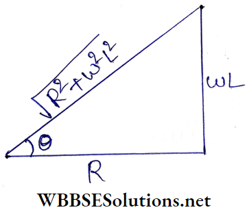
2. If the phase difference between the voltage and the current in the LR circuit is θ,
∴ \(\tan \theta=\frac{\omega L}{R}\)
From the figure, power factor,
∴ \(\cos \theta=\frac{R}{\sqrt{R^2+\omega^2 L^2}}\)
In the first case,
∴ \(\frac{R}{\sqrt{R^2+\omega^2 L^2}}=\frac{1}{\sqrt{3}} \quad \text { or, } \frac{R^2}{R^2+\omega^2 L^2}=\frac{1}{3}\)
or, ω2L2 = 3R2 – R2 = 2R2
In the second case, the frequency Is doubled. The new frequency Is 2ω.
∴ Power factor = \(\frac{R}{\sqrt{R^2+4 \omega^2 L^2}}=\frac{R}{\sqrt{R^2+4 \times 2 R^2}}\)
= \(\frac{R}{\sqrt{9 R^2}}=\frac{1}{3}\)
Question 23. If the rotating speed of a dynamo is doubled, the induced electromotive force will be
- Doubled
- Halved
- Four times as much
- Unchanged
Answer: 1. Doubled
e = ωBANsin(ωt + α); if w is doubled then e is also doubled.
The option 1 is correct.
Question 24. The number of turns of the primary and secondary of a transformer are 500 and 5000 respectively. The primary is connected to a 20 V, 50 Hz ac supply. The output of the secondary will be
- 2 V, 50 Hz
- 200 V, 50 Hz
- 200 V, 5 Hz
- 200 V, 500 Hz
Answer: 2. 200 V, 50 Hz
Output voltage = \(20 \times \frac{5000}{500}=200 \mathrm{~V}\); the frequency will not change.
The option 2 is correct.
Question 25. What is the rms value of the current i = 5√2 sin 100 t A?
Answer:
rms value = \(\frac{\text { peak value }}{\sqrt{2}}=\frac{5 \sqrt{2}}{\sqrt{2}}=5 \mathrm{~A}\)
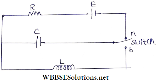
Question 26. In the circuit shown below, the switch Is kept In position a for n long time and is then thrown to position b. The amplitude of the resulting oscillating current Is given by
- \(B \sqrt{L / C}\)
- E/R
- Infinity
- \(E \sqrt{C / L}\)
Answer: 4. \(E \sqrt{C / L}\)
If the switch Is kept In position for a long time, the charge accumulated on the capacitor plates = EC.
When the switch Is thrown to position b, It behaves as a source of emf due to the accumulated charges.
Electromotive force = \(\frac{E C}{C}=E\)
As a result, the LC circuit changes to an oscillating circuit, whose angular frequency, \(\omega=\frac{1}{\sqrt{L C}}\)
∴ Maximum current through the circuit
= \(\frac{E}{\omega L}=\frac{E}{\frac{1}{\sqrt{L C}} \cdot L}=E \cdot \sqrt{\frac{C}{L}}\)
or, \(\frac{E}{1 / \omega C}=E \omega C=E \frac{1}{\sqrt{L C}} C=E \sqrt{\frac{C}{L}}\)
The option 4 is correct.
Question 27. When the frequency of the ac voltage applied to a series LCR circuit is gradually increased from a low value, the impedance of the circuit
- Monotonically increases
- First increases and then decreases
- First decreases and then increases
- Monotonically decreases
Answer: 3. First decreases and then increases
We know Z = \(\sqrt{\left(\omega L-\frac{1}{\omega C}\right)^2+R^2}\)
If \(\frac{d Z}{d \omega}=0 \text { then, } \omega=\frac{1}{\sqrt{L C}}\)
When \(\omega<\frac{1}{\sqrt{L C}}\) i.e., Z is a decreasing function. Again, when \(\omega>\frac{1}{\sqrt{L C}} \text { then } \frac{d Z}{d \omega}>0\) i.e., Z is a increasing function.
The option 3 is correct.
Question 28. An alternating current is flowing through a series LCR circuit. It is found that the current reaches a value of 1 mA at both 200 Hz and 800 Hz frequencies. What is the resonance frequency of the circuit?
- 600 Hz
- 300 Hz
- 500 Hz
- 400 Hz
Answer: 4. 400 Hz
For LCR circuit, \(I=\frac{V_0}{\sqrt{R^2+\left(\omega L-\frac{1}{\omega C}\right)^2}}\)
Since currents for frequencies 200 Hz and 800 Hz are the same,
∴ \(\frac{V_0}{\sqrt{R^2+\left(\omega_1 L-\frac{1}{\omega_1 C}\right)^2}}=\frac{V_0}{\sqrt{R^2+\left(\omega_2 L-\frac{1}{\omega_2 C}\right)^2}}\)
or, \(\left(\omega_1 L-\frac{1}{\omega_1 C}\right)= \pm\left(\omega_2 L-\frac{1}{\omega_2 C}\right)\) (1)
By interchanging the value of ω1 and ω2, the sign of the value of \(\left(\omega L-\frac{1}{\omega C}\right)\) may change. So, by considering’+’ sign in the left-hand side and the sign on the right-hand side of equation (1), we have
∴ \(\left(\omega_1 L-\frac{1}{\omega_1 C}\right)=-\left(\omega_2 L-\frac{1}{\omega_2 C}\right)\)
or, \(L C=\frac{1}{\omega_1 \omega_2} \quad \text { or, } \omega_1 \omega_2=\frac{1}{L C} \quad \text { or, } \omega_1 \omega_2=\omega_0^2\)
or, f1f2 = f20 [f0 – resonance frequency]
or, f0 = 400 Hz
The option 4 is correct
| Class 11 Physics | Class 12 Maths | Class 11 Chemistry |
| NEET Foundation | Class 12 Physics | NEET Physics |
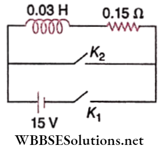
Question 29. An inductor (L = 0.03 H) and a resistor (R = 0.15kΩ) are connected in series to a battery of 15 V in a circuit shown below. The key K1 has been kept closed for a long time. Then at t = 0, K1 is opened and key K2 is closed simultaneously. At t = 1 ms, the current in the circuit will be (e5 ≈ 150)
- 100 mA
- 67 mA
- 6.7 mA
- 0.67 mA
Answer: 4. 0.67 mA
When the key K1 is closed, current through the inductor,
∴ \(I_0=\frac{e}{R}=\frac{15}{0.15 \times 10^3}=0.1 \mathrm{~A}\)
Here, t = 1 ms = 1-3 s
The time constant of the LR circuit,
∴ \(t_0=\frac{L}{R}=\frac{0.03}{0.15 \times 10^3}=2 \times 10^{-4} \mathrm{~s}\)
∴ \(\frac{t}{t_0}=\frac{10^{-3}}{2 \times 10^{-4}}=5\)
∴ \(I=I_0 e^{-t / t_0}=0.1 e^{-5}=\frac{0.1}{150}=0.67 \times 10^{-3} \mathrm{~A}\)
= 0.67 mA
The option 4 is correct
Question 30. An LCR circuit is equivalent to a damped pendulum. In an LCR circuit, the capacitor is charged to Q0 and then connected to the L and R as shown below:
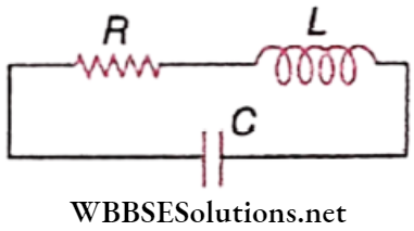
If a student plots graphs of the square of maximum charge (Q2max) on a capacitor with time (t) for two different values L1 and L2(L1 > L2) of L then which of the following represents this graph correctly? (Plots are schematic and not drawn to scale)
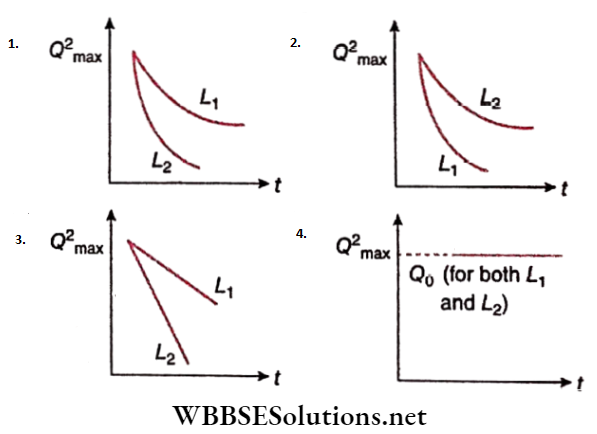
Answer: 1.
Damping of the charge of the capacitance occurs at an exponential rate.
Also, the greater the value of L, the greater the energy loss due to R.
The option 1. is correct.
Question 31. An arc lamp requires a direct current of 10 A at 80V to function. It is connected to a 220 V (rms), 50Hz ac supply, and the series inductor needed for it to work close to
- 80 H
- 0.08 H
- 0.044 H
- 0.065 H
Answer: 4. 0.065 H
When the clamp functions with dc, V = 80V, I = 10 A
Therefore, resistance of the lamp, \(R=\frac{V}{I}=\frac{80}{10}=8 \Omega\)
When the lamp and the inductor are connected to an ac source, the impedance of the circuit,
∴ \(Z=\sqrt{R^2+\omega^2 L^2}\)
The electric current in the circuit,
∴ \(I=\frac{V^{\prime}}{Z}=\frac{V^{\prime}}{\sqrt{R^2+\omega^2 L^2}} \text { or, } R^2+\omega^2 L^2=\left(\frac{V^{\prime}}{I}\right)^2\)
or, \(8^2+\omega^2 L^2=\left(\frac{220}{10}\right)^2 \text { or, } \omega^2 L^2=(22)^2-8^2\)
or, \(L=\frac{\sqrt{22^2-8^2}}{\omega}=\frac{\sqrt{30 \times 14}}{2 \pi \times 50}=0.065 \mathrm{H}\)
The option 4 is correct.
Question 32. For an RLC circuit driven with a voltage of amplitude vm and frequency \(\omega_0=\frac{1}{\sqrt{L C}}\) the current exhibits resonance. The quality factor, Q is given by
- \(\frac{R}{\left(\omega_0 C\right)}\)
- \(\frac{C R}{\omega_0}\)
- \(\frac{\omega_0 L}{R}\)
- \(\frac{\omega_0 R}{L}\)
Answer: 3. \(\frac{\omega_0 L}{R}\)
Q factor of RLC circuit = \(\frac{\omega_0}{\Delta \omega}=\frac{\omega_0}{\frac{R}{L}}=\frac{\omega_0 L}{R}\)
The option 3 is correct.
Question 33. In an ac circuit, the instantaneous emf and current is given by e = 100 sin 30t; \(i=20 \sin \left(30 t-\frac{\pi}{4}\right)\).
In one cycle of ac, the average power consumed by the circuit and the wattless current are, respectively
- \(\frac{50}{\sqrt{2}}, 0\)
- 50,0
- 50,10
- \(\frac{1000}{\sqrt{2}}, 10 \)
Answer: 4. \(\frac{1000}{\sqrt{2}}, 10 \)
⇒ \(P_{\mathrm{avg}}=e_{\mathrm{rms}} i_{\mathrm{rms}} \cos \phi_{3 \mathrm{~b}}=\frac{100}{\sqrt{2}} \times \frac{20}{\sqrt{2}} \times \frac{1}{\sqrt{2}}\left [∵ \phi_{9 \mathrm{rg}}, \frac{\pi}{4}\right]\)
= \(=\frac{1000}{\sqrt{2}}\)
The wattless current, \(i=i_{\mathrm{rms}} \cos \phi=\frac{20}{\sqrt{2}} \times \frac{1}{\sqrt{2}}=10\)
The option 4 is correct.
Question 34. A transformer having an efficiency of 90% is working on 200V and 3kW power supply. If the current in the secondary coil is 6A, the voltage across the secondary coil and the current in the primary coil respectively are
- 300V, 15A
- 450V, 15A
- 450V, 13.5A
- 600V, 15A
Answer: 2. 450V, 15A
Power of the secondary coil, Ps = VpIp
∴ \(I_p=\frac{3 \times 1000}{200}=15 \mathrm{~A}\)
Power of the secondary coil, Ps = V$IS
∴ \(V_s=\frac{P_s}{I_s}=\frac{P_p \times \frac{90}{100}}{6}=3 \times 1000 \times \frac{90}{100} \times \frac{1}{6}=450 \mathrm{~V}\)
The option 2 is correct.
Question 35. A resistance R draws power P when connected to an ac source. If an inductance is now placed in series with the resistance, such that the impedance of the circuit becomes Z, the power drawn will be:
- \(P\left(\frac{R}{Z}\right)^2\)
- \(P \sqrt{\frac{R}{Z}}\)
- \(P\left(\frac{R}{Z}\right)\)
- P
Answer: 1. \(P\left(\frac{R}{Z}\right)^2\)
The rms currents in the first and second cases are \(I=\frac{E}{R} and I^{\prime}=\frac{E}{Z}\), respectively.
∴ The pure inductor does not draw any power, then the respective powers drawn are \(P=I^2 R=\left(\frac{E}{R}\right)^2 R=\frac{E^2}{R}\)
and \(P^{\prime}=I^{\prime 2} R=\left(\frac{E}{Z}\right)^2 R=\frac{E^2}{R}\left(\frac{R}{Z}\right)^2=P\left(\frac{R}{Z}\right)^2\)
Option 1 is correct.
Question 36. A small signal voltage V(t) = V0 sinty t is applied across an ideal capacitor C.
- Over a full cycle, the capacitor C does not consume any energy from the voltage source
- Current I(t) is in phase with voltage V(t)
- Current I(t) leads voltage V(t) by 180°
- Current I(t) lags voltage V(t) by 90°
Answer: 1. Over a full cycle, the capacitor C does not consume any energy from the voltage source
The option 1 is correct
Question 37. An inductor 20mH, a capacitor 50 μF, and a resistor 40 Ω connected in series across a source of emf V = 10 sin 340 t. The power loss in ac circuit is
- 0.67W
- 0.76W
- 0.89W
- 0.51 W
Answer: 4. 0.51 W
Here, ω = 340 Hz
Inductive reactance, XL = ωL = 340 x 20 x 10-3 = 6.8H
Capacitive reactance, \(X_C=\frac{1}{\omega C}=\frac{1}{340 \times 50 \times 10^{-6}}=58.8 \Omega\)
Resistance, R = 40 Ω
Therefore, the impedance of the circuit,
∴ \(Z=\sqrt{R^2+\left(X_C-X_L\right)^2}\)
= \(\sqrt{40^2+(58.8-6.8)^2}=65.6 \Omega\)
Now, rms value of current, \(I_{\mathrm{rms}}=\frac{V_{\mathrm{rms}}}{Z}=\frac{10}{\sqrt{2} \times 65.6}\)
Power dissipated in the circuit,
P = \(V_{\mathrm{rms}} I_{\mathrm{rms}} \cos \theta=V_{\mathrm{rms}} I_{\mathrm{rms}} \frac{R}{Z}\)
= \(\frac{10}{\sqrt{2}} \times \frac{10}{\sqrt{2} \times 65.6} \times \frac{40}{65.6}=0.46 \mathrm{~W} \approx 0.51 \mathrm{~W}\)
The option 4 is correct.
Short Answer Questions on AC Voltage and Current Relationships
Question 38. An inductor 20 mH, a capacitor 100 μF, and a resistor 50 Ω are connected in series across a source of emf, V= 10 sin 314t. The power of the circuit is
- 2.74 W
- 0.43 W
- 0.79 W
- 1.13 W
Answer: 3. 0.79 W
∴ \(Z=\sqrt{R^2+\left(\omega L-\frac{1}{\omega C}\right)^2}\)
= \(\sqrt{(50)^2+\left[314 \times 20 \times 10^{-3}-\frac{1}{314 \times 100 \times 10^{-6}}\right]^2}\)
= 56.16 Ω
The power loss in the circuit,
∴ \(P=\left(\frac{V_{\mathrm{rms}}}{Z}\right)^2 \cdot R=\left(\frac{\frac{10}{\sqrt{2}}}{56.16}\right)^2 \times 50=0.79 \mathrm{~W}\)
The option 3 is correct.
Question 39. An alternating voltage given by V = 140 sin 314t is connected across a pure resistor of 50 Ω. Find
- The frequency of the source
- The rms current through the resistor.
Answer:
V = 140 sin 314t = V0 sin ωt
1. Frequency of the source,
∴ \(n=\frac{\omega}{2 \pi}=\frac{314}{2 \times 3.14}=50 \mathrm{~Hz}\)
2. \(I=\frac{V}{R}=\frac{140}{50} \sin 314 t=2.8 \sin 314 t=I_0 \sin \omega t\)
∴ \(I_{\mathrm{rms}}=\frac{I_0}{\sqrt{2}} \approx \frac{2.8}{1.4}=2 \mathrm{~A}\)
Question 40.
- For a given ac i = im sin ωt, show that the average power dissipated in a resistor R over a complete cycle is \(\frac{1}{2} i_m^2 R\)
- A light bulb is rated at 100 W for a 220 V ac supply. Calculate the resistance of the bulb.
Answer:
1. i = im sin cot, so v = im R sin cot
Power dissipated, P = vi = i2mRsin2cot
The average of sin2tot over a complete cycle = \(\frac{1}{2}\)
∴ Average power dissipated,
= \(\bar{P}=i_m^2 R \cdot \frac{1}{2}=\frac{1}{2} i_m^2 R\)
2. \(P=\frac{V^2}{R} \quad \text { or, } R=\frac{V^2}{P}=\frac{(220)^2}{100}=484 \Omega\)
Question 41. Why is the use of ac voltage preferred over dc voltage? Give two reasons.
Answer:
- Alternating voltages can be stepped up or down quite easily.
- Alternating power can be transmitted over a long distance with very small thermal loss using a high voltage-low current ac supply.
Question 42. A voltage V = V0sincut is applied to a series LCR circuit Derive the expression for the average power dissipated over a cycle. Under what condition is
- No power dissipated even though the current flows through the circuit,
- Maximum power dissipated in the circuit?
Answer:
- No power is dissipated if the pure resistance R in the circuit is zero.
- Maximum power is dissipated if the inductive and capacitative reactances cancel each other i.e., when the circuit impedance becomes equal to the pure resistance of the circuit(Z = R).
Question 43. In a series LR circuit, XL = R, and the power factor of the circuit is P1. When a capacitor with capacitance C such that XC = XL is put in series, the power factor becomes P2. Find out P1/P2.
Answer:
In a series LR circuit, power factor \(\left(P_1\right)=\frac{R}{Z}\)
Here, Z = impedance = \(\sqrt{R^2+X_L^2}\)
Here, \(Z=\sqrt{R^2+R^2}=\sqrt{2} R\)
∴ \(P_1=\frac{1}{\sqrt{2}}\)
In a series LCR Circuit, power factor \(\left(P_2\right)=\frac{R}{Z}\)
Where \(Z=\sqrt{R^2+\left(X_L-X_C\right)^2}=R\)
∴ P2 = 1
Hence, \(\frac{P_1}{P_2}=\frac{1}{\sqrt{2}}\)
Question 44.
- When an ac source is connected to an ideal capacitor, show that the average power supplied by the source over a complete cycle is zero.
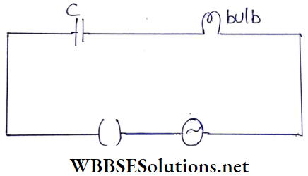
- A bulb is connected in series with a variable capacitor and an ac source as shown. What happens to the brightness of the bulb when the key is plugged in and the capacitance of the capacitor is gradually reduced?
Answer:
1. The instantaneous power supplied to the capacitor,
P = I0 cos(ωt) V0 sin(ωT)
P = I0 V0 cos(ωt) sin(ωt)
∴ \(P=\frac{I_0 V_0}{2} \sin (2 \omega t)\)
Therefore, the average power,
∴ \(\bar{P}=\frac{I_0 V_0}{2} \sin (2 \omega t)=\frac{I_0 V_0}{2} \sin (2 \omega t)\)
Now, the average of sin( 2<wt) over the cycle is zero.
∴ \(\bar{P}=0\)
2. The capacitance of the capacitor is gradually reduced. Therefore, the capacitive reactance \(X_C=\frac{1}{2 \pi f C}\) increases.
Therefore, essentially, the overall resistance of the circuit increases. This causes a reduction in the amount of current flowing through the circuit. Therefore, the brightness of the bulb reduces.
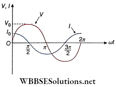
Question 45. A device X is connected to an ac source V = V0 sin ωt. The variation of voltage, current, and power in one cycle is shown in the following graph:
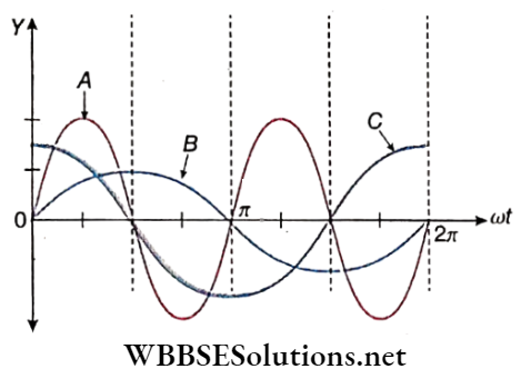
- Identify the device X
- Which of the curves A, B, and C represent the voltage, current, and power consumed in the circuit? Justify your answer.
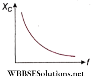
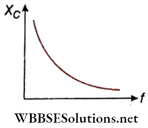
- How does its impedance vary with the frequency of the ac source? Show graphically.
- Obtain an an expression for the current in the circuit and its phase relation with ac voltage
Answer:
1. Device X is a capacitor.
2. B represents voltage because it is a sine wave. C represents current because current leads voltage by \(\frac{\pi}{2}\). A represents power because the average power cycle is zero.
3. Impendance, \(X_C=\frac{1}{\omega C}=\frac{1}{2 \pi f C}\)
4. \(C=\frac{q}{V}\)
∴ q = CV = CV0 sinωt [∵ V = V0sin t]
∴ Current, \(I=\frac{d t}{d q}=\frac{d}{d t}\left(C V_0 \sin \omega t\right)=\omega C V_0 \cos \omega t\)
= \(\frac{V_0}{\frac{1}{\omega C}} \cos \omega t\)
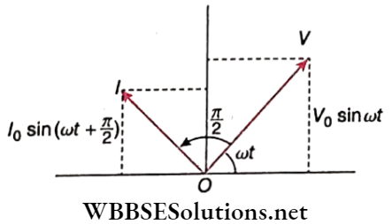
∴ \(I=\frac{V_0}{\dot{X}_C} \sin \left(\omega t+\frac{\pi}{2}\right) \quad \text { or, } I=I_0 \sin \left(\omega t+\frac{\pi}{2}\right)\)
In a pure capacitive circuit current leads voltage by \(\frac{\pi}{2}\).
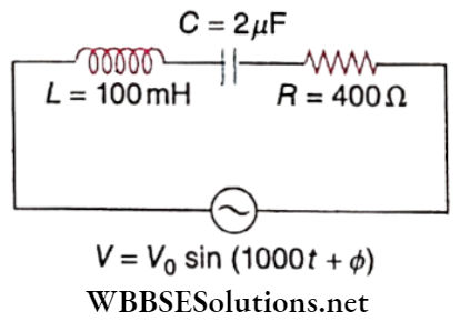
Question 46. Find the value of the phase difference between the current and the voltage hi the series LCR circuit shown below. Which one leads in phase: current or voltage?
Answer:
Given, V = V0 sin(1000t +Φ), R = 4000, C = 2μF,
L = 100 mH.
The standard equation is given by,
V = V0 sin (ωt + Φ)
∴ ω = 1000 Hz
Now, XL = ωL= 1000 x 100 x 10-3 = 102 = 100Ω
and \(X_C=\frac{1}{\omega C}=\frac{1}{1000 \times 2 \times 10^{-6}}=500 \Omega\)
The phase difference between the current and the voltage in the series LCR circuit is given by,
∴ \(\phi=\tan ^{-1}\left(\frac{X_C-X_L}{R}\right)\)
or, \(\phi=\tan ^{-1}\left(\frac{500-100}{400}\right)=\tan ^{-1} 1\)
∴ Φ = 45°
Since, XC > XL, therefore current leads in phase.
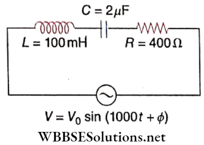
Question 47. Without making any other change, find the value of the additional capacitor, to be connected in parallel with the capacitor C, to make the power factor of the circuit unity.
Answer:
To make the power factor of the circuit unity,
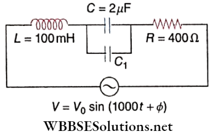
XC = XL
∴ \(\frac{1}{\omega\left(C+C_1\right)}=100 \text { or, } \frac{1}{1000\left(C+C_1\right)}=100\)
or, \(C+C_1=\frac{1}{10^5}\)
or, \(C_1=\frac{1}{10^5}-C=10^{-5}-0.2 \times 10^{-5}=0.8 \times 10^{-5}\)
or, C1 = 8μF
Concepts of Phase Difference in Alternating Current
Question 48.
- Draw a labeled diagram of a step-up Transformer. Obtain the ratio of secondary to primary voltage in terms of several turns and currents in the two coils.
- A power transmission line feeds input power at 2200 V to a step-down transformer with its primary windings having 3000 turns. Find the number of turns in the secondary to get the power output at 220 V.
Answer:
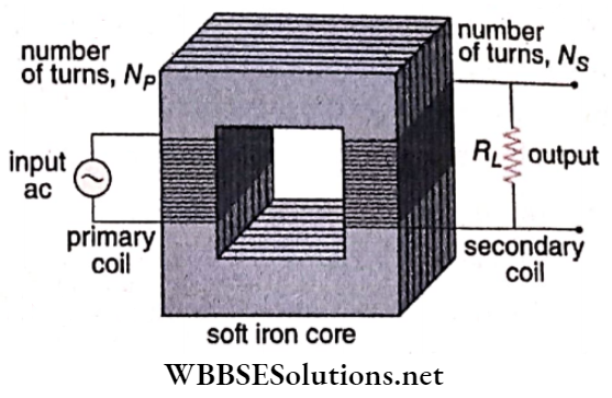
1. When an alternating potential Vp is applied to the primary coil, an emf (ep) is induced in it.
∴ \(e_p=-N_p \frac{d \phi}{d t}\)
It resistance of the primary coil is low, Vp = ep
∴ \(V_p=-N_p \frac{d \phi}{d t}\)
As the same flux is linked with the secondary coil with the help of a soft iron core due to mutual induction, emf (es) is induced in it.
∴ \(e_s=-N_s \frac{d \phi}{d t}\)
If the output circuit is open then, Vs = es
∴ \(V_s=-N_s \frac{d \phi}{d t}\)
Thus, \(\frac{V_s}{V_p}=\frac{N_s}{N_p}\)
For an ideal transformer, Pout = Pin
or, IsVs = IpVp
∴ \(\frac{V_s}{V_p}=\frac{I_p}{I_x}=\frac{N_s}{N_p}\)
For setup transformer \(\frac{N_s}{N_p}>1\).
In the case of dc voltage, flux does not change. Thus no emf is induced in the circuit.
2. Given, Vp = 2200 V, Np = 3000, Vs = 220 V
We know, \(\frac{V_s}{V_p}=\frac{N_s}{N_p} \quad \text { or, } N_s=\frac{N_p \cdot V_s}{V_p}=\frac{3000 \times 220}{2200}\)
∴ Ns = 300
Question 49. A device X is connected across an ac source of voltage V= V0sincot. The current through X is given as \(I=I_0 \sin \left(\omega t+\frac{\pi}{2}\right)\).
- Identify the device X and write the expression for its reactance.
- Draw graphs showing variation of voltage and current with time over one cycle of ac, for X.
- How does the reactance of device X vary with the frequency of the ac? Show this variation graphically.
- Draw the phasor diagram for the device X.
Answer:
1. Device X is a capacitor
∴ Capacitive reactance, \(X_C=\frac{1}{\omega C}=\frac{1}{2 \pi f C}\)
Question 50. The teachers of Geeta’s school took the students on a study trip to a power generating station, located nearly 200 km away from the city. The teacher explained that electrical energy is transmitted over such a long distance to their city, in the form of alternating current (ac) raised to a high voltage. At the receiving end in the city, the voltage is reduced to operate the devices. As a result, the power loss is reduced. Geeta listened to the teacher and asked questions about how the ac is conveyed to a higher or lower voltage.
- Name the device used to change the alternating voltage to a higher or lower value. State one cause for power dissipation in this device.
- Explain with an example, how power loss is reduced if the energy is transmitted over long distances as an alternating current rather than a direct current.
- Write two values each shown by the teachers and Geeta.
Answer:
1. 1st part: A Transformer is a device used to change the alternating voltage to a higher or lower value. 2nd part: One cause for power dissipation in this device is copper loss. Generally, copper wire is used to make primary and secondary coils. Due to Joule’s heating, some energy is dissipated as heat energy.
2. At the electric power producing station, a set-up transformer is used to increase the alternating voltage up to several kilovolts. So the electric current flowing through transmission wires decreases. As Joule’s heating is proportional to the square of current, the loss of electrical energy across transmission wires decreases due to a decrease in current.
3. Two values shown by teachers are
- sense of responsibility,
- good practical knowledge. Two values shown by Geeta are—
- curiosity to learn,
- critical thinking.