Electromagnetic Induction And Alternating Current
Electromagnetic Induction Induced Emf Or Induced Induction
When a current-carrying wire is placed in a magnetic field, it is deflected, i.e., a motion is generated. An opposite phenomenon was first observed by Michael Faraday.
He saw that if a closed wire loop is moved in a magnetic field, an electric current is generated in that loop as long as the motion continues.
Definition: If there is a relative motion between a magnetic field and a conductor, an electromotive force is generated in the conductor. It is called induced electromotive force.
It should be noted carefully that, to get electric current from this induced emf, the conductor should be in the form of a closed circuit.
This is because, the resistance of an open circuit is infinite and hence, despite the presence of induced emf, no current passes through the conductor.
Definition: If there is a relative motion between a magnetic field and a closed circuit conductor, the current flowing through that conductor is known as induced current.
Electromagnetic induction: The phenomenon involving the generation of electrical energy due to relative motion between a magnetic field and a conductor is called electromagnetic induction.

Electromagnetic Induction And Alternating Current
Electromagnetic Induction Experimental Demonstration
Magnitude And Direction Of Induced Current
Induced current with the help of a magnet: In Fig. 1.1, C is a circular coil having one or more turns. M is a permanent magnet kept along the axis of C. G is a galvanometer connected to C.
By observing the deflection of the pointer in G towards left or right, the direction of current in the coil C (i.e., anticlockwise or clockwise) can be determined.
Again, noting the extent of deflection of the pointer (i.e.,
low or high), the magnitude of the current, low or high, can be ascertained.
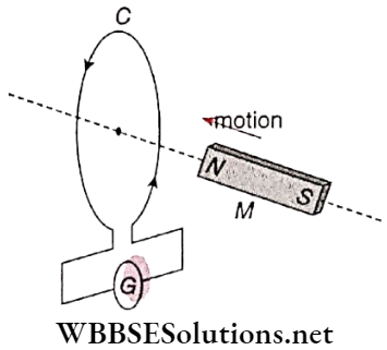
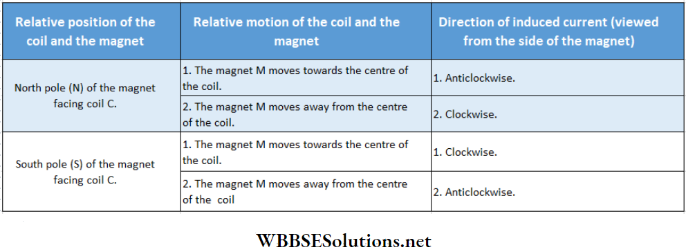
For different motions of the magnet along the axis of the coil, the directions of induced current through the coil are given in the following table.
WBBSE Class 12 Electromagnetic Induction Notes
Note that, no induced current is noticed in the coil when
- The magnet is at rest, the magnet rotates about its axis or
- Both the magnet and this coil move in such a way that no relative motion exists between them.
- Keeping the magnet at rest, if the coil is moved towards or away from the magnet, the same results will be obtained.
Direction Of The Induced Electromotive Force:
This direction depends on
- The nature of the magnetic pole facing the conductor and
- The direction of motion of the magnet concerning the conductor.
Magnitude Of The Induced Electromotive Force:
- Increases with an increase in the relative velocity between the coil and the magnet.
- Increases with the increase in pole strength of the magnet.
- Increases with an increase in the number of turns of the coil.
Magnitude And Direction Of The Induced Current:
- The direction is identical to the direction of induced electromotive force.
- Magnitude is directly proportional to the magnitude of the induced emf
- Magnitude is directly proportional to the magnitude of the induced emf.
- Inversely proportional to the resistance of the coil.
Note that, induced electromotive force does not depend on the resistance of the circuit. In an open circuit, the resistance is infinite, hence no current passes but the induced emf associated with the circuit does exist.
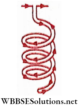
Current Induced With The Help Of Current Carrying Conducting Coil Or Current Carrying Solenoid:
A current-carrying circular coil or a current-carrying solenoid is equivalent to a permanent magnet. The rule for determination of their poles are
- If the current view from a face is anticlockwise, that face acts as a north pole (N) and
- If the current view from a face is clockwise, that face acts as a south pole (S).
So, if a circular current-carrying coil or a current-carrying solenoid is used instead of the magnet M shown, the same experimental result will be obtained. Two more important facts should be noted:
- With the increase in the current through the circular coil or solenoid, the strength of the magnetic field increases.
- If the direction of current through the circuit is reversed, magnetic polarity is also reversed.
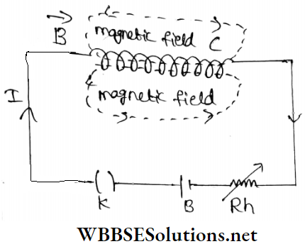
Current Induced With The Help Of Static Electrical Circuits:
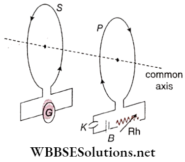
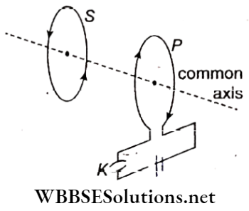
In S is a circular coil with one or more turns. A galvanometer G is connected to it. From this galvanometer, the magnitude and direction of the induced current can be determined.
P is another co-axial circular coil connected with an electrical circuit. B is a battery and a key K is used to switch on or off the circuit. Again, with the help of the rheostat, current through the circuit can be increased or decreased.
Now, if the circuit P be switched ‘on’ or if the current in the circuit is increased rapidly, the magnetic field also increases considerably.
It is similar to the situation when a magnet is moved towards the coil S swiftly. So, the results of two phenomena: ‘increase of current in the circuit P’ and ‘relative motion between the coil S and the magnetic field’ are identical.
Naturally, if the circuit P is switched ‘off’ suddenly or if the current in the circuit is decreased rapidly, the effective relative velocity becomes just opposite to the former case.
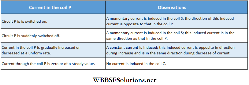
Observation:
the current through coil P be increased or decreased in different ways using the key K and the rheostat Rh, the induced current found the coil S will be as described below:
Short Notes on Faraday’s Law of Induction
Primary And Secondary Coils:
In the experiment shown, the current through coil P is the cause of electromagnetic induction and this coil is called the primary coil.
On the other hand, the current in coil S is the result of electromagnetic induction and this coil is called the secondary coil.
Electromagnetic Induction And Alternating Current
Electromagnetic Induction Magnetic Induction And Magnetic Flux
From the discussion of magnetism we know that, if a magnetic material is placed in an external magnetic field, it gets magnetically induced.
This magnetic induction is a vector quantity, and the most convenient way to specify its magnitude and direction is to draw lines of induction through that substance.
If the magnetic induction is greater at a place, lines of induction get crowded there. Moreover, the direction of lines of induction is to be represented.
According to the direction of magnetic induction at every point. From this we can define magnetic induction as follows:
Definition: The number of lines of induction passing normally through a unit area surrounding a point inside a substance is called magnetic induction at that point.
Magnetic induction is a vector quantity, its symbol is \(\vec{B}\). This vector is identical to the magnetic field \(\vec{B}\) described in the chapter ‘Electromagnetism.
Usually, the lines of induction passing through any medium are called lines of force. These continuous lines of force passing through a medium can be imagined as a kind of stream.
This stream is comparable to the flow of water. We know that, in the case of water flow, the rate of flow of water can be obtained from the mass of water passing through any cross-section. Magnetic flux can be defined from this analogy.
Definition: The number of lines of induction passing normally through any surface placed in a magnetic field is called the magnetic flux linked with that surface.
Magnetic flux is a scalar quantity, and its symbol is Φ.
Let the area of a surface placed in a uniform magnetic field be A. If the magnetic induction \(\vec{B}\) is inclined at an angle θ with the normal to the surface, the component of \(\vec{B}\) in the direction of that normal is Bcosθ (magnitude of \(\vec{B}\) is B).
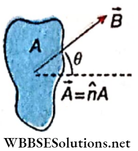
Hence according to the definition, of magnetic flux,
⇒ \(\phi=B A \cos \theta=\vec{B} \cdot \vec{A}=\vec{B} \cdot \hat{n} A\)
where \(\hat{n}\) is a unit vector normal to the surface.
For a finite surface, we first consider the magnetic flux through an infinitesimal area \(d \vec{A}\). The magnetic flux across this area, \(d \phi=\vec{B} \cdot d \vec{A}\)
A finite surface A can be assumed as the summation of such infinitesimal elements and the magnetic flux through the total surface area,
∴ \(\phi=\int_S \vec{B} \cdot d \vec{A}\)
Special Cases:
If the lines of induction are along the surface, then θ = 90° and hence Φ = 0.
If the lines of induction are perpendicular to the surface, θ = 0° and hence Φ = BA. In this case, \(B=\frac{\phi}{A}\) = magnetic flux linked with unit area.
Thus, magnetic induction \(\vec{B}\) is also called magnetic flux density. According to this flux is positive.
If θ = 180°, Φ = -BA i.e., flux is negative.
Electromagnetic Induction And Alternating Current
Electromagnetic Induction Laws Of Electromagnetic Induction
The phenomenon of electromagnetic induction is completely described by three laws. The exact information obtained from these laws is as follows:
- Whether or not an emf would be induced in a coil (Faraday’s 1st law).
- The magnitude of this induced emf (Faraday’s 2nd law).
- The direction of the induced emf (Lenz’s law)
Faraday’S Laws
First law: Whenever the magnetic flux linked with a coil changes with time, an electromotive force is induced in the coil. Induced EMF lasts as long as the magnetic flux linked with the coil continues to change.
Second law: The magnitude of the induced is directly proportional to the time rate of change of magnetic flux linked with the coil.
If the change in magnetic flux linked with a coil in time dt be dtb, according to Faraday’s second law,
induced emf \(e \propto \frac{d \phi}{d t}\) → (1)
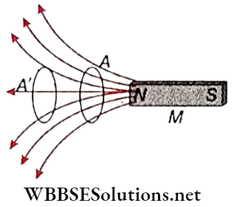
Explanation Of Faraday’s Two Laws: The magnetic lines of force or lines of. induction adjacent to the north pole (IV) of a bar magnet M is shown.
Explanation Of The First Law:
If a closed coil is moved from A to A’ or from A’ to A, the number of lines of force through that coil, i.e., magnetic flux linked with it decreases or increases, respectively.
According to Faraday’s first law, during the motion of the coil in both cases an emf will be induced in the coil: On the other hand, if the coil is at rest, no change in the magnetic flux will occur, and hence induction will not take place.
From the experiment of electromagnetic induction, the same result is obtained. So, from the first law, the cause of the electromagnetic induction and the time of existence of the induced emf can be ascertained.
Explanation Of The Second Law: If the relative velocity between the coil and the magnet is increased, the strength of induced emf also increases. This phenomenon is by Faraday’s second law, because if the coil is moved quickly the rate of change of the number of lines of force, i.e., the rate of change of magnetic flux also increases. So, the second law determines the magnitude of the induced emf.
Lenz’s Law
From Faraday’s laws, the direction of the induced emf cannot be ascertained. The necessary law for the determination of this direction is Lenz’s law. This may be called the third law of electromagnetic induction.
Statement: In the case of electromagnetic induction, the direction of the induced emf is such that, it always opposes the cause of induction in the circuit.
Important Definitions in Electromagnetic Induction
Explanation of Lenz’s law:
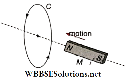
Relative motion between a magnet and a closed coil:
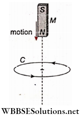
Let C be a circular conducting coil. Along its axis, the north pole (AO of a bar magnet M is moved towards the coil.
According to Lenz’s law, the induced current in C will oppose the motion of the magnet M, i.e., it will repel the magnet. For this, a north pole would be generated on the front face of the coil.
So, if viewed from the side of the magnet, the induced current will be anticlockwise. Similarly, if the magnet is moved in the opposite direction the current in the coil C will be clockwise.
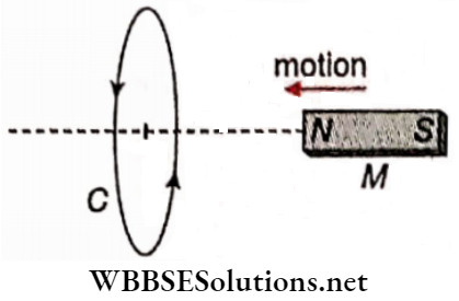
If magnet M is moved forward beyond the surface of coil C, the induced current in the coil will attract the south poles of the magnet.
Hence, a north pole should be generated on the back face of the coil and a south pole on the front face. So, if Viewed from the front face, the induced current is clockwise.
Primary And Secondary Coils:
let a current be passed through the primary coil P by switching on the circuit. At that moment.
The instantaneous effect on the secondary coil becomes similar to the effect due to a sudden rapid movement of a current-carrying coil towards the secondary coil.
So, according to Lenz’s law, the induced current in the secondary coil S will repel the primary coil. Since two unlike parallel currents repel each other.
We can conclude that the induced current in the secondary coil is opposite in direction concerning the primary coil.
On the other hand, if the primary circuit is switched off; just at that moment, a like current will be induced in the secondary coil.
Falling Of A Magnet Through A Coil: when a body is allowed to fall freely in the gravitational field of the earth, it falls with „ acceleration due to gravity (g).
Let us consider a closed circular coil C kept horizontally and along its axis, a bar magnet M is released. Due to the downward motion of the magnet, an induced current is set up in coil C.
According to Lenz’s law, the direction of this induced current will be such that, the downward motion of the magnet will be opposed. As a result, the magnet will fall with a smaller acceleration than that due to gravity (g).
If the coil is replaced by a long cylindrical conductor (say, a copper pipe), the slower motion of the magnet becomes more dearly noticeable.
Lenz’s Law From The Law Of Conservation Of Energy:
Let a bar magnet M be moving towards a closed coil C along its axis. Its north pole faces the coil. As a result, a current is induced in the coll, i.e., electrical energy is developed.
According to the law of conservation of energy, this electrical energy can only be obtained at the cost of other forms of energy and hence some external positive work is to be done against an opposing force.
The current induced in the coil is the source of this opposing force. Naturally, the direction of the induced current has to be anticlockwise to develop.
An N pole in its front face will oppose the motion of the bar magnet. So, Lenz’s law is a natural consequence of the law of conservation of energy.
Law Of Conservation Of Energy From Lenz’s Law:
According to Lenz’s law, the direction of the induced emf is such that, this induced emf can oppose the cause of the generation of electric current in the circuit.
It means that if we gradually bring a magnet near the coil, the induced EMF will oppose the forward motion, and when the magnet is taken away from the coil, it opposes that receding motion.
As a result, to generate relative motion between the magnet and the coil, some work must be done against this opposing force and this work will induce electromotive force to obey the principle of conservation of energy.
Hence, the principle of conservation of energy can be obtained from Lenz’s law.
Expression For Induced Electromotive Force
From Faraday’s second law we know that, if the change in magnetic flux linked with a closed conductor be dtp in time dt, induced emf, \(e \propto \frac{d \phi}{d t}\)
So, according to Lenz’s law, we can write,
\(e=-k \frac{d \phi}{d t}\) → (1)
Here, k is a positive constant. Since the induced emf e opposes the change in magnetic flux dΦ, a negative sign is used in the equation.
Note that, equation (1) expresses the three laws of electromagnetic induction simultaneously.
- If magnetic flux does not change i.e. if dΦ = 0 then e = 0. This supports Faraday’s first law.
- \(e \propto \frac{d \phi}{d t}\).It is Faraday’s second law. For a coil having n turns, \(e \propto n \frac{d \phi}{d t}\).
- The ‘negative’ sign on the right-hand side of equation (1) indicates the opposing nature of induced emf e due to the change in magnetic flux d<t>. This is Lenz’s law.
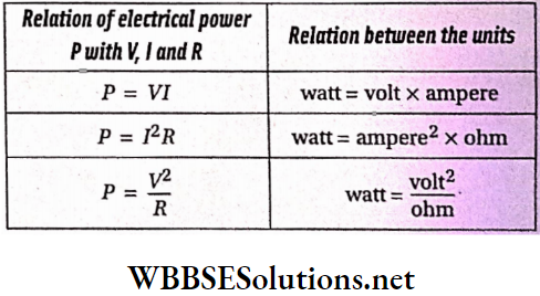
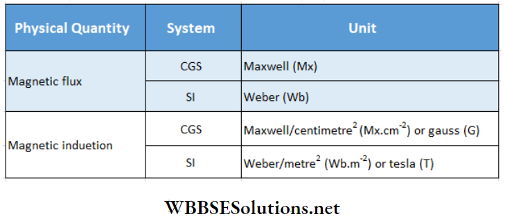
Units Of Magnetic Flux And Magnetic Induction:
The unit of magnetic flux is so defined that the magnitude of the
constant k in equation (1) becomes 1
For \(e=1, \text { if } \frac{d \phi}{d t}=1, \text { then } k=1\)
In that case \(e=-\frac{d \phi}{d t}\) → (2)
So, the unit of magnetic flux is defined as the change in unit time of magnetic flux linked with a conducting coil, for which 1 unit emf is induced in that coil.
Again, since the magnetic flux linked with the unit area is called magnetic induction or magnetic flux density, the unit of magnetic induction or magnetic flux density = \(\frac{\text { unit of magnetic flux }}{\text { unit of area }}\)
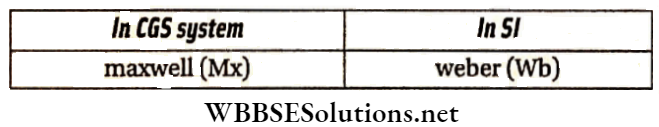
1 Wb: The change of magnetic flux linked with a coil in 1 s, for which 1 V emf is induced in the coil, is called 1 Wb.
In other words, 1 Weber is the magnetic flux which, linking a circuit of one turn, would produce in it an electromotive force of 1 volt if it were reduced to zero at a uniform rate in 1 second.
1 Mx: The change of magnetic flux linked with a coil in 1 s, for which 1 abvolt (1 abvolt = 10~8 V) emfis induced in the coil, is called 1 Mx.
In other words, 1 maxwell is the magnetic flux which, linking a circuit of one turn, would produce in it an electromotive force of 1 aibvolt if it were reduced to zero at a uniform rate in 1 second.
Relation Between Different Units:
As l volt = 108 abvolt
so, 1 Wb = 108 Mx .
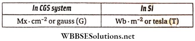
Again, 1 T = \(\frac{1 \mathrm{~Wb}}{1 \mathrm{~m}^2}=\frac{10^8 \mathrm{Mx}}{10^4 \mathrm{~cm}^2}\)
= 104 Mx.cm-2 = 104 G
Relation between web and V: According to the relation,
⇒ \(e=\frac{d \phi}{d t}\),
∴ \(\mathrm{V}=\frac{\mathrm{Wb}}{\mathrm{s}}\) or, Wb = V.s
Amount Of Change Flowing Through A Closed Circuit For Induced Electromotive Force:
Let the number of turns of any closed coil be n, the emf induced in the coil be e and the rate of change of magnetic flux linked with the coil be \(\frac{d \phi}{d t}\). Now, if the resistance of the circuit is R, the current induced in it (taking the magnitude only),
∴ \(i=\frac{e}{R}=\frac{n}{R} \cdot \frac{d \phi}{d t}\) [∵ e = \(n \frac{d \phi}{d t}\)]
Or, \(i d t=\frac{n}{R} \cdot d \phi\) → (3)
If the initial magnetic flux linked with the coil be and the final magnetic flux linked be <p2, then integrating equation (3) we get,
⇒ \(\int_0^t i d t=\frac{n}{R} \int_{\phi_1}^{\phi_2} d \phi=\frac{n}{R}\left(\phi_2-\phi_1\right)\)
So, the amount of charge flowing through the circuit,
∴ \(q=\int_0^t i d t=\frac{n}{R}\left(\phi_2-\phi_1\right)\) → (4)
Electromagnetic Induction And Alternating Current
Electromagnetic Induction Numerical Examples
Example 1: A coil of resistance 100 Ω having 100 turns is placed in a magnetic field. A galvanometer of resistance 400 Ω is connected in series with it If the coil is brought from the present magnetic field to another magnetic field in \(\frac{1}{10}\)s, determine the average emf and the current. Given, the initial and final magnetic flux linked with each turn of the coil are 1 mWb and 0.2 mWb respectively.
Solution:
Change in magnetic flux for each turn
= 0.2-1 = -0.8 mWb
So, a change in magnetic flux for 100 turns
= 100 X (+0.8) mWb = -0.08 Wb
Hence, the magnitude of average emf-induced
= the negative of the rate of change of magnetic flux
= \(-\left(-\frac{0.08 \mathrm{~Wb}}{\frac{1}{10} \mathrm{~s}}\right)=0.8 \mathrm{~V}\).
The equivalent resistance of the circuit = 100 + 400 = 500 Ω
Hence, the average induced current = \(\frac{0.8 \mathrm{~V}}{500 \Omega}\) = 0.0016 A = 1.6mA.
Practice Problems on Electromagnetic Induction
Example 2. A conducting wire is wound around the great circle of a spherical Balloon. This Circular Loop Can Contract with The Balloon. A hemispherical cross-section of the balloon is shown in the figure. The initial radius of the balloon is 0.60m. A uniform magnetic field B = 0.25T exists along the perpendicular to the plane of the circular loop., in +y – direction. After 5.0 x 10⁻², the balloon is deflated to a radius of 0.30m. What will be the average EMF induced in the loop during this time?
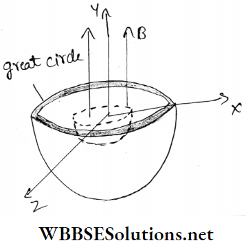
Solution: Initially the flux linked with the conducting loop along the y-axis,
⇒ \(\phi_i=\vec{B} \cdot \overrightarrow{A_i}=B A_i \cos 0^{\circ}=0.25 \pi \times 0.60^2\)
= 0.28 Wb
After deflation of the balloon, the flux linked with the conducting loop of radius 0.30m,
⇒ \(\phi_f=\vec{B} \cdot \vec{A}_f=B A_f \cos 0^{\circ}=0.25 \pi \times 0.30^2\)
= 0.070 Wb
∴ change of flux,
∴ \(\Delta \phi=\phi_f \phi_i=(0.070-0.28) \mathrm{Wb}=-0.21 \mathrm{~Wb}\)
∴ Induced emf, e = \(e=-\frac{\Delta \phi}{\Delta t}=\frac{+0.21}{5 \times 10^{-2}}=4.2 \mathrm{~V}\).
Example 3. A copper wire of diameter 0.04 in. and length 50 cm is bent in the form of a circular loop. The plane of the loop is normal to a uniform magnetic field which is increasing with time at a constant rate of 100 G.s-1. What is the rate of Joule heating in the loop? [Resistivity of copper = 1.7 X l0-8 Ω . m, 1 in. = 2.54 cm]
Solution:
The radius of the wire
= 0.02 in. = 0.02 x 2.54 x 10-2m = 5.08 x 10⁻⁴ m
Area of cross-section of the wire,
⇒ \(A_1=\pi r^2=\pi\left(5.08 \times 10^{-4}\right)^2=81 \times 10^{-8} \mathrm{~m}^2\)
Resistance of the wire,
⇒ \(R_0=\frac{\rho l}{A_1}=\frac{1.7 \times 10^{-8} \times 0.5}{81 \times 10^{-8}} \Omega\) [l =length of the wire = 0.5 m ]
= 1.05 x 10⁻² Ω
The radius of the loop,
⇒ \(R=\frac{l}{2 \pi}=\frac{0.5}{2 \pi}=7.96 \times 10^{-2} \mathrm{~m}\)
Area of the loop,
⇒ \(A=\pi R^2=3.14 \times\left(7.96 \times 10^{-2}\right)^2\)
= 0.02 m2
Here \(\frac{d B}{d t}=100 \mathrm{G} / \mathrm{s}=10^{-2} \mathrm{~Wb} \cdot \mathrm{m}^{-2} \cdot \mathrm{s}^{-1}\)
∴ Induced emf,
⇒ \(e=A \cdot \frac{d B}{d t}=(0.02) \times 10^{-2}=2 \times 10^{-4} \mathrm{~V}\)
∴ From Joule’s law, the rate of Joule heating,
⇒ \(H=I^2 R_0=\frac{e^2}{R_0}=\frac{\left(2 \times 10^{-4}\right)^2}{1.05 \times 10^{-2}}=3.8 \times 10^{-6} \mathrm{~W}\)
Electromagnetic Induction And Alternating Current
Electromagnetic Induction Motional Electromotive Force
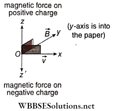
Let us assume a uniform magnetic field \(\vec{B}\) directed along the axis which is vertically downwards.
A rod PQ parallel to the z -z-axis, is moving at a constant velocity \(\vec{v}\) along the x -x-axis through this field.
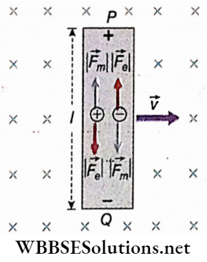
In this condition, a free charge q in the rod experiences a magnetic force, \(\vec{F}_m=q \vec{v} \times \vec{B}\). If q is a positive charge then this force is directed from Q to P (i.e., along +ve z-axis).
On the other hand, if q is negative then this force is directed from P to Q (i.e., along the -ve z-axis). Hence the free charges continue to accumulate at the ends of the rod creating a gradually increasing potential difference between P and Q.
This, in turn, creates an increasing electric field \(\vec{E}\) within the rod, in the direction from P to Q (opposite to the magnetic force). Due to this growing electric field, the electric force exerted on the charge q at any moment, Fe = qE.
As the magnitude of electric force comes to be equal with that of magnetic force, no net force anymore acts on the charge q, i.e., at equilibrium condition,
⇒ \(\left|\vec{F}_e\right|=\left|\vec{F}_m\right|\)
i.e., \(q|\vec{E}|=q|\vec{v} \times \vec{B}| \quad \text { or, }|\vec{E}|=|\vec{v} \times \vec{B}|\)
∴ \(E=v B \quad\) [∵ \(\vec{v} \perp \vec{B}]\)→ (1)
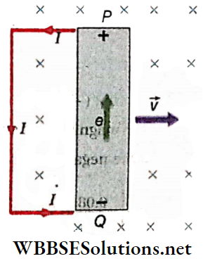
Let the potential difference between the ends P and Q be V. If the length of the rod is l then,
V = El = vBl [putting the value of E from (1) ] → (2)
Now, if the ends of the rod are connected with a conductive wire, a current is set up in the circuit. Hence the moving rod can be considered as a source of emf (e), i.e., as a cell. Just like in a cell, this emf directs from the negative end Q to the positive end p inside the road.
For an open circuit, equation (2) can be written as,
V = e = vBl → (3)
This induced EMF in the moving rod is called motional electromotive force.
In general, if θ is the angle between \(\vec{v}\) and \(\vec{B}\) then, equation (3) becomes,
e = vBlsinθ → (4)
Discussions:
Dependence Of Induced Motional Emf On Different Factors:
From the above equation (4), the emf e induced across the straight conductor moving in a magnetic field is
- Directly proportional to the magnetic induction (B),
- Directly proportional to the length (l) of the conductor,
- Directly proportional to the velocity (v) of the conductor and
- Dependent on the angle 6 between the magnetic field and the direction of motion of the conductor. If the direction of motion of the conductor is parallel to the magnetic field then, θ = 0 and e = 0, and in that case, no electromagnetic induction takes place.
For θ = 90°, the emf induced is maximum.
Emf Induced Between The Two Extremities Of The Wings Of An Aeroplane:
At different places on the earth, the geomagnetic field is not horizontal; from the values of the angle of dip, the actual direction of the geomagnetic field is known.
When an aeroplane flies in a horizontal plane above the earth’s surface, the length of its two wings repeatedly intercepts the lines of force of the geomagnetic field.
As a result, electromagnetic induction takes place, i.e., a potential difference is set up between the two extremities of its wings.
The magnitude of this potential difference depends on
- The distance between the extremities of the wings,
- The velocity of the aeroplane,
- The direction of motion of the aeroplane,
- The horizontal component and
- The angle of dip of the geomagnetic field.
The value of the angle of dip at the geomagnetic equator is zero. In this position, a horizontally moving aeroplane does not cut the geomagnetic lines of force, and hence no potential difference is set up between the extremities of the wings.
Emf Induced Between The Two Ends Of A Conductor Rotating With Uniform Angular Velocity In A Uniform Magnetic Field:
Let a conductor of length L be rotating about the point O with uniform angular speed ω in the plane of the paper. The magnetic field B is normally upwards relative to the plane of the paper.
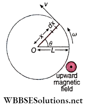
Let us consider a small element dx of the conductor at a distance x from the point 0, which is moving with velocity v perpendicular to the direction of the magnetic field. The emf induced in this element of the conductor,
de = B(dx)v [using the relation, e = Blv]
= Bωxdx [∵ v = ωx]
So, the emf induced between the two ends of the entire conductor,
∴ \(e=\int_0^L B \omega x d x=B \omega\left[\frac{x^2}{2}\right]_0^L=\frac{1}{2} B \omega L^2\)
Induced Current In A Moving Straight Conductor:
In the discussion of motional electromotive force, if R be the total resistance of the circuit then, V = IR. So, from (3) we get,
⇒ \(I R=v B l \quad \text { or, } I=\frac{v B l}{R}\) → (5)
The direction of the induced current can be determined with the help of the following simple rule.
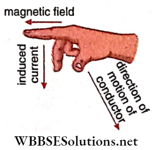
Fleming’s right-hand rule:
The thumb, the forefinger and the middle finger of the right hand are stretched perpendicular to each other.
If the magnetic field forefinger points in the direction of the magnetic field and the thumb in the direction of the motion of the conductor, then the middle finger will point in the direction of the induced current.
This rule is also called the dynamo rule.
Electromagnetic Induction And Alternating Current
Electromagnetic Induction Motional Electromotive Force Numerical Examples
Example 1. The distance between the two endpoints of the wings of an aeroplane is 5m and the aeroplane is flying parallel to the earth’s surface with a velocity of 360 km h-1. If the geomagnetic intensity is 4 x 10⁻⁴ Wb.m-2 and the angle of dip at that place is 30°, determine the emf induced between the two end-points of the wings.
Solution:
While flying horizontally, the wings of the aeroplane cut the vertical component of the earth’s magnetic field normally and hence, an emf is induced between the two ends of the wings.
This induced emf, e = Blvsinθ.
Here \(B=4 \times 10^{-4} \mathrm{~Wb} \cdot \mathrm{m}^{-2}, l=5 \mathrm{~m}\)
⇒ \(v=360 \mathrm{~km} \cdot \mathrm{h}^{-1}=360 \times \frac{5}{18} \mathrm{~m} \cdot \mathrm{s}^{-1}=100 \mathrm{~m} \cdot \mathrm{s}^{-1}\)
and θ = 30°.
∴ e = 4 x 10-4 x 5 X 100 x sin30° = 0.1 V
Example 2. A copper disc of diameter 20 cm is rotating uniformly about its horizontal axis passing through the centre with an angular frequency of 600 rpm. A uniform magnetic field of strength 10-2 T acts perpendicular to the plane of the disc. Calculate the induced emf between its centre and a point on the rim of the disc.
Solution:
The diameter of the disc = 20 cm
∴ Radius, r = 10 cm = 0.1 m
Angular frequency, n = 600 rpm
∴ Angular speed,
⇒ \(\omega=\frac{600 \times 2 \pi \mathrm{rad}}{60 \mathrm{~s}}=20 \pi \mathrm{rad} \cdot \mathrm{s}^{-1}\)
Let us take a small segment dx on the disc at a distance x from its centre. The length of dx is so small that the speed of all the points on this segment is considered to be the same, which is, v’ = ωx.
Therefore, motional emf across dx,
de = v’Bdx [where B is the magnetic field]
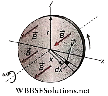
∴ Total induced emf between the centre and a point on the rim of the disc,
∴ \(e=\int_0^r \nu_B^{\prime} B d x=\int_0^r \omega x B d x=\frac{1}{2} \omega B r^2\)
⇒ \(\frac{1}{2} \times 20 \pi \times 10^{-2} \times(0.1)^2\)
∴ 0.00314 V = 3.14 mV
Examples of Applications of Electromagnetic Induction
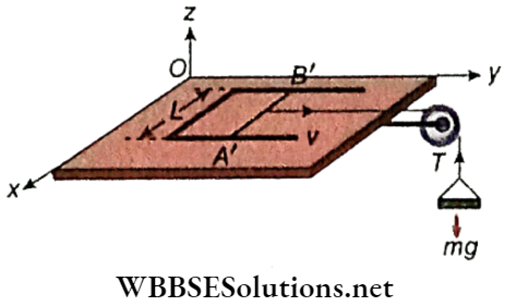
Example 3. A pair of parallel horizontal conduct invariable resistance shorted at one end Is fixed on a smooth table. The distance between the rails Is L. A massless conducting rod of resistance R can slide on the rails frictionlessly. The rod is tied to a massless string which passes over a pulley fixed to another edge of the table. A mass m, tied to the other end of the string, hangs vertically. A constant magnetic field B exists along the perpendicular to the plane of the table in an upward 1 direction. If the system Is released from rest, calculate
- The terminal velocity of the rod,
- The acceleration of the mass at the instant, when the velocity of the rod is half the terminal velocity.
Solution:
1. Let, rod A’B’ of length L and resistance R slide with a velocity v along the y-axis, while a constant magnetic field B exists along the z-direction.
Induced emf in the rod, e = BLv
The induced current flowing through the rod,
⇒ \(I=\frac{e}{R}=\frac{B L v}{R}\)
The direction of flow of the current through the rod A’B’ will be such that, it opposes the cause of generation of induced emf i.e., the motion of the rod along a positive y-axis. Thus the rod will experience force along the negative y-axis. The magnitude of the force is given by,
⇒ \(F=B I L=B \cdot \frac{B L v}{R} \cdot L=\frac{B^2 L^2 v}{R}\)
Let the rod move with acceleration, along the positive y-axis. Then from the equation of motion,
⇒ \(m a=m g-F=m g-\frac{B^2 L^2 v}{R} \quad \text { or, } a=g-\frac{B^2 L^2 v}{m R}\)
When the rod gets terminal velocity v0, then a = 0
∴ \(0=g-\frac{B^2 L^2 v_0}{m R}\)
∴ \(v_0=\frac{m g R}{B^2 L^2}\)
2. When the rod moves with velocity, \(v=\frac{1}{2} v_0\), then
⇒ \(v=\frac{m g R}{2 B^2 L^2}\)
Hence the acceleration of the mass at the instant
∴ \(a=g-\frac{B^2 L^2}{m R} \cdot \frac{m g R}{2 B^2 L^2}=g-0.5 g=0.5 g\)
Electromagnetic Induction And Alternating Current
Electromagnetic Induction Eddy Current
To enhance the effect of electromagnetic induction, in many cases, solid plates of soft iron or rods are used as the core of the armatures rotating in a magnetic field.
For example, in a dynamo, the armature rotating in the magnetic field is wound on a core of soft iron. Now, iron is a good conductor of electricity.
So electromagnetic induction takes place over the entire volume of the iron rotating in the magnetic field.
Many closed circuits or loops are formed locally within iron and induced current continues to flow in each loop.
Such current is known as eddy current Generally eddy current is produced whenever a conducting metal plate is in motion in a magnetic field.
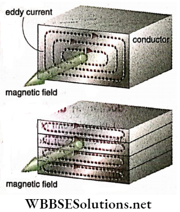
If there is a relative motion between a conducting metal piece and a magnetic field, an induced current is set up throughout the volume of the metal in different closed loops. This current is known as eddy current.
According to Lenz’s law, eddy current opposes the cause that produces it, i.e., it opposes the relative motion between the metallic conductor and the magnetic field.
Due to this opposition, heat is generated in the conductor. This wasteful thermal energy comes at the cost of useful energy.
To minimise the loss of energy in the form of heat due to eddy current the cores are not taken as a single piece but are made of many thin laminas ofconductors which are insulated from each other with suitable insulating materials.
By doing so, the flux linked with local eddy current circuits is reduced to a minimum, hence eddy current becomes quite weak and its heating effect is minimised.
On calculation, it is observed that if the number of lamina is n instead of a single one, the loss of energy due to eddy current will come down to \(\frac{1}{n}\) times.
On the other hand, eddy current in some cases can be applied in our favour. For example, the coil of a moving coil galvanometer when deflected in the magnetic field begins to oscillate around the equilibrium position.
It takes a long time to come to rest To get rid of this problem the coil is wound on a single soft iron core.
The eddy current thus produced in the core opposes the motion of the coil following Lenz’slaw. Thus, the coil will not oscillate for a long time after the current is cut off.
It will return to the equilibrium position quickly. Besides this, eddy current is employed usefully in induction motors, induction cookers, electric brakes, etc.
Electromagnetic Induction And Alternating Current
Electromagnetic Induction Inductance Of A Coil
Self Induction
When current flows through a coil, a magnetic field is generated around the coil. As a result, the coil becomes linked up with its magnetic flux.
This magnetic flux Increases or decreases with the increase or decrease of current. Hence, an electromagnetic induction takes place and an emf is induced in the coil.
This induced emf opposes the change in electric current through the coil. This phenomenon is known as self-induction.
Definition: An electromagnetic induction in a coil due to a change of current through itself is called self-induction.
The electric current generated due to self-induction flows in the direction opposite to the main current.
Self-Inductance: If current flows through a coil, the magnetic flux linked with the coil becomes directly proportional to the current passing through it. So, if the magnetic flux is <p for current I, then
Φ ∝ I or, Φ = LI →(1)
L is a constant which depends on its construction. It is called the self-inductance or coefficient of self-induction of the coil. If I = 1, then L = Φ.
Definition: For unit current flowing through a coil, the magnetic flux linked with it is called its self-inductance.
Again, we know that the emf induced in the coil, \(e=-\frac{d \phi}{d t}\)
So, using equation (1) we can write,
\(e=-L \frac{d I}{d t}\) → (2)
If \(\frac{d I}{d t}=1\), then e = L (considering the magnitude only). From this, the following alternative definition of self-inductance can be drawn:
If the rate of change of electric current in a coil with time is unity, the emf induced in the coil is called its self-inductance.
Unit Of Self-Inductance:
In SI: In this system, the unit of self-inductance is Henry (H). To define it, we can use either of the equations (1) or (2).
- If I = 1 A and 0 = 1 Wb, then L = 1 H.
- If \(\) and e = 1 V, then L = 1 H.
So, the self-inductance of a coil is 1 H if
- For n current of 1 A flowing through that coll, the magnetic flux linked with It is I Wb; or,
- For a change of 1 A current in 1 second through that coll, the emf induced In It Is 1 V.
Hence, from equation (1) we get
Wb = H.A → (3)
Again from equation (2) we get
⇒ \(V=H \cdot \frac{A}{s} \quad \text { or, } \frac{V}{A} \cdot s=H\)
∴ H = Ω.s → (4)
The unit of resistance R is Ω and the unit of self-inductance L is H. Hence from equation (4) we infer that the unit of \(\frac{L}{R}\) and the unit of time is the same.
In CG System: Putting \(\frac{d I}{d t}=1 \mathrm{emu} \cdot \mathrm{s}^{-1}\) and e = 1 emu of emf, we get, L = 1 emu of self-inductance. So, if the current is changed at the rate of 1 emu.s-1 and 1 emu electromotive force is induced in the coil, the self-inductance of that coil is 1 emu.
Relation between the CGS and SI units of self-inductance:
⇒ \(1 \mathrm{H}=\frac{1 \mathrm{~V}}{1 \mathrm{~A} \cdot \mathrm{s}^{-1}}=\frac{10^8 \mathrm{emu} \text { of potential difference }}{\frac{1}{10} \text { emu of current per second }}\)
= 109 emu of inductance
Non-inductive Coil: Self-induction creates disturbances in many electrical circuits. A coil of finite resistance but of zero self-inductance is often required. Such a coil is called a non-inductive coil.
A long insulated conducting wire is given a fold and then coiled up. The free ends of the coil are now on the same side. This kind of winding is called non-inductive winding.
Hence antiparallel currents flow through adjacent wires of any part of the coil. So, the resultant magnetic flux becomes zero. That means, in this coil, no electromagnetic induction takes place.
Effect Of Self-Induction On Electrical Circuit:
In the circuit, if the emf of battery B is E, the effective emf of the circuit due to self-induction [according to equation (2)] = \(E-L \frac{d I}{d t}\)
If the current is zero or a steady current flows through the circuit, \(\frac{d I}{d t}=0\); and in this case, self-induction does not affect the circuit.
On the other hand, self-induction affects a circuit when electric current changes with time in that circuit.
Thus, self-induction plays an important role in an AC circuit. In the case of a DC circuit, self-induction occurs only when the circuit is switched ‘on’ or ‘off.
Choke: A coil of high self-inductance and low resistance is commonly called a choke. If a choke is connected in series in an AC circuit, then due to its high self-inductance, the effective resistance of the circuit increases.
On the other hand, due to the low resistance of the coil, less heat is produced in the circuit. So, the function of a choke is to increase the effective resistance of the circuit lowering the dissipation of heat energy as much as possible.
Uses: In a tube light arrangement, a choke is usually connected in series.
Energy stored In the magnetic field of an inductor: We have induced emf in an inductor carrying a time-varying current i, \(e=-L \frac{d i}{d t}\), where L = self-inductance of the inductive coil.
To increase the current in the inductor against this opposing emf, some energy has to be spent on work. This external work will be stored in the magnetic field of the inductor as magnetic energy.
Power, i.e., rate of work done = ei = \(L i \frac{d i}{d t}\) (the negative sign is not taken in calculation of work done)
So, work done in time dt = ei dt = Lidi
Total work done to increase the current through the inductor from 0 to I,
⇒ \(W=L \int_0^I i d i=L \cdot\left[\frac{i^2}{2}\right]_0^I=\frac{1}{2} L I^2\)
This work done is stored as energy (EL) in the magnetic field of the inductor, i.e.,
∴ \(E_L=\frac{1}{2} L I^2\)
Mutual Induction
Let two coils, P and S, be kept very close to each other. Now if current is passed through them (say, P), a magnetic field is generated around it.
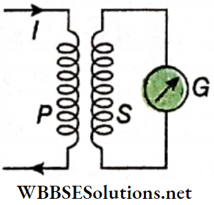
As a result, the second coil (S) gets linked with the magnetic flux generated by the first coil. If the current through P is increased or decreased concerning time.
The magnetic flux linked with an electromotive force induced in the coil S will also increase or decrease accordingly. Hence, an electromotive force is induced in the coil S.
This phenomenon is known as mutual induction. The first coil P is called the primary coil and the second coil S is called the secondary coil.
Definition: If current changes over time in a coil, the electromagnetic induction that occurs in an adjacent coil is called mutual induction.
Mutual Inductance: Mutual inductance is defined in a similar way as self-inductance. If the magnetic flux linked with the secondary coil is Φs for the current Ip in the primary coil then,
⇒ \(\phi_S \propto I_P \quad \text { or, } \phi_S=M I_P\) → (1)
Here, M is a constant, which depends on the geometry of the coils and the distance between them and is called mutual inductance or coefficient of mutual induction.
Naturally for Ip = 1, M = Φs
Definition: In the case of two adjacent coils, if one carries a unit current, then the magnetic flux linked with the other is called the mutual inductance between the two coils.
Again, induced emf in the secondary cop,
⇒ \(e=-\frac{d \phi_S}{d t}=-M \frac{d I_P}{d t}\) → (2)
If \(\frac{d I_p}{d t}=1\), then e = M [considering the magnitude only]
From this, the following, an alternative definition of mutual inductance is obtained.
In the case of two adjacent coils, if the rate of change of current concerning time in a coil is unity, the emf induced in the other coil is called the mutual inductance between the two coils.
Unit Of Mutual Inductance:
In SI: In this system, the unit of mutual inductance is Henry (H), exactly that of self-inductance L.
‘Mutual inductance between a pair of coils is 1 H’ means that,
- If the current passing through one coil is 1 A, the magnetic flux linked with the other becomes 1 Wb; or,
- If the current changes through one coil at the rate of 1 A per second, the emfinduced in the other becomes 1 V.
In the CGS system: If \(\frac{d I}{d t}=1\) emu of current per second and e = 1 emu of potential, then M = 1 emu of mutual inductance. So, in the case of two adjacent coils, if the current changes at the rate of 1 emu.s-1 in one coil and as a result if 1 emu of emf is induced in the other coil, the mutual inductance between the coils is said to be 1 emu.
Discussions:
Interchange of two colls: The second coil can be used as the primary coil and the first as the secondary. In that case, due to: a change in current in the second coil, electromagnetic induction will take place in the first coil, and the value of mutual, inductance (M) will remain unchanged.
Relation between self-inductance, and mutual inductance: If the self-inductances of the two coils are, L1 and L2, the mutual inductance becomes
⇒ \(M=k \sqrt{L_1 L_2}\) (3)
Here, k is a constant whose value is 1 or less than 1. If the magnetic flux of one coil is linked completely with the other; k≈1. Thus,
∴ \(M \approx \sqrt{L_1 L_2}\)
Electromagnetic Induction And Alternating Current
Electromagnetic Induction Inductance Of A Solenoid
Self-inductance of a solenoid: Let the length of the solenoid = l, area of its circular cross-section = A.
So, if several turns are N, then the number of turns per unit length (n) = \(\frac{N}{l}\).
If current I flow through the solenoid, then the magnetic field thus generated inside it is
B = μ0nI, where μ0 = magnetic permeability of vacuum or air.
So, the magnetic flux linked with each, turn of the solenoid,
⇒ \(B A=\mu_0 n A I=\frac{\mu_0 N A}{l} \cdot I\)
Hence; the magnetic flux linked with JV turns,
⇒ \(\phi=N B A=\frac{\mu_0 N^2 A}{l} \cdot I\)
If the self-inductance of the solenoid is L then, Φ = LI
∴ \(L=\frac{\phi}{I}=\frac{\mu_0 N^2 A}{l}\)
For any other medium of magnetic permeability p inside the solenoid, \(L=\frac{\mu N^2 A}{l}\).
Mutual Inductance Of Two Inseparable Solenoids:
PP’ and SS’ are primary and secondary solenoids respectively. They arpÿound over each other on a length. The cross-sectional area of each of them = A
Number of turns in length l in PP’ = N1 and that in SS’ = N2.
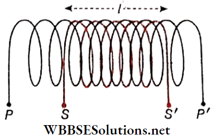
Therefore, the number of turns per unit length of PP’.
⇒ \(n_1=\frac{N_1}{l}\)
If I1 current flows through the primary coil PP’, the magnetic field thus developed inside it,
⇒ \(B_1=\mu_0 n_1 I_1=\frac{\mu_0 N_1}{l} I_1\)
[μ0 = magnetic permeability of vacuum or air]
As the solenoids are closely wound on each other, the magnetic flux linked in each turn of the secondary coil = B1A and hence the magnetic flux linked with N2 turns,
⇒ \(\phi_2=N_2 B_1 A=\frac{\mu_0 N_1 N_2 A}{l} \cdot I_1\)
If the mutual, inductance of the solenoid is M then,
⇒ \(\phi_2=M I_1\)
So, \(M=\frac{\mu_0 N_1 N_2 A}{l}\) → (2)
For any other medium used as the core, M = \(\frac{\mu N_1 N_2 A}{l}\), where mu = magnetic permeability of that medium.
In the present context, self-inductances of the coils are
⇒ \(L_1=\frac{\mu_0 N_1^2 A}{l} \text { and } L_2=\frac{\mu_0 N_2^2 A}{l}\)
So, \(L_1 L_2=\left(\frac{\mu_0 A}{l}\right)^2 N_1^2 N_2^2=\left(\frac{\mu_0 N_1 N_2 A}{l}\right)^2=M^2\)
i.e., \(M=\sqrt{L_1 L_2}\)
Comparing this equation with equation (3). we get, k = 1. This is the maximum value of k.
Energy Density In The Magnetic Field Of A Solenoid:
Length of a solenoid = l, cross-sectional area = A
So, its volume = l A.
If N be the total turns ui the solenoid, the number of turns per unit length of it, \(n=\frac{N}{l}\)
If I current flows through the solenoid, the magnetic field thus develops along its axis,
⇒ \(B=\mu_0 n I=\frac{\mu_0 N I}{l} \quad \text { or, } I=\frac{B l}{\mu_0 N}\)
But, self-inductance of the solenoid,
⇒ \(L=\frac{\mu_0 N^2 A}{l}\)
So, the stored energy in its magnetic field,
⇒ \(U=\frac{1}{2} L I^2=\frac{1}{2} \frac{\mu_0 N^2 A}{l}\left(\frac{B l}{\mu_0 N}\right)^2=\frac{1}{2 \mu_0} B^2 L A\)
So, the energy stored per unit volume,
⇒ \(u=\frac{U}{L A}\)
i,e. \(u=\frac{1}{2 \mu_0} B^2\) → (3)
This u is the energy density in the magnetic field. For any other medium, instead of air or vacuum,
⇒ \(u=\frac{1}{2 \mu} B^2\)
Though equation (3) has been established for the magnetic field inside a solenoid, it is a general equation for any magnetic field because the relation is independent of the geometrical features of the inductor.
To find the energy density at a point in any magnetic field the above equation may be applied. Unit of energy density = J.m3 and its dimension = \(\frac{M L^2 T^{-2}}{L^3}=M L^{-1} T^{-2}\)
Electromagnetic Induction And Alternating Current Electromagnetic Induction Inductance Of A Solenoid Numerical Examples
Example 1. The mutual inductance between two adjacent coils is 1.5 H. If the current in the primary coil changes from 0 to 20 A in 0.05 s, determine the average emf. induced in the secondary coil. If the number of turns in the secondary coll is 800, what change in flux will be, observed in it?
Solution:
The average value of induced emf,
⇒ \(e=-M \frac{\Delta I}{\Delta t}=-1.5 \times \frac{(20-0)}{0.05} \stackrel{211}{=}-\frac{1.5 \times 20}{0.05}=-600 \mathrm{~V}\)
Hence, the magnitude of the induced emf = 600 V.
Again, from the relation Φ = MI, we get,
change in flux, ΔΦ = M. ΔI = 1.5 x (20 – 0) = 30 Wb
Example 2. When the current in a coil changes from + 2 A to -2 A in 0.05 s, an emf of 8 V is induced in the coil. Determine the self-inductance of the coil
Solution:
We know that, \(e=-L \frac{\Delta I}{\Delta t}\)
Self-inductance of the coil, L = \(L=-\frac{e \Delta t}{\Delta I}=\frac{8 \times 0.05}{-2-(+2)}=0.1 \mathrm{H}\)
Conceptual Questions on Eddy Currents and Their Applications
Example 3. The mutual inductance of two coils is 0.005H, ac in the primary coil, I = I0 sin ωt, where I0 = 10A and ω = 100π rad/s. What is the maximum emf in the secondary coil?
Solution:
ac in the primary coil, I = I0 sin ωt
∴ \(\frac{d I}{d t}=\omega I_0 \cos \omega t\)
So, \(e_2=-M \frac{d I}{d t}\) [here M = mutual inductance]
= -M ωI0 cos ωt
So the maximum emf in the secondary coil
= MωI0 = 0.005 x 100π X 10 = 15.7V
Example 4. If a rate of change of current of 2 A.s-1 induces an emf of 10 mV in a solenoid, what is the self-inductance of the solenoid?
Solution:
∴ \(e=-L \frac{d I}{d \hbar} \quad \text { or, } L=\frac{|e|}{\frac{d I}{d t}}=\frac{10 \times 10^{-3} V}{2 \mathrm{~A} \cdot \mathrm{s}^{-1}}=5 \mathrm{mH}\)
Example 5. The resistance of a coil is 10Ω and its self-inductance is 5H. Find the energy stored when it is connected to a 100V battery.
Solution:
Curreht in circuit, \(I=\frac{V}{R}=\frac{100}{10}=10 \mathrm{~A}\)
Stored energy in the inductor = \(\frac{1}{2} L I^2=\frac{1}{2} \times 5 \times(10)^2=250 \mathrm{~J}\)
Example 6. The self-inductance of an air core solenoid increases from 0.01 mH to 10 mH when an iron core is introduced into it. What is the relative magnetic permeability of iron?
Solution:
Self-inductance is proportional to the permeability of the core. So, we get
⇒ \(\frac{L}{L_0}=\frac{\mu}{\mu_0}=\mu_r \quad \text { or }, \mu_r=\frac{L}{L_0}=\frac{10}{0.01}\)
∴ \(\mu_r=1000\)
Hence relative magnetic permeability of iron is 1000.
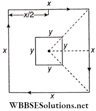
Example 7. A small square loop of wire of side y is placed Inside a large square loop of side x (x»y). The loops are coplanar and their centres coincide. Find the mutual inductance of the system.
Solution:
Let I be the current flowing through a square loop of side L.
The magnetic field at the centre of the loop, B = 4B1
[where B1 is the magnetic field at the centre of the loop due to one of its sides]
Now, for the large square loop, L = x
∴ \(B_1=\frac{\mu_0}{4 \pi} \cdot \frac{I}{\frac{x}{2}}\left(\sin 45^{\circ}+\sin 45^{\circ}\right)\) [∵ V distance of the centre from each side of the large loop = \(\frac{x}{2}\)]
⇒ \(=\frac{\mu_0}{2 \pi} \cdot \frac{I}{x}\left(\frac{1}{\sqrt{2}}+\frac{1}{\sqrt{2}}\right)=\frac{\mu_0 I}{\sqrt{2} \pi x}\)
∴ \(B=\frac{4 \mu_0 I}{\sqrt{2} \pi x}=\frac{2 \sqrt{2} \mu_0 I}{\pi x}\)
Now, magnetic flux linked with the small square loop,
Φ =B x area of the small square loop
\(B \times y^2=\frac{2 \sqrt{2} \mu_0 I y^2}{\pi x}\) → (1)
If M be the mutual inductance between the two loops, then
Φ = MI → (2)
From equations (1) and (2), \(M=\frac{2 \sqrt{2} \mu_0 y^2}{\pi x}\)
Real-Life Scenarios in Electromagnetic Induction Experiments
Example 8. Cross sectional area, of a solenoid is 10 cm2. Haif of its cross section is filled with iron (μr = 450) and the remaining half with air ( μr = 1 ). Calculate the self-inductance of the solenoid fits length is 2m and the number of turns is 3000.
Solution:
If the α1 part of the cross-section of the solenoid is filled with a substance of relative permeability μr1 and the remaining part of the cross-section α2 with another substance of relative permeability μr2 then self-inductance of the s inside is,
⇒ \(L=\frac{\mu_0 n^2 A}{l}\left(\mu_{r_1} \alpha_1+\mu_{r_2} \alpha_2\right)\)
Here μ0 = 4π x 10-7 H/m; number of Pirns, n = 3000; length of solenoid, l = 2m; area of cross section A = 10cm2 = 0.001m2; α1 = 0.5 and α1 = 0.5.
∴ Self-inductance of the solenoid,
⇒ \(L=\frac{4 \pi \times 10^{-7} \times(3000)^2 \times 0.001}{2}(1 \times 0.5+450 \times 0.5) \mathrm{H}\)
⇒ 2π x 9 x 10-4 x (0.5 + 225) H
= 1.27H (approx.)
Electromagnetic Induction And Alternating Current
Electromagnetic Induction Very Short Questions And Answers
Question 1. What is the unit of magnetic induction or magnetic flux density in SI?
Answer: Wb.m-2 or T
Question 2. What is the relation of the magnetic field vector 5 with magnetic induction and magnetic flux density?
Answer: They are the spare physical quantity.
Question 3. Induced emf is direct propohiotfÿ’tti the rate of change with time of magnetic _____ linked with a coil.
Answer: Flux
Question 4. In the case of electromagnetic induction, the _______ always opposes the cause of its generation.
Answer: Current
Question 5. With the help of Fleming’s _______ rule, the direction of induced current in a straight conductor in motion can be determined.
Answer: Right-hand
Question 6. What is the relation between the units: tesla and Weber?
Answer: \(\mathrm{IT}=\frac{1 \mathrm{wb}}{1 \mathrm{~m}^2}\)
Question 7. What is the relation between the units: Weber and Volt?
Answer: 1 Wb = 1 V.1 s
Question 8. Which of the conservation laws would not hold if Lenz’s law was incorrect?
Answer: The law of conservation of energy
Question 9. The self-inductance of a coil is 1H. If 1A current passes through it, what will be the magnetic flux linked with the coil?
Answer: 1 Wb
Question 10. What is the relation between the units: weber and ampere?
Answer: 1 Wb = 1A.1H
Question 11. What is the relation between the units of self-inductance and mutual inductance?
Answer: They have the same unit
Question 12. The self-inductance of an air core inductor increases from 0.01 mH to 10 mH on introducing an iron core into it. What is the relative permeability of the core used?
Answer: 1000
Electromagnetic Induction And Alternating Current
Electromagnetic Induction Synopsis
if there is a relative motion between a magnetic field and a conductor, the electromotive force (emf) generated in that conductor is called induced emf.
- If there is a relative motion between a magnetic field and a closed conductor, the current generated through that conductor is called induced current.
- The number of lines of induction passing normally through the unit area surrounding a print inside a substance is called the magnetic induction (\vec{B}) of that point.
- The number of lines of induction that crosses normally any surface placed in a magnetic field is called the magnetic flux (Φ) linked with that surface.
Faraday’s laws of electromagnetic induction:
- First law: Whenever the magnetic flux linked with a coil changes with time, an emf is induced in the coil. The induced EMF lasts as long as the change in magnetic flux linked with the coil continues.
- Second law: The strength of the induced emf is directly proportional to the time rate of change of magnetic flux linked with a coil.
- Lenz’s law: In the case of electromagnetic induction the direction of induced emf is such that, it always opposes the cause of the generation of current in the circuit.
- The change of magnetic flux linked with a conducting coil in unit time, for which unit electromotive force is induced in the coil, is taken as the unit of magnetic flux.
Units of magnetic flux:
Units of magnetic induction:
- An electromagnetic induction that takes place in a coll due to a change of current through itself is called self-induction. The electric current generated due to self-induction flows in the direction opposite to the main current.
- The magnetic flux linked with a coil for unit current flowing through the coil is called its self-inductance.
- A coil having finite resistance but zero self-inductance is called a non-inductive coil.
- A coil having a high self-inductance but low resistance is called a choke.
- The phenomenon of production (induction) of emf in a coil due to a change in current with time in a neighbouring coil is called mutual induction.
- The magnetic flux linked with a coil due to the flow of unit current through a neighbouring coil is called the mutual inductance between the two colls.
- Units of self-inductance and mutual inductance: Henry (H), in SI.
- If there is a relative motion between a conducting metal piece and a magnetic field, an induced current is set up throughout the volume of the metal in different closed loops. This current is known as eddy current.
To minimise the loss of energy in the form of heat due to eddy current, the core is not taken as a single piece of conductor but is made of many thin laminas of conductors which are insulated from each other with suitable insulating materials.
- Magnetic flux linked with surface \(\vec{A}\),
⇒ \(\phi=B A \cos \theta=\vec{B} \cdot \vec{A}\)
[where \(\vec{B}\) = magnetic induction, 6 = angle between \(\vec{B}\) and \(\vec{A}\)]
The magnetic flux through a finite surface S,
∴ \(\phi=\int_S \vec{B} \cdot d \vec{A}\)
- According to Faraday’s second law,
induced emf, \(e \propto \frac{d \phi}{d t}\). In combination with Lenz’s law and the chosen units of 0, it becomes, \(e=-\frac{d \phi}{d t}\).
- 1 Wb = 108 Mx, IT = 104G, Wb = V.s
- Induced emf in a straight conductor moving in a magnetic field, e = Blvsind [where B = magnetic flux density, l = length of the conductor, v = velocity of the conductor and 0 = angle between \(\vec{B}\) and \(\vec{v}\))
- The emf induced between the two ends of a conductor rotating in a uniform magnetic field,
∴ \(e=\frac{1}{2} B \omega L^2\)
[where L = length of the conductor, co = steady angular velocity]
- For current I, if the magnetic flux is <p, then
Φ ∝ I = 1 or, 0 = LI (L = self-inductance of the coil]
The equation \(e=-\frac{d \phi}{d t} \text { gives, } e=-L \frac{d I}{d t}\)
∴ Wb = H.A, H = n .s
or 1 H = 109 emu of Inductance
- If the flux linked with the secondary coll is 0 for current I in the primary coil, then
Φ ∝ I or, Φ = MI {M = mutual inductance]
- If the self-inductances of two coils are L1 and L2, mutual inductance, \(M=k \sqrt{L_1 L_2}\) where k is a constant whose value is 1 or less.
- Energy stored in the magnetic field of a conducting coil of self-inductance L due to current I flowing through it = \(\frac{1}{2} L I^2\).
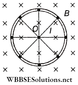
A conducting wheel is rotating in a uniform magnetic field with angular velocity co. The length of each spoke is l. If there are n number of spokes in the wheel.
Then total electromotive force between the centre and any point situated on the circumference of the wheel, \(e=\frac{1}{2} B \omega l^2\). Here, the total emf does not depend on the number of spokes.
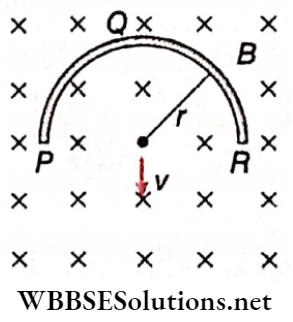
- A thin semicircular conducting ring (PQR) of radius r is falling with its plane vertical in a horizontal magnetic field B, as shown. If the speed of the ring is v, the value of the induced emf between the two ends of the semicircular ring, c = B x (2r) x v.
- Here, the induced emf depends upon the distance between the two ends of the conductor, not on the shape of the conductor.
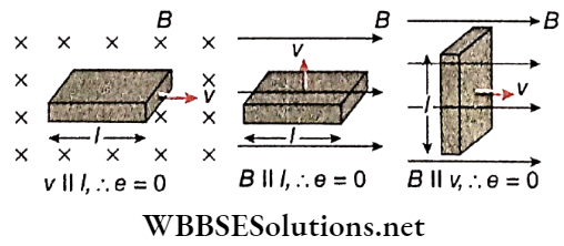
- If any two vectors among the three vectors \(\vec{B}, \vec{v} \text { and } \vec{l}\) are parallel, then the motion emf induced in the conductor, e = 0.
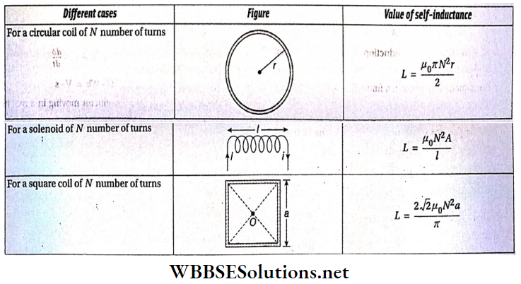
- Values of self-inductance in some special cases:
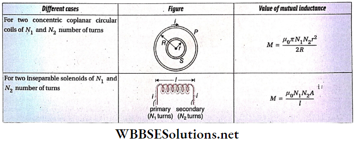
- Values Of Mutual Inductance In Some Special Cases:
Electromagnetic Induction And Alternating Current
Electromagnetic Induction Assertion Reason Type Questions And Answers
Direction: These questions have statement 1 and statement 2 Of the four choices given below, choose the one that best describes the two statements.
- Statement 1 is true, statement 2 Is true; statement 2 is a correct explanation for statement 1
- Statement 1 is true, Statement 2 Is true) statement 2 is not a correct explanation for statement 1
- Statement 1 is true, statement 2 is false
- Statement 1 is false, statement 2 Is true
Question 1. Statement 1: Induced emf in a conductor is proportional to the time rate of change of associated magnetic flux.
Statement 2: In the case of electromagnetic induction transfer of energy takes place in a manner energy is conserved.
Answer: 2. Statement 1 is true, Statement 2 Is true) statement 2 is not a correct explanation for statement 1
Question 2. Statement 1: The north pole of a.bar, magnet is moving towards a closed circular coil along its axis. As a result, the direction of induced currently the front face of the coil will be clockwise.
Statement 2: Any incident connected with electromagnetic induction obeys Lenz’s law.
Answer: 4. Statement 1 is false, statement 2 Is true
Question 3. Statement 1: The charge passing through a coil in time At is \(\frac{\Delta \phi}{R}\), where R is the resistance of the coil and ΔΦ is the change in flux linked with the coil in time Δt:
Statement 2: The induced emf in a conductor \(e \propto \frac{d \phi}{d t}\), at \(\frac{d \phi}{d t}\) where is the time rate of change of flux linked with the conductor.
Answer: 1. Statement 1 is true, statement 2 Is true; statement 2 is a correct explanation for statement 1
Question 4. Statement 1: A closed solenoid is placed in an external magnetic field. Both the magnetic field and axis of the solenoid are directed along the z-axis. No electromotive force will be induced if the solenoid is rotated along its axis.
Statement 2: Electromagnetic induction in a conducting coil takes place only when the magnetic flux linked with the coil changes with time.
Answer: 1. Statement 1 is true, statement 2 Is true; statement 2 is a correct explanation for statement 1
Question 5. Statement 1: Self-inductance of a solenoid having 1000 turns is l00 mH if the associated magnetic flux linked with each turn is 10-3 Wb for a current of 1 A passing through the solenoid.
Statement 2: The self-inductance L of a coil is defined as Φ = LI when <p is the magnetic flux linked with the coil for a current I through it.
Answer: 4. Statement 1 is false, statement 2 Is true
Question 6. Statement 1: When two coils are wound on each other, the mutual induction between the coils is maximum.
Statement 2: Mutual induction does not depend on the orientation of the coils.
Answer: 3. Statement 1 is true, statement 2 is false
Question 7. Statement 1: When the number of turns of a coil. doubled, the coefficient of self-inductance of the coil becomes 4 times.
Statement 2: Self-inductance oc (number of turns)2
Answer: 1. Statement 1 is true, statement 2 Is true; statement 2 is a correct explanation for statement 1
Electromagnetic Induction And Alternating Current
Electromagnetic Induction Match The Following
Question 1. Some physical quantities are given in column 1 while their units are given in column 2.
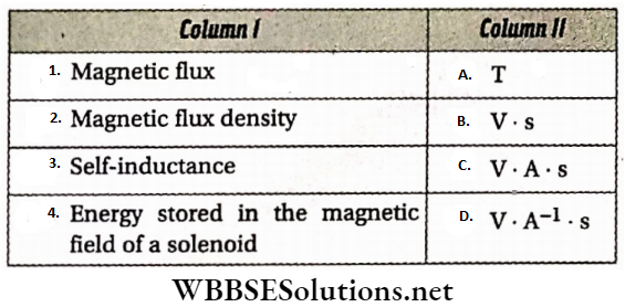
Answer: 1-B, 2-A, 3-D, 4-C.
Question 2. Column 1 gives the value of self-inductance (L) and the current (I) through some coils. Column 2 gives the energy stored in them.
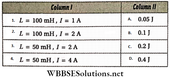
Answer: 1-A, 2-C, 3-B, 4-D
Question 3. Column 1 describes,s some solenoids kept in the air while column 2 gives, their self-inductance. Magnetic permeability of air = 4π x 10-7 H.m-1.
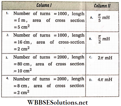
Answer: 1-A, 2-B, 3-C, 4-D
Electromagnetic Induction And Alternating Current
Electromagnetic Induction Comprehension Types
Read The Following Passage Carefully And Answer The Questions At The End Of It.
If the current through a solenoid changes with time electromagnetic induction takes place in the solenoid. This is known as self-induction, In general, for a current I, the induced emf in the coil is \(e=-L \frac{d I}{d t}\).
L is the self-inductance of the solenoid. On the other hand, such a change in the current in a solenoid can produce electromagnetic induction, in another adjacent solenoid. The induced emf in the other solenoid \(e=-M \frac{d I}{d t}\), M is called the mutual inductance of the solenoids.
If L1 and L1 are the self-inductance of the adjacent coils then their mutual inductance \(M=k \sqrt{L_1 L_2}\). If the magnetic flux produced by the current in one coil is linked with the other coil then k = 1.
Question 1. Unit of self-inductance L is Henry (H). Its relation with other known units is
- V.s
- A.s-1
- Ω .s
- Ω .s-1
Answer: 3. Ω .s
Question 2. The self-inductance (in H) of a coil when the Induced emf is 5.0μV for a change of 1 mA.s-1 in current through it, is
- 50
- 5
- 0.5
- 0.05
Answer: 4. 0.05
Question 3. If the induced emf in a coil linked with the coil in question (2) is 20μV, the mutual inductance (in H) of die two coils is
- 0.002
- 0.02
- 0.2
- 2
Answer: 2. 0.02
Question 4. Self-inductance (in H) of the coil in question (3) is
- 0.1
- 0.08
- 0.01
- 0.008
Answer: 4. 0.008
Question 5. The negative sign in the expression of induced emf is explained by
- Faraday’s first law
- Faraday’s second law
- Law of conservation of energy
- Law of conservation of charge
Answer: 3. Law of conservation of energy
Electromagnetic Induction And Alternating Current
Electromagnetic Induction Integer Answer Type
In this type, the answer to each of the questions Is a single-digit integer ranging from 0 to 9.
Question 1. The current through a coil of self-inductance 500 mH is 4 A. What amount of magnetic energy (in J) is stored in its magnetic field?
Answer: 4
Question 2. A straight conductor of length 50 cm is moving with a velocity of 5 m.s-1 in a magnetic field of strength 2T in a direction perpendicular to the field. What is die emf(in V) induced between the two ends of the conductor?
Answer: 5
Question 3. The magnetic flux Φ (in Wb) linked with a 100H coil changes with time t (in s) according to the relation Φ = 8t2 – 2t + 1. What is the value of induced current (in A) in the coil at t = 2 s?
Answer: 3
Question 4. A straight conductor of length 10 cm Is rotating In a vortical plane with one of Its ends fixed. The angular velocity Is 10 rad.s-1. What is the value of one (In μV ) Induced between the two ends of the conductor If the horizontal component of earth’s magnetic field at the place Is 10-4 T?
Answer: 5
Question 5. A circular wire loop of radius is placed In the xy-plane centred at the origin 0. A square loop of side a (\(a \ll R\)) having two turns is placed with its centre at z = √3R along the axis of the circular wire loop, as shown. The plane of the square loop makes an angle of 45° concerning the z-axis. If the mutual Inductance between the loops is given by \(\frac{\mu_0 a^2}{2^{p / 2} R}\), then what is the value of p?
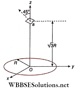
Answer: 7
Question 6. Find the change in magnetic flux (in Wb )in an inductor of 10H in which the emf induced is 300 V in 10-2 s.
Answer: 3
Question 7. An average induced emf of 0.20 V appears in a coil when the current is changed from 5A in one direction to 5A in the opposite direction in 0.20 s. Find the self-inductance of the coil in mH.
Answer: 4