WBCHSE Class 12 Physics Notes For Diffraction And Polarisation

Optics

Diffraction And Polarisation Of Light

Diffraction And Polarisation Of Light Definition:

Light rays, while passing round the edges of an A obstacle or aperture, instead of traveling in a straight line, bend to some extent. This phenomenon is known as the diffraction of light.

We know from our daily experience that sound wave bends while passing round the edges of an obstacle or spreads in all directions while passing through a slit or aperture. The same thing happens with light waves. A thin tin sheet placed in sunlight casts its shadow on a wall. Sunrays can be treated as parallel rays and according to geometrical optics, they travel in a straight line. So, a sharp shadow of the thin tin sheet should be observed on the wall.

But if the shadow is examined carefully, it will be seen that the edges are not very distinct. The direction of the light wave changes while passing through the edges of an obstacle or through an aperture. This is called ‘diffraction’ oflight

Read and Learn More Class 12 Physics Notes

In point of In a blade, formed by diffraction monochromatic pattern, mm formed just outside the shadow of the blade, is shown in an enlarged form. The shadow of the side of the blade is not very distinct. In diffraction due to slit or aperture, the deviation of the propagation of the wave depends on its wavelength and on the size of the slit or aperture

Comparison of diffraction Of light with diffraction of sound

The wavelength of an audible sound is sufficiently long (from 1.6 cm to 16 m). Even if there is a big hole in the line of propagation of the wave, the wave deviates considerably while passing through it. On the other hand, the wavelength of visible light is very small, 4000 A° -8000 A°.

Even a very fine slit, like the eye of a needle, is large enough in comparison to the wavelength oflight For a light wave, while passing through a slit large enough in comparison to its wavelength, there is no noticeable change in the direction of light, i.e., diffraction oflight isin distinguishable

Class 12 Physics Unit 6 Optics Chapter 7 Diffraction And Polarisation Of Light Comparision Of Diffraction Of Light With Diffraction

Now for the same wavelength oflight, as the aperture is gradually made finer, the diffraction of light becomes more distinct. On the other hand, a distinct diffraction can also be made to occur by increasing the wavelength oflight used, so that the slit can now be comparable in size with the wavelength of light .

Some Special Conclusions: Observing the phenomenon of diffraction of light

The following conclusions can be drawn:

  • Like other waves, light also spreads like a wave
  • If the size of the apertures is much larger than the wavelength of light, diffraction of light is not easily detectable. In
  • In that case,  can be said that light travels in a straight line. In the case of a very fine aperture, when light hends from its straight path, we come to know of the limitations of geometrical optics. That is why, the rectilinear behavior of light according to geometrical optics is actually an approximate behavior.
  • When the edges of the obstacle or aperture are sharp, diffraction is more distinctly detectable.
  • Diffraction validates the wave theory of light, but it does not give any information about the nature of light waves (whether it is longitudinal or transverse).
  • As the wavelengths are long, sound waves and radio waves are diffracted more prominently than other kind of waves.

Optics

Diffraction And Polarisation Of Light Comparison Between Interference And Diffraction Of Light

Similarity: Both interference and diffraction of light take place due to the superposition of waves. Diffraction fringes are formed mainly due to the interference of waves.

Dissimilarity: There are some basic differences between interference and diffraction of light. The differences are as follows

Difference Between Interference And Diffraction

Class 12 Physics Unit 6 Optics Chapter 7 Diffraction And Polarisation Of Light Difference Between Interference And Diffraction

Optics

Diffraction And Polarisation Of Light Classification Of Diffraction

The phenomena of diffraction oflight can be classified mainly into two classes

  1. Fresnel diffraction and
  2. Fraunhofer diffraction.

1. Fresnel diffraction

  • The diffraction, where both the source of light and the screen, are at finite distances from the obstacle or the aperture is called Fresnel diffraction.
  • In this diffraction, wavefronts incident on screen are either spherical or cylindrical.
  • Obstacles with sharp edges, narrow slits, thin wires, small circular obstacles or holes etc. can produce Fresnel diffraction.

2. Fraunhofer diffraction

  • The diffraction, where the source of light and the screen are virtually at an infinite distance, is called Fraunhofer diffraction.
  • In this case, the incident wavefront is a plane. Single slit, double slit, diffraction grating etc. produce Fraunhofer diffraction

Optics

Diffraction And Polarisation Of Light Fraunhofer Diffraction By Single Slit

Experimental arrangement

In this experiment of light from a monochromatic light source, Is made to a convex lens L1, through a narrow silt S. The slit S is held at e focus of the lens Lx. Hence, rays retracted from lens L1 parallel.

Classification-of-Diffraction-Phenomena-Fraunhofer-Diffraction-By-Single-Slit-1

This parallel beam of monochromatic light is incident normally on the slit AB placed perpendicular to the plane of the paper. The ray is now focussed by a convex lens I1 on a screen MN, where we observe diffraction fringes.  Instead of the screen, if the diffraction pattern is observed by an objective, the tire pattern will be observed in its focal plane

Class 12 Physics Unit 6 Optics Chapter 7 Diffraction And Polarisation Of Light Focal Plane

 Fraunhofer Diffraction By Single Slit Explanation

According to geometrical optics, light rays merging out from the slit AB, if focussed by the lens L2, should produce a sharp image of the slit, at point O of the screen. But actually, this does not happen.

This is because light is passing through AB, and does not propagate in straight lines. Getting diffracted by AB, the light rays spread upwards of point A id downwards of point B. So with the formation of a sharp Image of the slit O, alternate bright ml dark diffraction fringes are produced on both sides of O

Central of principle maximum

Is the midpoint of the silt AB. CO Is the principal axis, the livery point of the plane wavefront, which Is an Incident on the slit, and Is of tho name phase. All wavelets originating from those points and proceeding parallel to CO are focussed by L2 at O. Since those wavelets have no path difference, they are In the same phase. So, they make constructive Interference, and point O appears very bright. O is called principal or control maximum. Simplified form of

Class 12 Physics Unit 6 Optics Chapter 7 Diffraction And Polarisation Of Light Central Or Principle Maximum

Conditions for the formation of minima and secondary maxima

Suppose, some wavelets after being diffracted through an angle  are focussed at Ox by the lens L2

Now, the condition for the formation of constructive or destructive interference at the point Ox depends on the path difference of the wavelets originating from A and B. From A, a perpendicular AP is drawn on BOx.

So the path difference between the wavelets emergent from points A and B =BP. Now, BP =AB sin ∠BAP = a sin θ

[where, AB = a- width of the slit]

1. For minima:

To obtain the condition for minima being formed at O1, slit AB is notionally divided into halves, AC and CB, i.e., AC = CB = \(\frac{a}{2}\)

Let the wavelength of incident monochromatic light = λ. If the path difference between two wavelets, originating from points A and C be  \(\frac{\lambda}{2}\)  they would cause destructive interference.

S°, the condition of formation of first minima on both sides of O for diffracting angle θ1 is,

⇒ \(\frac{a}{2} \sin \theta_1=\frac{\lambda}{2} \quad \text { or, } a \sin \theta_1=\lambda\)

Or, \(\sin \theta_1=\frac{\lambda}{a}\) …………………………… (1)

In general, the condition for the formation of n th minimum on both sides of O, for diffracting angle θn is, a side = nλ …………………………… (2)

Putting n = ±1, ±2, ±3,………….  in equation (2), we would get simultaneously, first, second, third etc. minima on either side of the principal maximum. Here, ± sign is used to indicate diffractions on either side of the central line.

2. For secondary maxima:

If the path difference of the wavelets emitted from A and B, BP = \(\frac{3 \lambda}{2}, \frac{5 \lambda}{2}, \cdots(2 n+1) \frac{\lambda}{2}\) then at points O2, O4, etc. they would produce first, second, etc. maxima. At these points, the two waves superpose in the same phase. These are called secondary maxima. If ‘ is the corresponding angle of diffraction for the nth secondary maximum, then

⇒ \(a \sin \theta_n^{\prime}=(2 n+1) \frac{\lambda}{2}\) ………………..(3)

[where, n = ±1, ±2, ±3……. etc.]

It is to be noted that the intensity of the secondary maxima gradually decreases

The linear distance of the nth minimum from the central maximum

Generally, the wavelength of visible light (for example, A = 5 × 10⁻⁷m) is much lower than the width of the slit (for example, a = 10-4m ). For such values of θ, sin θ ≈θ. With this approximation, equation (2) becomes

⇒ \(\theta_n=\frac{n \lambda}{a}\) …………………………(4)

Let the distance from principal maximum point 0 to n th minimum point On, OOn = xn and distance from screen to slit =D

As the value of θn is very small,  \(\theta_n=\frac{x_n}{D}\)

Putting the value of θn in equation (4) we get

⇒ \(a \cdot \frac{x_n}{D}=n \lambda \quad \text { or, } x_n=\frac{n \lambda D}{a}\) ………. (5)

Putting n = ±1,±2, ±3-” etc. in equation (5), linear distances of various minima from central maximum are obtained

Width of central maximum

The angle between the first minima on either side of the central maximum is called the angular width of the central maximum.

According to equation (4), the angular spread of the central maximum on either side is

⇒ \(\theta=\frac{\lambda}{a}\)

Angular width of central maximum,

⇒ \(2 \theta=\frac{2 \lambda}{a}\) ……………………. (6)

Therefore, linear width of central maximum \(=D \cdot 2 \theta=\frac{2 D \lambda}{a}\) where D = distance of slit from the screen. If lens L2 is located very close to the slit AB, or if the screen MN is located far away from lens L2 > then D ≈the focal length of the lens (f).

In that case, linear width central maximum point In general, the condition for the formation of n th minimum on = \(\frac{2 f \lambda}{a}\)

Optics

Diffraction And Polarisation Of Light Resolving Power Of Optical Instruments

Two types of resolving power are relevant for different optical instruments: O Spatial resolving power and Q Spectral resolving power.

Spatial or angular resolving power

Our eye is an optical instrument. If two point objects (or their images) are very close to each other, our eyes may not see them as separate objects. They seem to be the same object or the same image. It can be verified by a simple experiment.

Let a white paper be fixed on a wall in front of us. On the paper black parallel lines are drawn at 2 mm distance apart. When we stand very close to the wall, we can see all the parallel lines. When we gradually move away from the wall, the angle formed by any two lines at our eye gets diminished and at one point it seems that die lines have merged with each other i.e., the lines can no longer be identified separately.

It can be inferred that whether two objects placed side by side can be differentiated, depends on the angle formed by the two objects at our eyes. It has been established through experiments that if the angle becomes less than 1 minute or \(\frac{1}{60}\) degree, eyes will not be able to see two objects separately.

This angle is called the angular limit of the resolution of our eyes. This means our eyes, as well as optical instrument, has their own limit of

Resolving images of two different objects located very near to each other:

  1. Limit of Resolution: The limit of Resolution is the smallest linear distance or the angular separation between two objects that can be directly seen through an optical instrument, is called the spatial limit of resolution of that instrument.
  2. Resolving power: The power or ability of an instrument to produce distinct separate images of two close objects, is called the spatial resolving power of the instrument.

Spatial resolving power is measured by the reciprocal of the limit of resolution. If Δx or is the linear or angular limit, then the resolving power would be \(\frac{1}{\Delta x} \text { or } \frac{1}{\Delta \theta}\) respectively

Spectral resolving power

Instruments like prism and diffraction grating are used to separate spectral lines of different wavelengths. For example, the D, and D2 lines of sodium spe trim have a separation of 6 A of wavelength between them. Usually, a prism cannot separate them, but a diffraction grating can. So we say that the limit of resolution of a grating is 6 A° or less, whereas that of a prism is greater than 6 A°.

If an optical instrument just resolves two spectral lines of wavelengths λ and λ + Δλ, then its limit of resolution is defined as Δλ and its spectral resolving power as \(\frac{\lambda}{\Delta \lambda}\)

Rayleigh criterion:

This defines the spectral limit of resolution of an optical instrument. Its statement is:

Two images are said to be just resolved when the central maxi¬ mum in the diffraction pattern due to one of them is situated at the first minimum in the diffraction pattern due to the other.

It is to be noted that, spatial resolving power is intimately related to spectral resolving power; because, to observe the spatial 1. on stars separation between two objects, we often have to use Instruments working on the principle of wavelength separation, phenomenon of diffraction, etc.

Resolving power of Microscope

If a microscope is able lo show the image, of two point objects, lying close lo each other, separably, then the reciprocal of the distance between these two objects is the resolving power of that microscope.

This power depends on the wavelength (λ) of light used, the refractive index (μ) of the medium between two objects and the objective of the microscope, and the cone angle (θ) formed by the radius of the objective on any one of the objects

If the internal distance between two objects is And, then the resolving power of the microscope’

R = \(\frac{1}{\Delta d}=\frac{2 \mu \sin \theta}{\lambda}\)

To increase the resolving power of a microscope, the objects and the objective of the instrument are immersed in oil. Hence, as the value of fj increases, the resolving power, R also increases.

The expression μ sinθ is called the numerical aperture of a microscope. It is a special characteristic of a microscope. It is mentioned in some microscopes

Resolving power of Astronomical Telescope

When a telescope is able to analyze two separate distant objects lying closely, then the reciprocal of the angle subtended by the two objects at its objective is called the resolving power of that telescope.

If the angle subtended, by the two objects at the objective, be Δθ, then the resolving power of the telescope,

R = \(\frac{1}{\Delta \theta}=\frac{a}{1.22 \lambda}\)

[where a = diameter of the objective of the telescope]

Hence, if the diameter of the objective of the telescope is increased, its resolving power increases. Again if the wavelength of the incident light decreases, The resolving power increases.

  1. The angular spread Ad of a telescope depends solely on its objective. If the objective of a telescope is unable to analyze two stars located extremely far away, then these cannot be analyzed by the telescope even by increasing the magnification of its eye piece.
  2. To see different astronomical objects in the sky, telescopes widi an objective having a diameter 1mm or more are used

Optics

Diffraction And Polarisation Of Light Polarisation Of Light

Polarisation of light Definition:

The phenomenon of restricting the vibrations of the electric vector of a light wave along a particular axis in a plane perpendicular to the direction of the light wave is called polarisation of light.

The phenomena of interference and diffraction demonstrate that light propagates in the form of waves. Butitis is not understandable from interference and diffraction, whether the light waves are transverseorlongitudinalinnaturebecausebothlongitudinaland transverse waves exhibit interference and diffraction.

The topic of discussion of this section is the polarisation of light. This phenomenon of light distinctly proves that light waves are transverse in nature and not longitudinal like sound waves.

Polarisation of mechanical waves

Two narrow slits A and B are cut in the middle portions of two cardboards C1 and C2. A thin long string OE, tied at one end E to a rigid support is passed through the slits A and B

Class 12 Physics Unit 6 Optics Chapter 7 Diffraction And Polarisation Of Light Polarisation Of Mechanical Waves

Now holding the end O of the string, it is made to vibrate perpendicularly along the direction to result,is a taken transverse long wave OE, the advanced particles of the string will vibrate perpendicular to the x-axis, i.e., In the y: plane. Holding the end O, the string can be made to vibrate randomly i.e., In any direction in the yz plane. In that case, each particle of the string, in the intermediate portion of the string between O and A, will have two vertical components of transverse vibration along the y and z-axes

At first tire cardboards, C1 and C1 are so placed that both the slits A and B are parallel to y-axis. Clearly, the component of vibration will be obstructed by the slit A, but the y -component will pass through A without any obstruction and reach the section AB.

So in spite of random vibrations of the string in portion OA, the vibration of the string in section AB will be confined only along the y-axis. This phenomenon of converting the random vibrations of a transverse wave to unidirectional vibration is called polarization.

In this case, the transverse wave in section OA is unpolarised, but it turns into a polarised wave in die section AB by the slit A because the wave of this section (section AB ) vibrates only along the y-axis.

Since slit B is parallel to the y-axis, so the vibration of the wave along y-axis in the section AB, will pass through slit B also without any obstruction. Thus, the transverse wave will propagate up to point E.

Now if the slit B is rotated through 90° with respect to OE, then the slit becomes parallel to the z-axis. Clearly, the vibrations of the string of section AB along the y-axis, get completely obstructed by the slit B. So, no vibration exists in the section BE of the string i.e., the transverse wave cannot propagate along BE.

From the above discussion, it is clear that if the vibration is longitudinal, that is, parallel to the x-axis, then, they are not at all obstructed by slits A and B in any of their orientations. Thus the longitudinal wave can propagate up to point E. Hence, it can be said that polarisation is a phenomenon that is not exhibited by longitudinal waves. For example, sound wave is a longitudinal wave, hence sound wave is not polarised.

Unpolarised Light

In the usual sources of light like the sun, candle, electric lamp, etc., electrons, ions, or other charged particles vibrate randomly. Hence the transverse vibrations of the waves emitted from these sources have no definite direction.

This type of light is called ordinary light or unpolarised light.  In this case, the transverse vibration may be referred to as the sum of the two perpendicular components of equal amplitude.

Light is an electromagnetic wave. The electric field £ and the magnetic field B of this wave always vibrate perpendicular to the direction of the wave. The vibration is confined to a certain plane. The wave propagates in a direction perpendicular to the plane

The polarization of light can be easily explained by an experiment with tourmaline crystals.

Experiment with a tourmaline crystal

Tourmaline is a hexagonal crystal. The crystal cut in the form of a thin plate behaves almost like a transparent substance. The longest diagonal of the hexagonal crystal is called the crystallographic axis or optical axis C1 and C2 are two thin tourma¬ line crystal sheets and M1N1 and M2N2 are their optical axes respectively

Class 12 Physics Unit 6 Optics Chapter 7 Diffraction And Polarisation Of Light Experiment With A tourmaline Crystal

O is an ordinary source of light. Keeping the eye fixed at position E, one is looking towards O. Here x-axis is taken along OE. At first, the crystal C1 is placed on the way of the ray OE at location A in such a way that its optical axis M1N1 lies perpendicular to x -x-axis.

If the crystal is so placed, the intensity of light is found to be a little diminished. If the crystal is made to rotate about OE as the axis of rotation, the intensity of the transmitted light remains unchanged.

Now the crystal C2 is also placed at B on the way of the ray OE in such a way that the optic axes of both C1 and C2 are parallel to y -axis. It is found that light comes out undiminished in intensity in spite of C2 being placed.

But as the crystal C2 is rotated slowly about point B with OE as the axis of rotation, it is found that the intensity of light decreases. When the axis of C2 makes an angle 90° with the axis of C1i.e., crystallographic axis M2N2 becomes parallel to the z-axis, no light from the source reaches the eye. When C2 is rotated further, the intensity of the light gradually increases. When C2 is rotated through another 90°, i.e.,it is rotated through 180° from its initial position, light reappears with its earlier intensity

Explanation of the result of the experiment

The above experiment can be explained if we consider light waves as transverse nature and the crystallographic axes of the tourma¬ line crystals as narrow slits. The transverse vibrations of the light waves emitted from the source O are random in nature.

So, two perpendicular components of vibration along y and z-axes exist in each point of the section OA of the light ray. Since the axis M1N1 of the crystal C1 is placed parallel to y -y-axis, so the y -y-component of the transverse vibration of the light wave passes through the crystal, but the z -z-component is completely absorbed. Since one component is absorbed completely, the intensity of the transmitted light becomes half. Only y -the component of the transverse vibration of the light wave has been shown in section AB

Now if the crystallographic axis M2N2 of the crystal C2 also becomes parallel to y -the axis, the y -y-component of the transverse vibration passes through the crystal and reaches the eyes But by rotating the optical axis M2N2 through 90°, if it is placed parallel to z-axis, the crystal C2 absorbs the y component of the vibration completely.

So, no vibration exists in the section BE, lightwave is absent here. Hence no light reaches the eye  When crystal C2 is rotated through another 90° i.e., when total rotation is 180°, the optical axis M2N2 becomes parallel to the y-axis again, as a result, the y -component of the transverse vibration can pass through the crystal C2

Polarised Light Conclusion:

When an ordinary light wave passes through a tourmaline crystal or a similar medium, its random transverse vibrations are converted to a unidirectional transverse vibration.

This phenomenon is called polarisation of light and the light is called polarised light. In the, light of the section AB is called polarised light.

Any transverse wave, like a light wave can be polarised.

Polariser:

The instrument by which unpolarised light is made polarised is called a polariser. The tourmaline crystal C1 is called the polariser and the crystallographic axis M1N1 is called polarising axis.

Analyzer:

The instrument examines whether light is polarised or not and the type of polarization. Is called analyser. The tourmaline crystal C2 is called an analyzer because it examines whether the light is polarised or not and what type of polarization has been produced by the crystal C1.

When the crystallographic axes of the crystals C1, and C2 arc parallel, It is called the parallel position of polarizer and analyzer. When their crystallographic axes are perpendicular to each other, they are said to be in a crossed position.

Optics

Diffraction And Polarisation Of Light Plan Of Vibration And Plane Of Polarisation

Plane of vibration Definition: The plane in which the vibration of the polarised light remains confined is called the plane of vibration.

Plane of polarisation Definition: The plane containing the ray of light and perpendicular to the plane of vibration is called the plane of polarisation.

 Description:

The direction of propagation of the polarised light through the tourmaline crystal AB is shown. Light rays are advancing along x -the axis and the electric field of polarised light is vibrating along y -the y-axis, xy plane i.e., the plane ABCD is the plane of vibration of polarised light.

Class 12 Physics Unit 6 Optics Chapter 7 Diffraction And Polarisation Of Light Plane Vibration Of Polarised Light

Unit 6 Optics Chapter 7 Diffraction And Polarisation Of Light Plane Polarised Or Line arly Polarised Light

 Plane-polarised or linearly polarised light Definition: If the vibration of polarised light remains confined In a plane and takes place along a straight line, then it is called plane-polarised or linearly polarised light.

The vibration of an electric field of a light wave on a plane perpendicular to the direction of propagation of an ordinary light or unpolarised light can take place In any direction from a point. The direction of vibration In a particular plane perpendicular to the direction of propagation of a ray of light, Is shown by the arrowheads In different directions in that plane

Class 12 Physics Unit 6 Optics Chapter 7 Diffraction And Polarisation Of Light Directions In The Plane

Convention of representation of unpolarized and polarised light:

In the plane of the paper, unpolarUed and polarised lights are represented according to the following conventions.

Ordinary light i.e., unpolarised light has vibration In all directions In a plane, perpendicular to the direction of propagation of light  It is supposed to be made up of two mutually perpendicular vibrations. Hence ordinary unpolarized light is shown with dots and lines with arrows in opposite directions at the same time

Class 12 Physics Unit 6 Optics Chapter 7 Diffraction And Polarisation Of Light Representation Of Unpolarised And Polarised Light

If the polarised light has vibrations in the plane of the paper, it is shown with lines haring arrows in opposite directions perpendicular to its direction of propagation

If the vibration of polarised light in a direction perpendicular to the plane of the paper

They are shown by dots on the line of propagation:

  1. When unpolarised light is transmitted through an analyzer, its intensity is halved.
  2. 2. If polarised light is incident on an analyser dien die intensity of the transmitted light is given by Malus’ law.

Malus’ law:

When a beam of completely plane polarised light is incident on an analyzer, the resultant intensity of light (I) transmitted from the analyzer varies directly as the square of the cosine of the angle (θ) between the plane of transmission of the analyzer and polariser i.e

⇒ \(I \propto \cos ^2 \theta \text { or, } I=I_0 \cos ^2 \theta\)

Where I0 is the intensity of the light incident on the analyzer.

Diffraction And Polarisation Of Light Polarisation By Reflection

In 1808 French scientist E L Malus discovered that plane polar¬ ised light can be produced by reflection. He showed that when ordinary light i.e., unpolarised light is reflected from the surface of a transparent medium such as glass or water, the reflected light becomes partially plane polarised. The degree of polarisation depends upon the angle of incidence

Angle of polarisation Definition:

For a particular angle of incidence, the degree of polarisation by reflection is maximized. This angle of incidence is called the angle of polarisation or polarising angle

The magnitude of this angle depends on the nature of the reflecting surface and the wavelength of the Incident light

For glass, the polarising angle Is an hour, and for pine water, it Is about 53°

The experiment of polarisation by reflection

Let us sup. pose, a black glass plate is placed perpendicularly a sheet of paper. MM’ is the smooth upper surface of the plate This is the reflecting surface. As the glass is black, the possibility of more than one reflection of the refracted ray is less. An ordinary’ my of light AO is incident on the reflecting surface at an angle 5(5° and is reflected along OH. The reflected ray OB will be plane-polarised.

Class 12 Physics Unit 6 Optics Chapter 7 Diffraction And Polarisation Of Light Experiment Of Polarisation By Reflection

To examine, a tourmaline crystal ( T”) is placed OB and looked from point E located behind the crystal along BO. Now the crystal is rotated slowly about the reflected ray OB. It will be seen that at a particular position of the crystal, no light Is transmitted through the crystal. The crystal is again rotated from this position slowly and when the rotating angle becomes 90°, the Intensity of light transmitted by the crystal will be maximum. This proves that the reflected beam OB is polarised.

Polarisation by Reflection Explanation:

The transverse vibrations of ordinary incident light may be supposed to consist of two mutually perpendicular vibrations

  • One component in the plane of the paper i.e., lies in the plane of incidence and
  • The other perpendicular to the plane of paper i.e., lies parallel to the reflecting surface.

Whatever be the value of the angle of incidence on MM’s plane, the vibration of the second component will always be parallel to the reflecting surface. As a result, if the incident angle changes, the vibration of that component will be parallel with the reflecting plane MM’ but the vibrations of the first component will make varying angles with the reflecting plane. If light is incident at a polarising angle, the vibrations will be refracted from air to glass and get absorbed inside the glass i.e., these rays will not be reflected.

Only the second component will be reflected. Hence reflected ray OB is the plane polarised light. The plane perpendicular to the sheet of paper is the vibration plane of die-polarised light. So, it can be said that plane-polarised light can be produced by reflection

Optics

Diffraction And Polarisation Of Light Brewster S Law

When polarised light is incident at a polarising angle on the interface of two media of different refractive indices; a portion of that light is reflected and completely polarised and the other portion is refracted and partly polarised.

It has been found from the experiment that in the event of such an unreflective and refraction of an unpolarised light, incident polarising angle, the reflected ray and the refracted ray become mutually M perpendicular.It is to be mentioned here that this polarising angle is also called Brewster’s angle

Class 12 Physics Unit 6 Optics Chapter 7 Diffraction And Polarisation Of Light Brewsters Law

In ∠PON = angle of polarisation (polarising angle)

= ip and ∠QON’ is the corresponding angle of refraction = r.

Then , ip + r= 90°

Or, r = 90° – ip ………………………… (1)

Then, according to Snell’s law; \(\frac{\sin i_p}{\sin r}=\frac{\mu_2}{\mu_1}\)

[where μ 1 = refractive index of the medium of incidence

μ 2= refractive index of the medium refracting of incidence

⇒ \(\frac{\sin i_p}{\cos i_p}=\frac{\mu_2}{\mu_1}\)

Or,  \(\tan i_p=\frac{\mu_2}{\mu_1}\) ………………………… (2)

If both the incident ray and the reflected then px = 1

In that case, if refractive index of the refracting medium is taken as n, the equation (2) can be written as follows

tan ip = μ

i.e., the tangent of a polarising angle is numerically equal to the refractive, the index refractive of the index refractive of the index reflecting of a medium. depends this is Brewster’son the wavelength depends of on light wavelength.It can be said that the polarising angle also

Optics

Diffraction And Polarisation Of Light Polarisation By Refraction Brewster S Law

When an ordinary (unpolarised) light is incident on the upper surface of a parallel-faced glass plate at the polarising angle, the reflected light is completely plane polarised but its intensity is very low.

A major portion (about 85%) of the incident ray is refracted and only a very small portion (15%) is reflected. The refracted ray is also partly polarised. The two planes of polarisation of completely polarised reflected ray and partly polarised refracted ray are at right angles to each other.

So it is not possible to get a strongly reflected beam of polarised light with the help of a single plate. To overcome this defect, a number of plane parallel glass plates are placed parallel to each other and an unpolarised light is allowed to fall on the first plate at the polarising angle.

Due to successive reflections, strong beams of polarised reflected light will be obtained. Ultimately two plane polarised light will be separated one reflected polarised light with vibrations perpendicular to the plane of the paper i.e., the plane of incidence, and another refracted polarised light with vibrations in the plane of the paper

Class 12 Physics Unit 6 Optics Chapter 7 Diffraction And Polarisation Of Light Polarisation By Refraction

Optics

Diffraction And Polarisation Of Light Double Refraction Or Birefringence

In 1669 Ramus Bartholin discovered that when an ordinary ray of light is incident perpendicularly on the surface of a calcite crystal, it splits into two rays due to refraction
one of the refracted rays obeys the laws of refraction and is called the ordinary ray or O -ray. The other refracted ray does not obey these laws hence it is called the extraordinary ray or E- ray Both of these rays are plane polarised in mutually perpendicular planes.

The phenomenon by virtue of which an unpolarised ordinary ray, on entering a crystalline substance,

Splits up into two rays:

  1. Herapathite la an organic compound whose chemical name is iodoquine sulphate.It is a dichroic crystal used to polarise light rays.
  2. Each polaroid hasaparticularplaneofpolarisation.Apolaroid allows only those incident unpolarised light rays to refract, whose vibration plane is parallel to the polarisation plane of the polaroid. The direction of this polarisation plane of the polaroid is called the transmission axis

Class 12 Physics Unit 6 Optics Chapter 7 Diffraction And Polarisation Of Light Transmission Axis

  • Uses of PolaroidWith the help of polaroids, plane polarised light can be produced and analyzed very easily at a low cost
  • Polaroids are widely used as polarising sunglasses.
  • Polaroids are used to eliminate the headlight glare in motor cars.
  • Polaroids are used as glass windows in trains and airplanes to control the intensity of light coming from outside.
  • In calculators and watches, letters and numbers are formed by liquid crystal display (LCD) through the polarisation of light.
  • Polaroid films are used in making 3D cinema or picture

Diffraction And Polarisation Of Light Numerical Examples

Example 1.  For producing a Fraunhofer diffraction fringe, a screen, Is placed 2m away from a single narrow slit. If the width of the slit is 0.2 mm, It is found that the first minimum lies 5 mm on either side of the central maximum. Find the wavelength of the incident light
Solution:

We know, if the distance between n nth minimum and the Central maximum is, the

⇒ \(x_n=\frac{n D \lambda}{a}\)

Or, 0.5 = \(\frac{1 \times 200 \times \lambda}{0.02}\)

[Here , n= 1 xn = 5mm = 0.5 cm , D = 2m = 200 cm , a= 0.2 mm = 0.02 cm ]

⇒\(\frac{0.5 \times 0.02}{1 \times 200}\)

= 5000 × 10-8  cm

= 5000 A°

Example 2. A single narrow slit of width 0.1 mm, with a parallel beam of light of wavelength 600 ×  10-9 m. An interference fringe is formed on a screen 40 cm away from the slit. At what distance, will the third minimum band be formed from the central maximum band?
Solution:

We know, if the distance of the nth minimum from the central maximum is xn, then

⇒ \(x_n=\frac{n D \lambda}{a}\)

[Here, n = 3, a = 0.1 mm = 0.01 cm D = 40 cm and A = 600 ×  10-9 m=  600 ×  10-7 cm ]

⇒ \(\frac{3 \times 40 \times 600 \times 10^{-7}}{0.01}\)

= 0.72 cm

Example 3. A Fraunhofer diffraction pattern is formed by light, of wavelength 600 nm, through a slit of width 1.2 μm. Find the angular position of the first minimum and the angular width of the central maximum.
Solution:

If the angular position of the first minimum with respect to the central maximum be θ, then

sin θ = \(\frac{\lambda}{a}=\frac{600 \times 10^{-9}}{1.2 \times 10^{-6}}\)

= 0.5 = \(\frac{1}{2}\)

= sin 30°

θ = 30° [ Here , = 600 nm = 600 ×  10-9 m

a = 1.2 μm = 1.2 ×  10-6 m

∴ Angular width of central maximum = 2θ = 2 × 30° = 60°

Example 4.  A Fraunhofer diffraction pattern is formed by a light wave of frequency 5 × 10⁻⁴ Hz through a slit of width m. Find the angular width of the central maximum [ Velocity of light in vaccum] = 5 × 10⁻⁸m.s-1

The angular width on either side of the central maximum

⇒ \(\frac{\lambda}{a}=\frac{c}{\nu a}\)

= \(\frac{c}{\nu}\)

= \(\frac{3 \times 10^8}{5 \times 10^{14} \times 10^{-2}}\)

[Here, ν = 5 × 10¹⁴ Hz

a = 10-2M , C = 3 × 10⁻⁸m.s-1

= 0.6 × 10⁻⁴ rad

∴ Angular width of central maximum = 2 = 1.2 × 10⁻⁴ rad

Example – 5. A single narrow slit of width It Illuminated by a monochromatic parallel ray of light of wavelength 700 nm. Find the value of an In each cate following the given conditions

First minimum for 30 diffraction angle and

First secondary maximum for 30° diffraction angle

From the conditions of formation of n nth minimum,

a sin = n λ

a sin 30° = 1 × 700 × 10-9 m

Since θ = 30°, n= 1

And λ = 700 nm = 700 × 10-9 m]

a = \(\frac{700 \times 10^{-9}}{\frac{1}{2}}=14 \times 10^{-7}\)

From the condition of formation of n nth secondary maximum

a sin = (2n +1) \(\frac{\lambda}{2}\)

Or, a sin = \(\frac{3}{2} \times 700 \times 10^{-9}\)

= 30° for 1st secondary maximum, n = 1 and λ = 700 nm e 700 × 10-9  m

∴ a = 21 × 10-7 m

Example 6. A Star Is observed through a telescope. The diameter of the objective of the telescope is 203.2 cm. The wave¬ length of the light, corning from the star to the tele¬ scope U 6600A. Find the resolving power of the telescope.
Solution:

Resolving power of a telescope

R = \(\frac{a}{1.22 \lambda}=\frac{203.2}{1.22 \times 6600 \times 10^{-8}}\)

= \(2.52 \times 10^6\)

= 2.52 × 10⁻⁶

Here, the diameter of the objective of the telescope,

a =  203.2 cm

And wavelength of the Incident light, λ =  6600 A° = 6600× 10-8cm

Example 7. Find the Brewster angle for *|r to glass transmission.(R.1. of glass = 1.5)
Solution:

If the refractive index of glass relative to air be p and the polarising angle he ip, then according to Brewster’s law we have,

μ = tan ip Or, tan ip = 1.5

ip = tan-1 (1.5) = 56. 3

Example 8. A single narrow till of width a U Illuminated by white light or whal value of a will the for minimum of rd light of wavelength 650 nm, lie al point PI For what wavelength of the Incident light will the first secondary maximum lie at point P?
Solution:

From the condition of formation of the first minimum at point P.

a sin θ = nλ

Here, n = 1 ,  θ= 30° and A 650 nm

a sin 30° = 1 × 650 or, a = 1300 nm

a sin θ = \((2 n+1) \frac{\lambda^{\prime}}{2}\)

Or, a sin θ = \(\frac{3}{2} \lambda^{\prime}\)

[Here, A’ – wavelength to be determined and n Or, \(\lambda^{\prime}=\frac{2}{3} a \sin \theta\)

= \(\frac{2}{3} \times 1300 \times \frac{1}{2}\)

= 433.33

The required wavelength a 433.33 nm

Example 9. The refractive Index of glass la 1.55. What is the polarising angle? Determine the angle of refraction for the polarising angle.
Solution:

If the refractive index of glass relative to air be μ and the polarising angle be ip, then according to Brewster’s law we have.

μ = tan ip  or, tan ip = 1.55

ip =  tan-1(1.55) = 57. 17°

Again for Incidence at the polarising angle,

ip  + r = 90° [here r =  angle of refraction]

Or, r = 90°- ip = 90°- 57.17º = 32.83

Example 10. The critical angle of n transparent crystal is 30°, What is the polarising angle of the crystal?
Solution:

If μ is the refractive Index and θc. is the critical angle of the crystal, then

μ = \(\frac{1}{\sin \theta_c}=\frac{1}{\sin 30^{\circ}}\) = 2

From Brewster’s law, we have

tan ip

[Here ip = polarising angle]

Or, tan ip = 2 Or, ip= tan-1 (2) = 63. 43°

Example 11. Determine the polarising angle of the light ray moving from the water of a refractive index of 1.33 to a glass with a refractive index of 1.5
Solution:

From Brewster’s law, we have,

⇒ \(_w \mu_g=\tan i_p\)

[Here  ip = Polarising angle]

Or, \(\frac{a^{\mu_g}}{{ }_a \mu_w}=\tan i_p\)

Or, \(\frac{1.5}{1.33}=\tan i_p\)

Or, tan ip = 1.13

Or, ip = tan-1 (1.13) = 48. 5

Example 12. When sun rays is incident at an angle 37 on the water surface, the reflected ray gets completely plane polarised. Find the angle ofrefraction and refracttve Index of water
Solution:

According to the question, angle of incidence

= (90° -37°) = 53°

The angle of polarization, ip = 53°

Now,  ip + r = 90°

Or, r = 90° – ip

Or, r = 90°- 53°= 37°

According to Brewster’s law, the refractive index of water

μ = tan ip = tan 53 °= 1.327

Diffraction And Polarisation Of Light Synopsis

1. When a wave passes close to the edges of an obstacle or an aperture, the direction of motion of the wave gets changed. This is called the diffraction of the wave.

2. Light is a wave, so it has the property of diffraction. Light, while passing around the edges of an obstacle or an aperture, bends a little departing from straight-line propagation. This incident is called the diffraction of light.

3. As wavelength increases, the amount of bending i.e., dif¬ fraction also increases. Hence sound waves and radio waves are diffracted more as their wavelengths are large.

4. Fringes of diffraction are formed due to interference of the waves.

5. There are two types of diffraction phenomena. They are— O Fresnel’s diffraction and Fraunhofer’s diffraction.

6. In Fresnel’s diffraction, the source of light and the screen on which the diffraction pattern is observed are at finite distances from the obstacle or aperture.

7. On the other hand/ In Fraunhofer’s diffraction, the source of light and the screen are virtually at an Infinite distance from the obstacle or aperture. Single narrow silt produces Fraunhofer’s diffraction.

8. Single narrow slits produce diffraction fringes on the screen. On either side of the central maximum, minima and secondary maxima are formed. The intensity of the secondary maxima gradually decreases.

9. If a microscope is just able to sec two objects, lying close to each other, separately, then the reciprocal of the distance between the two objects Is the resolving power of that microscope.

10. When a telescope Is able to analyse distinctly two separate objects lying closely, then the reciprocal of the angle subtended by the two objects at the objective of the telescope, Is called its resolving power.

11. Light emitted from the usual sources like the sun, candle, electric lamp etc. are unpolarised light.

12. Hit phenomenon of restricting the vibrations of an electric vector of a light wave along a particular direction of axis, In a plane perpendicular to the direction of the light wave. Is called the polarisation of light

13. When an unpolarized light wave passes through a tourma¬ line crystal or similar medium, its random transverse vibrations are converted into a unidirectional transverse vibration.

14. Polarisation proves that a light wave is transverse Sound waves can not he polarised as is a longitudinal wave.

The plane in which the wave. vibration of the polarised light remains confined is called a plane of vibration. The plane drawn through the light rays which are perpendicular to the plane ol vibration Is called the plane of polarization

15. Plane-polarised light can be produced by reflection. For a particular angle of incidence, the degree of polarisation by the reflection is maximum. This angleofincidenceiscalledangle polarization or Brewster’s angle. The magnitude of this angle depends on the nature of the reflecting surface.

16. When a ray of light is incident at the interface of two media at a polarising angle, the reflected and the refracted rays become perpendicular to each other.

17. Brewster’s law: The tangent of the polarising angle is numerically equal to the refractive index of the refracting medium.

18. When an ordinary ray of light (unpolarised ray) is incident perpendicularly on the surface of a calcite crystal, it splits into two rays due to refraction. One of the refracted rays is called an ordinary ray or O -ray which obeys the common

19. Laws of refraction and the other is called extraordinary ray or E -ray which does not obey these laws. This Incident Is called double refraction or birefringence. The crystals In which double refraction takes place are called double-refracting crystals. Examples of such crystals are calcite, quartz, tourmaline, etc.

20. Double refracting crystals are classified Into two types

  1. Negative crystal and positive crystal.
  2. In negative crystals (tourmaline, calcite),

μo > μE ,> VE>Vo

And in positive crystals (ice, quartz),

μo > μE ,> Vo>VE

21. A polaroid is a polarising sheet or film by which polarised light can be produced.

In the single-slit experiment, the condition for the formation of the nth minimum

a sin n = n λ

Where n = ±1,±2,±3, , a = width of the slit

λ = wavelength of light used and 8n = diffraction angle]

22. Distance of nth minimum from the central maximum,

⇒ \(x_n=\frac{n \lambda D}{a}\)

Where D= distance of the screen from the slit

Condition for the formation of the nth secondary maximum

⇒ \(a \sin \theta_n^{\prime}=(2 n+1) \frac{\lambda}{2}\)

Where n = +1, ±2, etc

23. Angular width of central maximum = \(\frac{2 \lambda}{a}\)

24. Linear width of central maximum = \(\frac{2 \dot{D} \lambda}{a}\)

Malus’ law: I = Io = cos²θ

Where  Io = Intensity of the light incident on the analyzer.

25. Brewster’s law: pt = tan ip

Where n – refractive index of the refracting medium with respect to air, ip = angle of polarization.

26. ip + r = 90°; where r = angle of refraction

Diffraction And Polarisation Of Light Very Short Questions And Answers

Question 1. Do the sound waves have the property of diffraction?
Answer: Yes

Question 2. What idea does diffraction of light give about the nature of light light waves?
Answer: Gives no idea

Question 3. Why do we feel more diffraction in sound waves than in light waves?
Answer:  As the wavelength of sound is larger than the light wave

Question 4. While passing around the comer of an obstacle, the bending with the increase of the wavelength of light
Answer: Increases

Question 5. What should be the nature of the incident wavefront ir case of Fresnel’s diffraction? Answer: Spherical or cylindrical diffraction

Question 6. A single slit produces ‘ diffraction [Fill in the blank].
Answer: Fraunhofer

Question 7. In Fresnel’s diffraction, the source of light is located at a distance from the aperture (silt)
Answer: Finite

Question 8. If the wavelength of the incident light in a single slit is increased, the Fraunhofer’s diffraction bands will be
Answer: Wider

Question 9. In a single slit diffraction, the intensity of secondary maxima gradually
Answer: Decreases

Question 10. How does the angular width of the central maximum change when the slit width is increased?
Answer: Angular width will decrease

Question 11.. Instead of violet light if red light is used in the formation of
the diffraction pattern in a single slit, the diffraction band will be wider—is the statement correct
Answer: Yes

Question 12. In single-slit diffraction, what is the condition for the formation of the first minimum point?
Answer: [a sin θ= λ, where a = width of the slit

Question 13. In a single slit diffraction, what is the expression of the linear width of the central maximum?
Answer:

a sin = \(\frac{3}{2} \lambda\) λ , where a = width of the slit

Question 14. In a single slit diffraction, what is the expression of the linear width of the central maximum?
Answer:

Linear width = 2f \(\frac{d}{a}\)

Question 15. What is called the power of an optical instrument to produce distinctly separate images of two close objects?
Answer: Resolving power

Question 16. What does the polarisation of light prove about the nature of
Answer: Lightwave is transverse

Question 17. Why does ultrasonic waves not exhibit polarisation?
Answer: Because the ultrasonic wave is a longitudinal wave

Question 18. When light is polarised, how does its intensity change?
Answer: Intensityis reduced

Question 19. What is the angle between the plane of polarisation and the direction to propagation to polarised light?
Answer: 0

Question 20. Tourmaline is a hexagonal crystal. The longest diagonal of the crystal is known as
Answer: Optic axis

Question 21. If a beam of light has its vibrations restricted to one plane instead of different planes, itis called
Answer: Polarisation

Question 22. The plane containing the direction of propagation of light and perpendicular to the plane of vibration is called
Answer: Plane of polarization

Question 23. A ray of light incident on a medium at a polarising angle. What will be the angle between the reflected and the refracted rays?
Or
An unpolarised ray of light is incident on a rectangular glass block at Brewster’s angle. What will be the angle between the reflected and the refracted rays?

Answer: 90°

Question 24. If the polarising angle for the air-glass interface is 56°, what will be the angle of refraction in glass?
Answer: 34°

Question 25. What is the relation between the polarising angle ip and refractive index μ of the medium?
Answer:  μ tan ip

Question 26. For a slab, the polarising angle is rad. What is the refractive index of the slab?
Answer: 1.732

Question 27. The angle of polarisation for glass is about
Answer: 56

Question 28. The particular angle of incidence, which is the refractive index of the slab
Answer: 1.732

Question 29. If Brewster’s angle be θ, then the magnitude of the critical angle is [Fill in the blank
Answer: sin-r5 ?(cotθ)

Question 30. Give an example of a double-refracting crystal
Answer: Tourmaline

Question 31. The ordinary ray i.e., O-ray obeys the general laws of refraction of light—is the statement correct?
Answer: Yes

Diffraction And Polarisation Of Light Fill In The Blanks

Question 1. Between sound and light, _______________ bends more while passing around the comer of an obstacle
Answer: Sound

Question 2. While passing around the tall buildings, radio wave produces ____________ but ___________ does not
Answer:  Diffraction, Light waves

Question 3. Intensity of all fringes in diffraction pattern are____________
Answer: Not same

Question 4. Small spherical obstacle produces ________________ diffraction
Answer: Fresnel type

Question 5. What is the phenomenon of diffraction more pronounced in a single slit?
Answer: Fraunhofer

Question 6. Resolving power of a telescope ___________ with the increase of the diameter of its objective
Answer: Increase

Question 7. Sunray, sodium light, and light of an automobile __________________ which of these lights are polarised?
Answer: None of these is polarised.

Question 8. Quartz is a ________________crystal
Answer: Opposite

Question 9. If refractive indices of a positive crystal for O-ray and E-ray are mu and mu respectively, then mu E will be _____________ than mu o
Answer: Less

Question 10. Use of ___________ instead of glass in high-quality sunglasses is more pleasant for eyes
Answer: Polaroid

Question 11. In the case of negative crystals, the velocity of the E-ray is than that of the O-ray _______________________
Answer: Greater

Diffraction And Polarisation Of Light Assertion  Reason Type

Direction: These questions have statement 1 and statement 2 Of the four choices given below, choose. the one that best describes the two statements.

  1. Statement 1 is true, statement 2 is true; statement 2 is the correct explanation for statement 1
  2. Statement 1 is true, statement 2 is true; statement 2 is not a correct explanation for statement 1. ’
  3. Statement 1 is true, statement 2 is false.
  4. Statement 1 is false, and statement 2 is true.

Question 1.

Statement 1: To observe the diffraction of light, the size of the obstacle or aperture should be of the order of 10-7 m.

Statement 2: 10-7 m is the order of Wavelength of visible light.

Answer: 1. Statement 1 is true, statement 2 is true; statement 2 is the correct explanation for statement 1

Question 2.

Statement 1: We cannot get a diffraction pattern from a wide slit illuminated by monochromatic light.

Statement 2:  In the diffraction pattern all the bright bands are not of the same intensity.

Answer: 2. Statement 1 is true, statement 2 is true; statement 2 is not a correct explanation for statement 1. ’

Question 3.

Statement 1: The revolving power of a telescope increases on decreasing the aperture ofits objective lens.

Statement 2: Resolving power of a telescope, R =

Answer: 4. Statement 1 is false, statement 2 is true.

Question 4.

Statement 1: In a single slit experiment, the greater is the wavelength of the light used, the greater is the width of the central maximum.

Statement 2: The width of the central maximum is directly proportional to the wavelength of light used.

Answer: 1. These questions have statement 1 and statement 2 Of the four choices given below, choose. the one that best describes the two statements.

Question 5.

Statement 1: The value of polarising angle is independent of the color of incident light.

Statement 2: The polarising angle depends on the refractive index of the medium.

Answer: 4. Statement 1 is false, statement 2 is true.

Question 6.

Statement 1: The electromagnetic waves of all wavelengths can be polarised.

Statement 2: Polarisation is independent of the wavelengths of electromagnetic waves.

Answer: 1. These questions have statement 1 and statement 2 Of the four choices given below, choose. the one that best describes the two statements.

Question 7.

Statement 1: Diffraction can be seen clearly if the edge of the obstacle or slit is very sharp.

Statement 2: As the size of the slit is much larger than the wavelength, it is very difficult to capture the effect of diffraction by the naked eye.

Answer: 2. Statement 1 is true, statement 2 is true; statement 2 is not a correct explanation for statement 1. ’

Diffraction And Polarisation Of Light Match The Columns

Question 1. In column 1, some optical incidents and in column 2 some .experiments are mentioned. The experiment which the experiment is verified is to be matched

Class 12 Physics Unit 6 Optics Chapter 7 Diffraction And Polarisation Of Light Some Optical Incidents

Answer: 1-C, 2-D,3- B, 4- A

Question 2. Factors on which the width of central maximum, formed due to single slit Fraunhofer diffraction, depends are to be matched.

Class 12 Physics Unit 6 Optics Chapter 7 Diffraction And Polarisation Of Light Central Maximum Of Single Slit Fraunhofer Diffraction

Answer: 1-B, 2-D,3- A, 4- A

WBCHSE Class 12 Physics Light Polarisation Short Answer Questions

Optics

Diffraction And Polarisation Of Light Short Question And Answers

Question 1. In a single slit diffraction experiment, the width of the slit is made double the original width. How does this affect the size of the central diffraction band?
Answer:

The width ofthe central maxima = \(\frac{2 \lambda D}{d}\) . When d is doubled the width reduces to half.

Question 2. When a small circular obstacle is placed in front of a white wall in the path of light rays coming from a distant source, bright spots are observed at the center of the shadow. Explain.
Answer:

Diffraction of light waves takes place at the edges of the circular obstacle. Constructive interference of these diffracted rays gives rise to the bright spot at the center of the shadow on the wall.

Question 3. In a 10 m high room a partition of height 7 m separates two students on either side. Both light and sound waves can deviate from their path if they experience any obstruction. Then why is it that the two students can converse with each other even if one cannot see the other?
Answer:

For diffraction to occur, the size of the obstacle should be comparable to the wavelength. The wavelength of sound waves(≈ 0.33 m) is much larger than the wavelength of light.

Waves ((≈ 10-7 m) sound waves can be diffracted through the edges of much larger obstacles like walls or partitions. On the other hand, the wavelength of light is much smaller than the height of the partition making diffraction impossible. So the two boys can hear but cannot see each other.

Question 4. Ray optics is based on the assumption that light travels in a straight line. Diffractions observed when light propagates through small apertures/slits or around small objects disprove this assumption. Yet the ray optics assumption is so commonly used in understanding location and several other properties of images in optical instruments. What is the justification?
Answer:

The apertures of optical instruments are much larger than the wavelength of the light passing through them. So there is no possibility of any diffraction taking place and there is no anomaly in the wave optics and ray optics in all practical purposes.

Question 5. A parallel beam of light of wavelength 500 nm falls on a narrow slit and the resulting diffraction pattern is observed on a screen 1 m away.It is observed that the first minimum is at a distance of 2.5 mm from the center of the screen. Find the width of the slit. 
Answer: 

For the first darkband, sin = \(\frac{\lambda}{d}\)

But, = \(\frac{2.5 \times 10^{-3}}{1}\)

= \(\frac{\lambda}{\sin \theta_1}=\frac{500 \times 10^{-9}}{2.5 \times 10^{-3}}\)

= 0.2 mm

WBCHSE Class 12 Physics Light Polarisation Short Answer Questions

Question 6. What is understood by the diffraction of light? In the n single slit experiment, if the width of the slit increases, what will be the change of the angular width of the central maxima? State Brewster slaw. 

The angular width (2θ) offline central maximum decreases in the same ratio at which the width of the slit increases.

Question 7. The resolving power of a microscope at 6000 A° is 104. What resolving power at 4000 A°
Answer:

The resolving

⇒ \(R \propto \frac{1}{\lambda}\)

So, \(\frac{R_1}{R_2}=\frac{\lambda_2}{\lambda_1}\)

Or, \(R_2=R_1 \frac{\lambda_1}{\lambda_2}\)

⇒ \(R_2=10^4 \times \frac{6000}{4000}=1.5 \times 10^4\)

Question 8. The critical angle of a transparent crystal for green light is 30°. Find the angle of polarization of that crystal.

If the angle of polarisation is ip then

tan ip = mu \(\) = 2

Or, ip= tan-1(2) = 63.435°

Question 9. Why are polaroids used In sunglasses?
Answer:

Unpolarised light is polarised by a polaroid. The polarising axis is kept horizontal in a sunglass so that the light is comforting for the eye

Question 10. How does the angular separation between fringes in a single slit diffraction experiment change when the distance of separation between the slit and screen is doubled?

The angular separation between fringes in a single slit diffraction pattern does not change with the distance between the slit and screen

Question 11. In a single slit diffraction experiment, the width of the slit is made double the original width. How does this affect the size and intensity of the central diffraction band?
Answer: 

The line width of the central diffraction fringe \(\propto \frac{1}{\text { slit width }}\)  The slit width is made double then the width of the central fringe becomes half of the initial value and intensity will increase

Question 12. In what way is diffraction from each slit related to the interference pattern in a double-slit experiment?
Answer:

The diffraction pattern of each slit modulates the intensity of interference fringes in a double-slit arrangement.

Question  13. When a tiny circular obstacle is placed in the path of light from a distant source, a bright spot is seen at the center of the shadow of the obstacle. Explain why.
Answer:

When a tiny circular obstacle is placed in the path of light from a distant source, waves diffracted from the edge of the circular obstacle interfere constructively at the center of the shadow, producing a right spot.

Question 14. The light coming from a portion of the sky is sunlight that has changed its direction due to scattering by molecules hr the earth’s atmosphere. This scattered light is polarised. Therefore, It shows a variation in intensity when viewed through a polaroid on rotation
Answer: 

The light coming from a portion of the sky is sunlight that has changed its direction due to scattering by molecules hr the earth’s atmosphere. This scattered light is polarised. Therefore, It shows a variation in intensity when viewed through a polaroid on rotation.

Question 15. When are two objects just resolved? Explain. How can the resolving power of a compound microscope be increased? Use relevant formulas to support your answer.
Answer:

Two objects are just resolved by an optical system when the central maximum of the diffraction pattern due to one falls on the first minimum of the diffraction pattern of the other

Question 16. A narrow beam of unpolarised light of intensity I0 is incident on a polaroid P1. The light transmitted by it is then incident on a second polaroid P2 with its pass axis making an angle of 60° relative to the pass axis of P1. Find the intensity of the light transmitted by P2
Answer:

Intensity of light transmitted by P1= \(\frac{I_0}{2}\)

Applying Malus’ law, the intensity of light transmitted by

P2= \(\frac{I_0}{2} \cos ^2 60^{\circ}=\frac{I_0}{8}\)

WBCHSE Class 12 Physics Light Polarisation Questions and Answers

Optics

Diffraction And Polarisation Of Light Long Question And Answers

Question 1. How will the diffraction pattern in a single slit be affected if

  1. The width of the slit is increased and
  2. The wavelength of the incident light is increased?

Answer:

The angular width of a diffraction pattern is given by θ= \(\frac{\lambda}{a}\), where X = wavelength of the incident light and a of the slit

If the width of the slit a is increased, θ will decrease. So the diffraction bands will come closer to each other. On increasing the slit width, at a certain value of a, the diffraction pattern will be no more distinct to observe.

If the wavelength of the incident light A is increased, the angular width of the pattern will increase. Hence the diffraction bands will be wider

Question 2. What will be the effect on the diffraction pattern in a single slit if red light is used instead of violet light?
Answer:

We know that the angular width of diffraction in a single slit is given by θ= \(\frac{\lambda}{a}\)

Now, the wavelength of red light (λr) is greater than that of violet (λν) i.e λrν

So, θrν

Therefore diffraction bands in red light will be wider

Question 3. Radio waves diffract strongly around big buildings but light waves do not. Why? 
Answer:

The wavelength range of 4 ×10⁻⁷ m to 7 ×10⁻⁷ m while that Qf radio waves is from 0.1 m to 10 4 i.e. the wavelength of radio waves is much greater than that of light waves. We know that the bending of waves increases with the increase of its wavelength. So radio waves are easily diffracted while the wavelength of light waves is too small to be diffracted around big buildings

Question 4. If a single slit is illuminated by white light, what will be the nature of color of the diffraction pattern?
Answer:

If a single slit is illuminated by white light, the central maximum of the diffraction pattern is produced due to the reinforcement of the diffracted waves having the same phase but different wavelengths. So the central maximum will be of white color. But in the case of secondary maxima on either side of the central maximum, the angle of diffraction θ ∝\(\) is taken very small.

Since λrν,   So, θrν

Hence the secondary maxima will be coloured. The inner portion of each maximum will be of violet color and the portion will be of red color

Question 5. A tourmaline crystal is placed in the path of a polarised beam of light. If it is rotated through one complete rotation, what change will be observed in the intensity of the transmitted light?
Answer:

The optic axis of the tourmaline crystal is placed along the direction of polarisation of the polarised light. The light will be transmitted through the crystal and its intensity will remain unchanged. Now taking the light ray as the axis of rotation of the crystal, it is rotated through one complete rotation.

WBCHSE Class 12 Physics Light Polarisation Questions and Answers

The observations are as follows:

  • The intensity will gradually diminish and become zero when the crystal is rotated through 90°
  • Next intensity begins to increase and becomes equal to its initial value when the crystal is rotated through 180°
  • Again intensity begins to decrease and becomes zero when the crystal is rotated through 270° and
  • finally, intensity begins to increase and becomes equal to its initial value when the crystal is rotated through 360°

Question 6. How will you identify experimentally whether a given beam oflight is plane polarised or unpolarised?
Answer:

A tourmaline crystal is placed in the path of. the given beam oflight and it is rotated.If the intensity of the transmitted light through the crystal remains unchanged, the beam is unpolarised. Intensity varies periodically and becomes zero twice in each rotation, then the beam is plane-polarised

Question 7. Show that the width of the central maximum is twice that of a secondary maximum and if the width of slit is increased, the width of the diffraction fringes gets diminished.
Answer:

Distance of nth minimum from central maximum,

⇒ \(x_n=\frac{n D \lambda}{a}\)

[Where D = distance of slit from the screen, λ = wavelength of the light, a = width of the slit]

In a diffraction pattern, secondary maxima and minima alternatively and so the width of a secondary maximum

⇒ \(\beta=x_n-x_{n-1}=\frac{n D \lambda}{a}-\frac{(n-1) D \lambda}{a}=\frac{D \lambda}{a}\)

Now, the angular width of the central maximum

⇒  \(2 \theta=\frac{2 \lambda}{a}\)

Therefore, the linear width central maximum

⇒ \(\beta_0=D \cdot 2 \theta=\frac{2 D \lambda}{a}\) = 2β

i.e., the width of the central maximum is twice that of any secondary maximum

Again, both the width of the secondary maximum and central

⇒  \(\text { maximum } \propto \frac{1}{\text { width of }{slit}(a)}\)

So, if the width of slit is increased, the width of diffraction fringes gets diminished

Question 8. Results of two experiments on single-slit diffraction

Class 12 Physics Unit 6 Optics Chapter 7 Diffraction And Polarisation Of Light Result Of Two Experiments On Single Diffraction

How can the ratio of widths of two slits used in the experiments be evulated from the given results?
Answer:

Let us assume the width of the two slits, used in the experiments are d and d’

⇒ \(\theta=\frac{\lambda}{d}\)

And \(q \theta=\frac{p \lambda}{d^{\prime}}\)

⇒ \(\frac{d}{d^{\prime}}=\frac{q}{p}\)

So, the ratio of widths of two slits = d: d’ – q : P

Question 9. If the diameter of the objective of a telescope is doubled, how will its resolving power change?
Answer:

Resolving power of telescope, R = \(\frac{a}{1.22 \lambda}\)

The revolving power of a telescope changes in direct proportion to the diameter of its objective. So,if the diameter of the objective of a telescope is increased two folds, its resolving power will also be increased twofold

Question 10. If a ray of light Is incident on a reflecting medium at the polarising angle, then prove that the reflected and the refracted rays are at 90° to each other
Answer:

Let a ray of light AO be incident on XY at the polarising angle p. The reflected ray OB which is plane polarised, also makes an angle p with the normal.

Class 12 Physics Unit 6 Optics Chapter 7 Diffraction And Polarisation Of Light Ray Of Light is Incident On reflecting Medium

Let the angle of refraction be r

According to Brewster’s law, tan p = p [where p = refractive index of the medium]

According to the law of refraction

mu = \(\frac{\sin \angle A O N}{\sin \angle N^{\prime} O C}=\frac{\sin p}{\sin r}\)

tan p = \(\frac{\sin p}{\sin r}\)

Or, \(\frac{\sin p}{\cos p}=\frac{\sin p}{\sin r}\)

or, sin r= cosp = sin (90°- p) or, r = 90°-polarising

r+p = 90°

So, the reflected ray OB and the refracted ray OC are at 90° to each other

Question 11. The critical angle between a and air is θc. A ray of light In air enters the transparent. medium at an angle of Incidence equal to the polarising angle. Deduce a relation between the angle of refraction r and critical angle θc. given transparent medium
Answer:

Let the refractive index of the transparent medium polarising angle = ip

So, \(\mu=\frac{\sin i_p}{\sin r}\)

Again, ip+ir= 90°

sin ip= sin (90°-r) = cost

⇒ \(\mu=\frac{\cos r}{\sin r}\)

According to SneU’s law, for critical angle 6

⇒ \(\mu=\frac{1}{\sin \theta_c}\)

⇒ \(\frac{\cos r}{\sin r}=\frac{1}{\sin \theta_c}\)

Or, \(\frac{\sin r}{\cos r}\)

Or, tan r = sin θc

Or, tan-1 (sin θc)

This is the required relation.

Question 12. Deduce a relation between the polarising angle and the critical angle.
Answer:

According to Brewster’s law

μ = tan ip = Where ip = polarising angle]

Again, according to Snell’s law

⇒ \(\mu=\frac{1}{\sin \theta_c}\)

Where = θc critical angle

⇒ \(\tan i_p=\frac{1}{\sin \theta_{\mathrm{c}}}\)

Or, tan ip  = cosec θc

or, ip = tan-1 (cosec θc )

This is the required relation.

Question 13. The optic axes of two polaroids are inclined at an angle of 45° with each other. Unpolarised light of intensity IQ being incident on the first polaroid emerges from the second polaroid. Find the intensity of the emergent light.
Answer:

In the first polaroid, the component of incident unpolarised light having polarisation parallel t6 the optic axis is transmitted through the polaroid, and the perpendicular component is absorbed. So the intensity of light incident on the second polaroid \(\frac{J_0}{2}\)

Again, the intensity of light ∝ (amplitude of light)²

If the amplitude of light incident on the second polaroid is Eo , then the amplitude of light having polarisation along its optic axis

⇒ \(E_0 \cos 45^{\circ}=\frac{E_0}{\sqrt{2}}\)

The angle between the optics axes = 45°

So the intensity of light transmitted through an incident on it

Hence the intensity of the emergent light = \(\frac{1}{2} \cdot \frac{I_0}{2}=\frac{I_0}{4}\)

Question 14. An unpolarised light is incident at the angle of polarization on a reflector. Determine the angle between the reflected and the transmitted rays

μ = tan ip [ip =a angle of polarisation]

Class 12 Physics Unit 6 Optics Chapter 7 Diffraction And Polarisation Of Light Angle Of Polarisation

Again  μ = \(\frac{\sin i_p}{\sin r}\)

Or, tan ip = \(\frac{\sin i_p}{\sin r}\)

Or, in r = cos ip = sin (90°- ip)

Or, r = 90° – ip

Or, ip+ r= 90°

From the figure, the angle between the reflected and the transmitted rays

= 180° – (ip + r)  100° -90° =90°

Question 15.

  1. How does the angular width of the central maxima in a single-slit Fraunhofer diffraction experiment change when the distance between the silt and screen is doubled?
  2.  In the Fraunhofer diffraction experiment, the first minima of red light = 660 ntn) is formed on the first maxima of another light of wavelength A’. Find the value of A

Answer:

The angular width of the central maxima will not change because it does not depend on the distance between the slit and the screen.

The angle of diffraction for the first minima

θ = \(=\frac{\lambda}{a}\)

The angle of diffraction for the first maxima

⇒ \(\theta^{\prime}=(2 n+1) \frac{\lambda^{\prime}}{2 a}=(2 \times 1+1) \frac{\lambda^{\prime}}{2 a}=\frac{3 \lambda^{\prime}}{2 a}\)

Given, θ  = θ ‘

⇒ \(\frac{\lambda}{a}=\frac{3 \lambda^{\prime}}{2 a} \quad \text { or, } \lambda^{\prime}=\frac{2}{3} \lambda\)

Question 16. Two polaroids A and B are kept in a crossed position. How should a third polaroid C be placed between them so that the intensity of polarised light transmitted by polaroid B reduces to 1/8 th of the intensity of unpolarised light incident on A
Answer:

Intensity of incident = IQ

Intensity of light after passing through polaroid

A = \(\frac{I_0}{2}\)

Intensity of light after passing through polaroid

C = \(\frac{I_0}{2} \cos ^2 \theta\)

Where θ is the angle between the pass axis of the A and C polaroid.

∴ Intensity of light after passing through B,

I = \(\frac{I_0}{2} \cos ^2 \theta \cos ^2\left(90^{\circ}-\theta\right)=\frac{I_0}{8} \sin ^2 2 \theta\)

If \(I=\frac{I_0}{8}\), then sin² 2θ = i Or, θ   = 45°

So thepolaroid C shouldbeplacedmaking an angle  45° with the pass axis ofpolaroid A

Question 17. A parallel beam of light of 500 nm falls on a narrow slit and the resulting diffraction pattern is observed on a screen 1 m away.It is observed that the first minimum is at a distance of 2.5 mm from the center of the screen. Calculate the width of the site
Answer:

Wavelength of incident light, A = 500 nm = 500 x 10-9 m Distance between slit and screen, D = 1 m For 1st minima, angular width on either side of central maxima = \(\)

⇒ \(\frac{\lambda}{a}\)

a = \(\frac{\lambda}{a} \cdot D=2.5 \times 10^{-3} \mathrm{~m}\)

a = \(\frac{\lambda \cdot D}{2.5 \times 10^{-3}}=\frac{500 \times 10^{-9} \times 1}{2.5 \times 10^{-3}}\)

= 2 × 10⁻⁴ m

= 0.2 mm

Question 18. Two wavelengths of sodium light of 590 nm and 596 nm are used in turn to study the diffraction taking place at a single slit of aperture 2  × 10-6 m. The distance between the slit and the screen is 1.5 m. Calculate the separation between the positions of the first maxima of the diffraction pattern obtained in the two cases
Answer:

Angular position of first maxima, x = \(\frac{\lambda D}{a}\)

Where, D = 1.5 m, a = 2 × 10⁻⁶ m

For λ = 590 nm,

x1 = \(\frac{596 \times 10^{-9} \times 1.5}{2 \times 10^{-6}}\)

= 0.4425m

= 44.25cm

For λ = 596 nm

x2 =\(\frac{596 \times 10^{-9} \times 1.5}{2 \times 10^{-6}}\)

= 0.447m

= 44.7 cm

∴ Separation = x2 -x1 = 0.45 cm

Question 19.

1. Why does unpolarized light from a source show a variation in intensity when viewed through a period that is rotated? Show with the help of a diagram, how unpolarised light from the sun gets linearly polarised by scattering.

2. Three identical polaroid sheets P1, P2, and P3 are oriented so that the pass axis of P2 and P3 are inclined at § angles of 60° and respectively with the pass axis of O 90° P1. A monochromatic source S of unpolarized light of intensity IQ is kept in front of the polaroid sheet P2. Determine the intensities of light as observed by the observer at O. When polaroid P3 is rotated with respect to P2 at angles θ = 30° and 60°

Class 12 Physics Unit 6 Optics Chapter 7 Diffraction And Polarisation Of Light three Identical Polariod Sheets
Answer:

1. Polaroid films are produced by spreading ultramicroscopic crystals of her pathic on a thin sheet of nitrocellulose. The crystals are placed on the film by a special device in such a way that the optic axes of all the crystals are parallel. These crystals are

Highly dichroic and absorbs one of the doubt-refracted beams completely. The other refracted beam is transmitted from the crystals.

Class 12 Physics Unit 6 Optics Chapter 7 Diffraction And Polarisation Of Light Polaroid Films Are Produced By Spreading Ultramicroscopic Crystals

2. The ray of light passing through polaroid Px will have intensity reduced by half

⇒ \(I_1=\frac{I_0}{2}\)

Now, the polaroid P2 is oriented at an angle 60° respect to with

⇒ \(I_2=I_1 \cos ^2 60=\frac{I_0}{2} \times \frac{1}{4}=\frac{I_0}{8}\)

Class 12 Physics Unit 6 Optics Chapter 7 Diffraction And Polarisation Of Light Polaroids

Now, the polaroid P3 is originally oriented at an angle

90° – 60°  = 30°.

Hence, when P3 is rotated by 30°, the angle between

P2 and P3 is 60°.

Therefore, the intensity

⇒ \(I_3=I_2 \cos ^2 60\)

⇒ \(\frac{I_0}{8} \cos ^2 60\)

⇒ \(\frac{I_0}{8} \times \frac{1}{4}=\frac{I_0}{32}\)

Similarly, when P3 is rotated by 60°, the angle between

P2 and P3 is 90°.

Therefore, the intensity is

⇒ \(I_3^{\prime}=I_2 \cos ^2 90\)

⇒ \(\frac{I_0}{8} \times 0\)

= 0

Question 20. A monochromatic light of wavelength 500 nm is incident normally on a single slit of width 0.2 mm to produce a diffraction pattern. Find the angular width of the central maximum obtained on the screen. Estimate the number of fringes obtained in Young’s double slit experiment with fringe width 0.5 mm .which can be accommodated within the region of total angular spread of the central maximum due to single slit
Answer: 

λ = 500 nm = 5 ×10⁻⁷ m,

a = 0.2 mm = 2 ×10⁻⁴ m

Angular width of central maxima

⇒ \(\frac{2 \lambda}{a}=\frac{2 \times 5 \times 10^{-7}}{2 \times 10^{-4}}\)

⇒ \(5 \times 10^{-3}\)

The fringe width in Young’s double slit experiment,

β = 0.5 mm = 5 ×10⁻⁴  m

The number of fringes obtained

N = \(\frac{\theta_0 D}{\beta}=\frac{5 \times 10^{-3} \times 1}{5 \times 10^{-4}}\)

= 10 Assuming D = 1m

Question 21. Unpolarised light is passed through a polaroid P1. When this polarised beam passes through another polaroid P2 and if the pass axis of P2 makes an angle θ with the pass axis of P1, then write the expression for the polarised beam passing through P2. Draw a plot showing the variation of intensity when θ varies from 0 to 2π.

Let the intensity unpolarised light incident on Py be IQ.

Then the intensity of the light

In transmitted by P1 = \(\frac{I_0}{2}\)

Applying Malus’ law, the intensity of light transmitted

By P2 = \(\frac{I_0}{2} \cos ^2 \theta\)

Class 12 Physics Unit 6 Optics Chapter 7 Diffraction And Polarisation Of Light Malus Law

Question 22. How is linearly polarised light obtained by the process of scattering of light? Find the Brewster angle for the air-glass interface, when the refractive index of glass = 1.5.
Answer:

Sunlight scattered by the sky is polarised. This is because the molecules of the Earth’s atmosphere acquire motion in two mutually perpendicular directions when sunlight falls on them, but an observer on Earth receives light only from those molecules that move in the transverse direction

The Brewster angle for the air-glass interface

= tan-1μ= tan-1 1.5 = 56.30°

Question 23.

1. In a single-slit diffraction experiment, the width of the slit is made double the original width. How does this affect the size and intensity of the central diffraction band? Explain
Answer: 

2. When a tiny circular obstacle is placed in the path of light from a distant source, a bright spot Is seen at the center of the obstacle. Explain why

Answer: 

The width of the central diffraction band = \(\frac{2 D \lambda}{a}\)

1. When the width of the slit is doubled, the size of the central diffraction band is halved, and its intensity increases.

2. Waves diffracted from the edge of the circular obstacle produce constructive interference at the tire center and form a bright spot

Question 24. How does the resolving power of a microscope depend on

  1. The wavelength of the light used and
  2. The medium used between the object and the objective lens?

Resolving power, R = \(\frac{2 \mu \sin \theta}{\lambda}\)

The resolving power of a microscope varies inversely with the wavelength of the light used.

The resolving power of a microscope is directly proportional to the refractive index of the medium used between the object and the objective lens.

Question 25. Unpolarised light incident from air on a plane surface of a material of refractive index μ. At a particular angle of incidence i, it is found that the reflected and refracted rays are perpendicular to each other. Which of the following options is correct for this situation?

i = \(\sin ^{-1}\left(\frac{1}{\mu}\right)\)

Reflected light is polarised with its electric vector perpendicular to the plane of incidence

i = \(\tan ^{-1}\left(\frac{1}{\mu}\right)\)

The reflected and refracted rays are perpendicular to each other when light incident at at Brewster’s angle

Class 12 Physics Unit 6 Optics Chapter 7 Diffraction And Polarisation Of Light Brewsters Angle

Hence the reflected light is polarised with its electric vector perpendicular to the plane of incidence.

WBCHSE Class 12 Physics Notes For Refraction Of Light

Refraction Of Light

Refraction Of Light Definition:

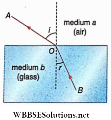
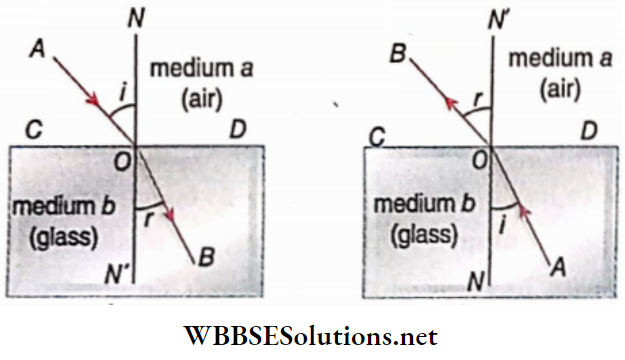
When a ray of light travelling in one medium enters another medium obliquely, the ray changes its direction at the interface. This phenomenon is known as the refraction of light. CD be the plane of separation of the media—air and glass

It is called a refracting surface. The ray AO incident obliquely at 0, changes direction after refraction and goes along the line OB. NON’ is drawn perpendicular to the surface of separation. The perpendicular to CD, NON’ is called normal. AO is the incident ray and OB is the refracted ray. The angle between the incident ray and the normal to the surface of separation at the point of incidence is called the angle of incidence

The angle between the refracted ray and the normal to the surface of separation is called the angle of refraction (r).

Class 12 Physics Unit 6 Optics Chapter 2 Refraction Of Light Deviation Of Ray

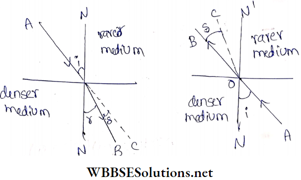
Refraction from rarer to denser medium:

If the ray travels from an optically rarer medium to a denser medium, say from air to glass, the refracted ray bends towards the normal. Here i>r.

Refraction from denser to the rarer medium:

If the ray travels from denser to rarer medium, say from glass to air, the refracted ray bends away from the normal Here r>i.

Read and Learn More Class 12 Physics Notes

Refraction Of Light Laws Of Refraction

Refraction of light is governed by the following two laws, called
laws of refraction.

  1. The incident ray, the refracted ray and the normal at the point of incidence lie on the same plane.
  2. The ratio of the sine of the angle of Incidence to the sine of the angle of refraction is constant.
  3. This constant depends on the nature of the two concerned media and the colour of the ray used.

This second law of refraction is known as Snell’s law, named after Willebrord Snellius (1580-1626)

Refractive Index

If i is the die angle of incidence and r is the angle of refraction, then according to the second law,

⇒ \(\frac{\sin i}{\sin r}=\mu\) (pronounced as ‘mu’) = constant.

This constant is called the refractive index of the second medium concerning the first medium.

The value of the refractive index depends on:

  1. Nature of the two concerned media and
  2. Colour of the Incident light.

Whatever may be the value of the angle of incidence, the value of the refractive index will remain constant if the colour of the incident light (i.e., frequency) and the two media remain unchanged

Μ has no uni

Normal Incidence:

If a ray of light is incident perpendicularly on a refracting surface, then / = 0. According to Snell’s law

π sinr = sin 0 = 0 or, r = 0

So, the ray suffers no deviation

Relative refractive index:

When light passes from medium a into another medium b, the ratio of the sine of the angle of incidence to the sine of the angle of refraction is called the refractive index of medium b concerning medium a. It is denoted by and i.e.,

aμb=  \(\frac{\sin i}{\sin r}\)

[i = angle of incidence, r = angle of refraction]

This refractive index is called the relative refractive index. According to the principle of reversibility of light—a ray of light will follow the same path if its direction of travel is reversed.

Following this principle, we can say that the ray BO in medium b when incidents at an angle r on the interface of the second medium a, refracts at an angle i along the path OA. Comparing this figure with it is the opposite phenomenon.

Class 12 Physics Unit 6 Optics Chapter 2 Refraction Of Light Relative Refraction Index

Thus, \(b^{\mu_a}=\frac{\sin r}{\sin i}\)

Here bμa is the refractive index of medium a concerning medium b.

So, \(a_a \mu_b \times{ }_b \mu_a=\frac{\sin i}{\sin r} \times \frac{\sin r}{\sin i}\)

= 1

Or, aμb = \(\frac{1}{b^\mu}\)

For example, if the refractive index of water concerning air is \(\frac{4}{3}\), then the refractive index of air concerning water is\(\frac{3}{4}\)

Absolute refractive index:

When light is refracted from a vacuum to another medium, the ratio of, the sine of the angle of incidence to the sine of the angle of refraction is called the absolute refractive index of the medium

If the angle of incidence is i and the angle of refraction is r, then the absolute refractive index of the medium,

⇒ \(\mu=\frac{\sin i}{\sin r}\)

Therefore, the relative refractive index of a medium concerning a vacuum is the absolute refractive index of that medium. The refractive index of a vacuum is 1.

In general, the refractive index of a medium relative to an air medium is considered as the refractive index of that medium. But it is not absolute, 1 refractive index of the medium

It is an experimental fact that the difference in the values of the refractive index of a medium concerning air and its absolute refractive index is very small. For example, at STP, the absolute refractive index of air is 1.0002918. So the refractive index of any medium concerning air may be considered as its absolute refractive index

For example, the refractive index of glass is 1.5 which means that the refractive index of glass concerning air is 1.5. At STP, the absolute refractive index of air is 1.0002918 and the refractive index of glass concerning air is 1.5. Thus, the absolute refractive index of glass = \(\frac{1.5}{1.0002918}\) = 49956 ≈1.5 The Absolute refractive index of a medium is denoted by μ. If there is more than one medium μ1, μ2, μ3 then is used.

WBCHSE Class 12 Physics Notes For Refraction Of Lights

Optical Density of a Medium

If the absolute refractive index (μ1) of any medium is greater than that of another medium (μ2), then the first medium is called optically denser and the second medium is called optically rarer. So, μ12 if then medium 1 is optically denser concerning medium 2 i.e., medium 2, is optically rarer concerning medium 1.

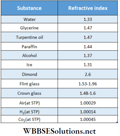
The optical density of a medium has no relation with its physical density or specific gravity. For example, the specific gravity of turpentine oil is 0.87 and that of water is 1. But the refractive index of turpentine oil is 1.47 and that of water is 1.33.

The refractive index of a medium depends on the colour of the incident light. It is greater for blue or violet than for red. The refracted ray in the case of violet light bends more than in the case of red light. The refractive index for yellow light is midway between these two.

So unless otherwise stated, the refractive index of a medium refers to yellow light.

Refractive indices of a few substances:

Class 12 Physics Unit 6 Optics Chapter 2 Refraction Of Light Refractive Indices Of A New Substances

Refractive Index and Related Terms

Relation between the velocity of light and refractive index:

According to the wave theory of light, the velocity of light is different in different media. If pt is the absolute refractive index of a medium, then

μ = \(\frac{\text { velocity of light in vacuum }(c)}{\text { velocity of light in that medium }(v)}\)

∴ Speed of light in free space = ft x speed of light in that medium

For any medium μ > 1, so speed of light in a vacuum is greater than that in any medium. Thus, the speed of light is maximum in a vacuum.

Accordingly, if and is the refractive index of the medium b concerning medium a, then

⇒ \(a^{\mu_b}=\frac{\text { velocity of light in medium } a}{\text { velocity of light in medium } b}\)

= \(\frac{v_a}{v_b}\)

Medium b is denser than medium a then aμb > 1 and in this case va>vb.

The velocity of light in a denser medium is less than the velocity of light in a rarer medium. The velocity of light in a medium decreases with the increase of its refractive index.

Thus if the velocity of light in medium b is lesser, i.e., medium b is optically denser, and aμb > 1 i.e., sin i>sinr or i< r. Thus, the angle of refraction is less than the angle of incidence, so the refracted ray bends towards the normal.

From the above discussion, it is clear that refraction variation in the speed of light in different media

Relation between relative refractive index and absolute refractive index:

If μ a and μb are absolute refractive indices of media a and b respectively

⇒ \(\mu_a=\frac{c}{v_a} \text { and } \mu_b=\frac{c}{v_b}\)

So relative refractive index of medium b concerning medium a,

⇒ \({ }_a=\frac{v_a}{v_b}=\frac{\frac{c}{v_b}}{\frac{c}{v_a}}=\frac{\mu_b}{\mu_a}\)

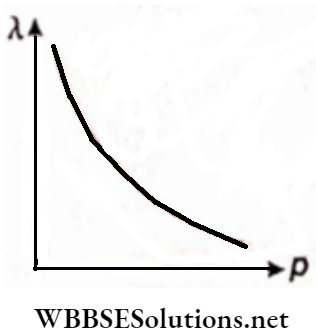
Relation of the wavelength of light with refractive index:

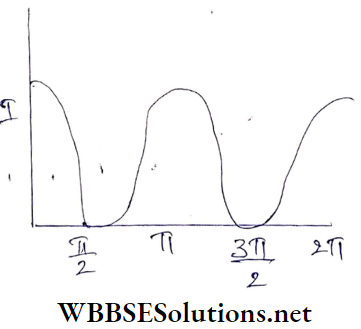
The relative refractive index between two media depends on the wavelength of light. Cauchy’s equation for the dependence of refractive index on the wavelength of light is

⇒ \(\mu=A+\frac{B}{\lambda^2}\)

Class 12 Physics Unit 6 Optics Chapter 2 Refraction Of Light Relation Of Wavelength Of Light

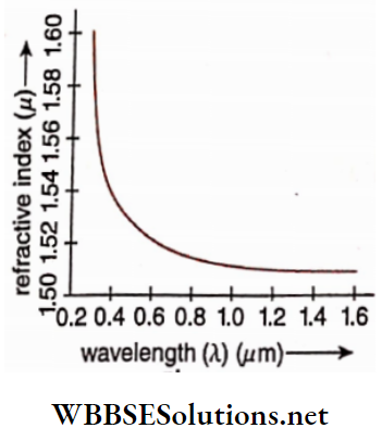
Here A and B are two constants; their values are different in different media. The refractive index of a medium decreases if the wavelength of light increases. The graph shows the variation of n with μ  with λ of BK7 glass.

In a medium apart from free space different coloured light travels at different speeds. In a particular medium red travels the fastest and violet travels the slowest. Thus refractive index of any medium for the red colour is the lowest and that for the violet colour is the highest. This is the reason why white light is dispersed

Relation of temperature with refractive index:

Generally, the refractive index of a medium decreases if the temperature of the medium increases. For a solid medium this change is small, for a liquid it is moderate and for a gas it is remarkable

It is to be remembered that, velocity, intensity and wave¬ length of light change due to refraction but its frequency and phase remain unchanged

Generalised Form of Snell’s Law

Let AB be the surface of the separation of two media 1 and 2. Medium 2 is denser and medium 1 is rarer. PO is the incident ray at the point O on the surface of separation and OQ is A the refracted ray at the point O . Let angle of incidence = i1 angle of refraction = i2

By Snells law \(\frac{\sin l_1}{\sin i_2}\)

We known \({ }_1 \mu_2=\frac{\mu_2}{\mu_1}\)

∴ \(\begin{equation}\frac{\sin i_1}{\sin i_2}=\frac{\mu_2}{\mu_1} \quad \text { or, } \mu_1 \sin i_1=\mu_2 \sin i_2\end{equation}\) …………………………. (1)

So for n number of media, it can be written as

\(\mu_1 \sin i_1=\mu_2 \sin i_2=\cdots=\mu_n \sin i_n\) …………………. (2)

This equation is known as the generalised form ofSnell’s law

Refraction Of Light Laws Of Refraction Numerical Examples

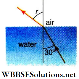
Example 1. A ray of light is incident from water on the surface of separation of air and water at an angle of 30°. Calculate the angle of refraction in air mu \(\frac{4}{3}\)
Solution:

Let the angle of refraction of the ray of light in the air be r

Since the ray of light is refracted from water to air,

⇒ \(w^\mu{ }_a=\frac{\sin i}{\sin r}\)

Or, \(\frac{1}{a^{\mu_w}}=\frac{\sin 30^{\circ}}{\sin r}\)

Or, \(\frac{1}{\frac{4}{3}}=\frac{1}{2 \sin r}\)

Or, \(2 \sin r=\frac{4}{3}\)

Or, \(\sin r=\frac{2}{3}\)

= 0.666

= sin 41.8°

or = r= 41.8°

Class 12 Physics Unit 6 Optics Chapter 2 Refraction Of Light Refraction In Air

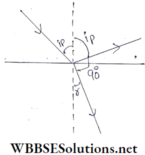
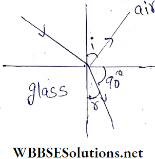
Example 2. A ray of light is incident on a block of glass in such a way that the angle between the refracted ray and the refracted ray is 90°. Determine the relation between the angle of incidence refractive index of
Solution:

Here angle of incidence = i

The angle of reflection = i, angle of refraction = r

The angle between the reflected ray and the refracted ray = 90°

According to the

i+90°+r= 180°

Or, r = 90°-i

The refractive index of glass,

μ = \(\mu=\frac{\sin i}{\sin r}=\frac{\sin i}{\sin \left(90^{\circ}-i\right)}\)

= \(\frac{\sin i}{\cos i}\)

= tan i

Class 12 Physics Unit 6 Optics Chapter 2 Refraction Of Light Reflected Ray

Example 3.  The refractive index of glass is 1.5 and the refractive index of water is 1.33. If the velocity of light in glass is 2 × 10⁸ m s1 what is the velocity of light In water?
Solution:

μg = \(\frac{\text { velocity of light in vacuum }}{\text { velocity of light in glass }\left(v_g\right)}\)

Or, velocity light in a vacuum

Again, \(\mu_w=\frac{\text { velocity of light in vacuum }}{\text { velocity of light in water }\left(v_w\right)}\)

Or, Velocity of light in vacuum = μw. vw

μg vg= μw vw

Or, \(\frac{\mu_g v_g}{\mu_w}=\frac{1.5 \times 2 \times 10^8}{1.33}\)

= 2.26x × 108 m s1

Example 4. A monochromatic -ray of light-, is refracted from the vacuum. to a medium of refractive index pi. Determine the relation of the wavelengths of light in vacuum and in glass
Solution:

μ = \(\frac{c}{v}=\frac{n \lambda_0}{n \lambda}=\frac{\lambda_0}{\lambda}\)

So, λ0 = μ λ

[Here, c and v are the velocities of light in vacuum and the medium respectively; n = frequency of light, which remains unchanged on refraction λ0, λ = wavelengths in vacuum and in the medium respectively.]

Example 5. If a ray of light is incident on a plate inside the water at an angle of 45°, what is the angle of refraction inside the plate? Given that the absolute refractive Indices of the plate and water are 1.88 and 1.33 respectively.
Solution:

Let the angle of refraction inside,n-rriDT.tile plate be r

Here , \(w^{\mu_g}=\frac{\sin i{ }^0}{\sin r} \text { or, } \frac{\mu_g}{\mu_w}=\frac{\sin i}{\sin r}\)

Or, \(\frac{1.88}{1.33}=\frac{\sin 45^{\circ}}{\sin r}\)

Or, in r = \(\frac{1}{\sqrt{2}} \times \frac{1.33}{1.88}\) = 0.5

= \(\frac{1}{2}\)= sin 30°

r = 30°

Example 6. How much time will sunlight take to pass through the glass window of thickness 4 mm ? μ of glass =1.5.
Solution:

Velocity of sunlight in a vacuum or air,

C = 3×10⁻⁸m s-1

Thus velocity in a medium of refractive index μ

u = \(v\frac{c}{\mu}\)

So, to cross a thickness d, the time taken by light,

t = \(\frac{d}{v}=\frac{d \mu}{c}\)

= \(\frac{\left(4 \times 10^{-3}\right) \times 1.5}{3 \times 10^8}\)

[here d= 4 mm = 4 ×10m]

= 2 × 10-11 s

Example 7. Green light of wavelength 5460 A°Is incident on an airglass interface. If the refractive index of glass is 1.5 what will be the wavelength of light In glass?
Solution:

The wavelength of the light in air, A0 = 5460 A°

The refractive index of glass concerning air, μ = 1.5

If the wavelength of the light In glass is λ, then

= \(\frac{\lambda_0}{\lambda}\)

Or, λ = \(\frac{\lambda_0}{\mu}=\frac{5460}{1.5}\)

= 3640 A°

Refraction Of Light Deviation Of A Ray

During reflection or refraction, the change In the direction of the tight is called its deviation.

The angle between the refracted ray and the direction of the incident ray gives the measure of deviation.

Deviation of incident ray AO, which after refraction proceeds along OD instead of OC. So the deviation of ray, S = ∠BOC

Class 12 Physics Unit 6 Optics Chapter 2 Refraction Of Light Medium Glass And Medium Air

Now, δ = ∠BOC = ∠N’OC- ∠N’OB

= ∠AON- ∠N’OB = i-r

We know. If the angle of Incidence Increases, the angle of refraction also Increases

For normal Incidence, i = 0 thus r = 0 and so δ = 0 (minimum).

For  i = 90°, δ Is maximum

For refraction to a rarer medium from a denser medium, the angle of refraction is greater than the angle of incidence, l.e., r> i.

Now, δ = ∠BOC = ∠N’OB- ∠N’OC

=∠N’OB-  ∠AON =r – i

Optics

Refraction Of Light Image Due To Refraction

Suppose, a beam of rays from a point object after refraction reaches our eyes in another medium. Now if dierefracted rays are produced backwards they are nice at a point It seems that the refracted rays are diverging from die second point. The second point Is the image of the lift’s first point. The image of any point object is formed in the same way. Thus a complete image of the object is formed.

If the object Is situated In a denser medium and Is viewed from a rarer medium, It appears (closer to the surface of separation. For example, If we look at a fish inside water in a pond it appeals nearer to the surface than the actual position.

If the object Is situated in a rarer medium and Is viewed from a denser medium, it appears to move away from the surface of separation, for example, our earth is surrounded by a thick atmospheric layer composed of different gases. Starlight comes to our eyes through this atmosphere. Hence we are the observers on Earth in a denser medium whereas the stars are in a vacuum i.e., in the rarer medium. So, the animal position of a star Is far behind its normal viewing position.

Object In denser medium end eyes In rarer medium:

Let the refractive indices of the two media a and b be μ1 and μ2, respectively and μ11, An object P situated in a is viewed from b. The surface of separation of a and b is a plane surface. A ray of light from P incident perpendicularly at A proceeds along AB without changing its direction. Another oblique ray PC incident at C is refracted along CD.

The refracted rays A B and CP when produced backwards meet at Q . So when the two refracted rays reach the rays of the observer. It will appear as if tyre two rays are coming from Q . So Q h the virtual Image of p.  In this case, the image rises towards the surface of the separation

Class 12 Physics Unit 6 Optics Chapter 2 Refraction Of Light Denswe Medium And Eye In Rarer

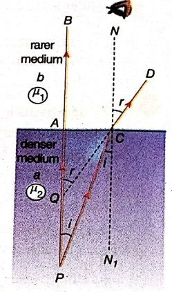
If the angle of incidence and the angle of refraction are l and r.

⇒ \(\frac{\mu_2}{\mu_1}=\frac{\sin r}{\sin i}=\frac{\tan r}{\tan i}=\frac{A C / A Q}{A C / A P}=\frac{A P}{A Q}\)

For near-normal viewing, points A and C are close enough. So sin0 *s tarif

Hence, \(\frac{\mu_2}{\mu_1}=\frac{\sin r}{\sin i}=\frac{\tan r}{\tan l}=\frac{A C / A Q}{A C / A P}=\frac{A P}{A Q}\)………………………….(1)

If the observer is In the air then μ1  = 1

Putting μ1 = 1 and μ2 =μ  (say) In equation (1) and writing AP = u, AQ =  v

We have \(\mu=\frac{A P}{A Q}=\frac{u}{v}\)

If d is die real deeds of the object then

μ = \(\frac{d}{\text { apparent depth of the object }}\)

Or, Apparent depth of the object = \(\frac{d}{\mu}\)

Hence apparent displacement

x = PQ = AP-AQ = d- \(\frac{d}{\mu}\)

= \(d\left(1-\frac{1}{\mu}\right)\)

Therefore, the apparent displacement of an object depends on the real depth (d) of the object and the refractive index (/z) of the denser medium.

The refractive index of water concerning air is|. If an object immersed in water is observed vertically from above the water, then its apparent displacement.

x = \(d\left(1-\frac{1}{4 / 3}\right)=\frac{d}{4}\)

General case:

The apparent depth of an object when viewed from the air through successive media of thicknesses d1 d2, d3 ‘ ……….. dn having refractive indices μ1,  μ2, μ3 ‘ ……….. μn  respectively is

= \(\frac{d_1}{\mu_1}+\frac{d_2}{\mu_2}+\frac{d_3}{\mu_3}+\cdots+\frac{d_n}{\mu_n}=\sum_{i=1}^n \frac{d_i}{\mu_i}\)

Its apparent displacement is

⇒ \(d_1\left(1-\frac{1}{\mu_1}\right)+d_2\left(1-\frac{1}{\mu_2}\right)+d_3\left(1-\frac{1}{\mu_3}\right)+\cdots+d_n\left(1-\frac{1}{\mu_n}\right)\)

= \(\sum_{i=1}^n d_i\left(1-\frac{1}{\mu_i}\right)\)

Object in rarer medium and eye in denser medium:

Let the refractive indices of the two media a and b be μ2 and μ2 respectively and μ2 > μ1 An object P is situated in the medium b and it is seen from the medium. The surface of separation of a and b is a plane surface.

A ray of light from P is incident perpendicularly at point A on the surface of separation and proceeds straight along AB through the medium a without changing its direction. Another oblique ray PC is incident at C and proceeds along CD after j refraction. The refracted rays AB and CD when produced backwards meet at Q. So when the two refracted rays reach the observer, they will.

Class 12 Physics Unit 6 Optics Chapter 2 Refraction Of Light Rarer Medium And Eye

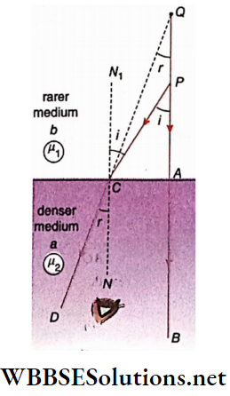
Appears to him that the two rays are coming from Q. So Q is the virtual image of P. In this case, the image appears to move farther away from the surface of separation.

If the angle of incidence and the angle of refraction of the incident ray at C are i and r respectively, then according to Snell’s law

μ1 sin i= μ2sin r

∴ \(\frac{\mu_2}{\mu_1}=\frac{\sin i}{\sin r}=\frac{\sin \angle P C N_1}{\sin \angle N C D}\)

Since the two lines PAB and NjCiV are parallel

∠PCN1 = ∠APC and ∠NCD = ∠AQC

⇒ \(\frac{\mu_2}{\mu_1}=\frac{\sin \angle A P C}{\sin \angle A Q C}=\frac{\frac{A C}{C P}}{\frac{A C}{C Q}}=\frac{C Q}{C P}\)

If the points A and C are very close to each other i.e., if the ray PC is not so oblique, then CP ≈ AP and CQ ≈ AQ

∴ \(\frac{\mu_2}{\mu_1}=\frac{A Q}{A P}\)…………. (3)

If the rarer medium in which the object is situated is air then = 1.

Putting μ1 = 1 and μ2= p (say) in equation (3) we get

⇒ \(\mu=\frac{A Q}{A P}\)

The refractive index of the denser medium concerning air apparent height of the object from

= \(\frac{\text { the surface of separation }}{\text { real height of the object from the surface of separation }}\)

If the real height of the object, AP = μd, then

= \(\mu\frac{\text { apparent height of the object }(A Q)}{d}\)

Or, AQ = μd ………………… (4)

So the apparent displacement of the object

=PQ = AQ – AP – μd-d = (μ-1) d

General case:

The apparent height of an object in the air when viewed from a medium of refractive index pn through successive media of thicknesses d1 d2, d3 ‘ ……….. dn having refractive indices, μ1,  μ2, μ3 ‘ ……….. μn   respectively is

⇒ \(\mu_1 d_1+\mu_2 d_2+\cdots+\mu_n d_n=\sum_{i=1}^n \mu_i d_i\)

Its apparent displacement is

⇒ \(\left(\mu_1-1\right) d_1+\left(\mu_2-1\right) d_2+\cdots+\left(\mu_n-1\right) d_n\)

= \(\sum_{i=1}^n\left(\mu_i-1\right) d_i\)

Let an object in a medium of refractive index fly be viewed from a medium of refractive index  Then we have,

= \(\frac{\text { Apparent depth of the object }}{\text { real depth of the object }}=\frac{\mu_2}{\mu_1}\)

=  \({ }^1 \mu_2\)

If the object is situated in a comparatively denser medium, then μ12.

In that case, apparent depth < real depth. If the object is situated in a comparatively rarer medium then μ12 In that case, apparent depth > real depth

Image Formed by Oblique Incident Rays

In the last section, we talked of almost normal viewing. For more B oblique incidence, the apparent displacement is higher

Class 12 Physics Unit 6 Optics Chapter 2 Refraction Of Light Oblique Incident Rays

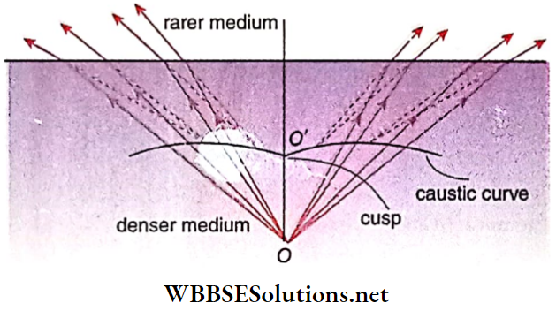
A point object O in an optically denser medium (say, water) is viewed from a rarer medium (say, air), at different angles. For different positions of the observer, the locus of the different positions of the image is a curved line. This curved line is called a caustic curve. The curve has two parts. These two parts meet at a point O’, known as the cusp. The image of an object at O when viewed vertically downward, is formed, at O’.  shows how the images A’, B’, C’, etc. of different points A, B, C, etc. on the base of a vessel or tank containing water will appear to an observer located at a given position. It is evident

Class 12 Physics Unit 6 Optics Chapter 2 Refraction Of Light Cusp Of Vertically Downward

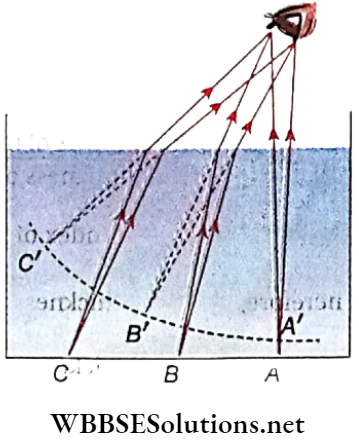
The image for normal incidence is at the lowest position. The other images go on rising as the oblique rays from the base produce the images. The image of the base of the vessel will be a curved surface indicated by A’B’C’. With the increase of the distance of the base of the vessel from the eye, the curved surface appears, to rise higher. So if an observer stands in a shallow pond having equal depth everywhere, it appears to him that the pond near his feet is the deepest

Image of an Object under a Parallel Slab

ABCD is a parallel glass slab. Its thickness is d and its refractive index μ,  P is a point object placed in air under the surface AB of the slab. A ray of light PX normally incident on AB goes undeviated along XY. Another ray PQ incident obliquely is refracted along QR. After that, the ray is further refracted along RS. Since the two faces AB and DC of the glass slab are parallel, the rays

PQ and RS will be parallel. So an observer from above the slab will see the image of P at P’. PP’ is the apparent displacement of the point object towards the observer. The normal NQN1 at Q intersects P’R at M. The quadrilateral PP’MQ is a parallelogram

PP’ = QM

The Apparent Displacement of the point object

∴ \(d\left(1-\frac{1}{\mu}\right)\)

PQ and RS will be parallel. So an observer from above the slab will see the image of P at P’. PP’ is the apparent displacement of the point object towards the observer.

The normal NQN1 at Q intersects P’R at M. The quadrilateral PP’MQ is a parallelogram.

∴ PP’ = QM

∴ The apparent displacement of the point object

= PP’ = QM

= d(1- \(\frac{1}{\mu}\))

So the apparent displacement of an object does not depend on the position of the object under the lower face of the glass slab. It only depends on the thickness of the slab (d) and the refrac¬ index of its material (μ).

 Optics

Refraction Of Light Some Examples Of Refraction

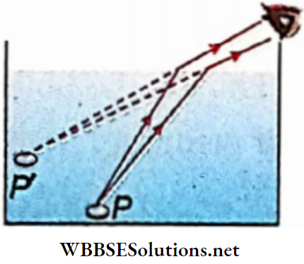
A coin immersed in water:

A coin is placed at the bottom of a pot such that the coin is just not visible. If eyes are set at the same position and the pot is now filled with water, the coin becomes visible. Because the rays from P are refracted from denser to rarer medium and are bent away from the normal, they reach our eyes. As a result, the refracted rays appear to diverge from P’, i.e., the virtual image of the coin is formed at P’, situated above the coin.

Class 12 Physics Unit 6 Optics Chapter 2 Refraction Of Light A Coin Immersed In Water

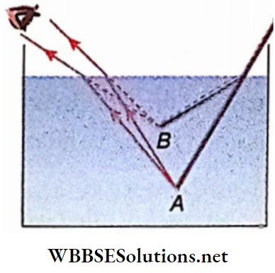
A rod partly immersed in water:

Let a straight rod be partly immersed in water. When the rod is held obliquely in water, the portion of the rod in water will appear to be bent upward [Fig. 2.20]. The reason is the same as above. The light rays coming from the portion immersed in water are refracted from denser to rarer medium and hence bent away from the normal. So point A of the rod appears to be raised at B. This happens for every point of the immersed portion of the rod

Class 12 Physics Unit 6 Optics Chapter 2 Refraction Of Light A Rod Partly Immersed In Water

Object and medium having approximately equal refractive index:

An object becomes invisible when it is sur¬ rounded by a medium having a nearly equal refractive index. Since the refractive indices of both of them are almost the same, negligible refraction does occur from their surface of separation, and for refraction lending of light is negligible. i.e., it travels undefeated. As a result, the surface of separation is not visible. ff99Wt9rf . The refractive indices of glycerine and glass are almost equal. So when a glass rod is immersed in glycerine thiqÿrod is not visible

Multiple images in a thick glass mirror:

If an object is placed in front of a thick mirror with silvered glass at the mirror at the back if a surface object is viewed from a slanting direction, a series of images are formed.

When ray PA is incident on the front face at point A, a very small portion of the light is reflected along AK producing a faint image at P1. The remaining larger portion of the light is refracted into the mirror along AB and is reflected along BC from the silvered surface. A large portion of this reflected ray within the glass comes out along CL producing the second image P2 which is the brightest of all the images.

The remaining part of the ray CD is reflected from surface Y to the silvered surface where it is again reflected. The process continues and gradually fainter images are formed. The different images lie on the line drawn perpendicular to the surface X from the object P.

Class 12 Physics Unit 6 Optics Chapter 2 Refraction Of Light Multiple Iamges In A Thick Glass Mirror

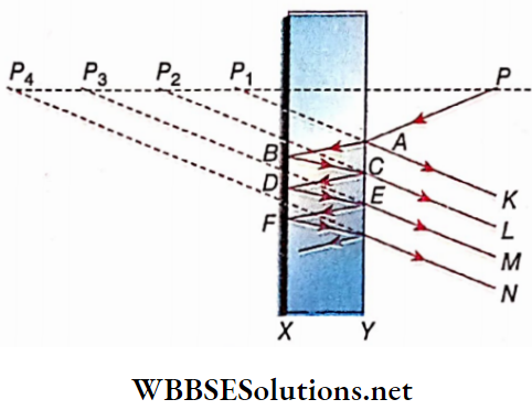
The ray BC, which is the first reflected ray from the silvered surface, is the brightest and it travels along CL. Consequently, image P2 is the brightest. Hence the brightest second image is considered to be the image of the object. The more oblique the incident rays are, the more the amount of reflection from the front surface of the mirror and the brightness of the image P1 will increase accordingly

Apparent thickness of thick glass mirror:

In the case of a water-filled bowl, the depth of the bowl appears to be less. Similarly, a thick glass mirror seems to be less thick than it is.

We have, \( \frac{\text { real thickness of mirror }}{\text { apparent thickness of mirror }}\)

= Refractive index of glass = \(\frac{3}{2}\)

Therefore, the apparent thickness of a mirror

= \(\frac{2}{3 }\) × Real thickness of the mirror

Optics

Refraction Of Light Some Examples Of Refraction Numerical Examples

Example 1. There is a mark at the bottom of the beaker. A liquid with a refractive index of 1.4 is poured into it. If the depth then determines how much the (liquid is 3.5 cm mark appears to rise when it is viewed from above.
Solution:

If the object is in a denser medium and the observer is in a rarer medium, the refractive index of the denser medium relative to the rarer medium

= \(\frac{\text { real depth of the object }}{\text { apparent depth of the object }}\)

Or, 1.4 = \(\frac{3.5}{\text { apparent depth of the object }}\)

Or, apparent depth of the object = \(\frac{3.5}{1.4}\)

= 2.5 cm

Apparent upward displacement of the mark

= 3.5 – 2.5 = 1cm

Example 2.  There is a black spot at the bottom of a rectangular glass slab of thickness d and refractive index μ. When the spot is viewed perpendicularly from above, the spot appears to be shifted through a distance \(\frac{(\mu-1) d}{\mu}\) towards the observer. Prove it.
Solution:

The real depth of the black spot from the upper surface of

Let the apparent depth of the black spot from the upper surface of the glass slab be d2

Refractive index of glass \(\mu=\frac{d}{d_1}\)

Or, \(d_1=\frac{d}{\mu}\)

∴ The apparent displacement of the black spot towards the observed

= \(d-d_1=d-\frac{d}{u}\)

= \(d\left(1-\frac{1}{\mu}\right)=d\left(\frac{\mu-1}{\mu}\right)\)

Example 3.  In a beaker partly filled with water, the depth of water seems to be 9 cm. On pouring more water into it, the real depth of water is increased by 4cm. Now the apparent depth of water seems to be 12cm. Determine the refractive index of water and the initial depth of water in the beaker.
Solution:

Let the refractive index of water be ft and the initial| depth of water in the beaker be x.

μ = \(\frac{x}{9}\)

or, x = 9μ

When more water is poured into the beaker, the real depth of water becomes (x + 4) cm.

In the second case, μ = \(\frac{x+4}{12}\)

Or, 12 μ = x + 4 or; 12 μ = 9 μ + 4 Or, 3 μ= 4

∴ μ = \(\frac{4}{3}\)

μ = 1.33

Initial depth of water in the beaker.

x = 9 μ = 9 ×  \(\frac{4}{3}\)

= 12cm

Example 4. A small air—bubble exists inside a transparent cube of side 15 cm each. The apparent distance of the bubble observed from one face is 6 cm and from the opposite face its apparent distance becomes 4 cm. Determine the real distance of the bubble from the first face and the refractive index of the material of the cube
Solution:

Let the real distance of the bubble from the first face be x cm.

The real distance of the bubble from the opposite face = (15-x) cm

Let the refractive index of the material of the cube be ft.

We know if the object lies in a denser medium and eye in the rarer medium,

μ = \(\frac{\text { real distance }}{\text { apparent distance }}\)

In the first case , μ=  \(\frac{x}{6}\)

In the second case,  μ  = \(\frac{15-x}{4}\)

⇒ \(\frac{x}{6}=\frac{15-x}{4}\)

Or, 4x = 90- 6x

Or, 10x = 90

Or, x = 9cm and

mu = \(\frac{9}{6}\) = 1.5

Therefore, the real distance of the bubble from the first face is 9 cm and the refractive index of the material of the cube is 1.5

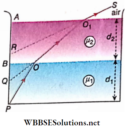
Example 5. A vessel is filled with two mutually immiscible liquids with refractive indices μ1  and μ2. The depths of the two liquids are d1 and d2 respectively. There is a mark at the bottom of the vessel. Show that the apparent depth of the mark when viewed normally is given by \(\left(\frac{d_1}{\mu_1}+\frac{d_2}{\mu_2}\right)\)
Solution:

The image of P is formed at Q due to refraction at the surface of separation B of the 1st and 2nd liquid. Another final image due to refraction in air from the second liquid is formed at R

For the first refraction:

⇒ \(\frac{\mu_1}{\mu_2}=\frac{B P}{B Q}\)

Or, \(B Q=\frac{\mu_2}{\mu_1} \cdot B P\)

⇒ \(\frac{\mu_2}{\mu_1} d_1\)

For the second refraction:

⇒ \(\frac{\mu_2}{1}=\frac{A Q}{A R}\)

Or, \(A R=\frac{A Q}{\mu_2}\)

= \(\frac{1}{\mu_2}(A B+B Q)\)

Or, \(A R=\frac{1}{\mu_2}\left(d_2+\frac{\mu_2}{\mu_1} d_1\right)\)

= \(\frac{d_2}{\mu_2}+\frac{d_1}{\mu_1}\)

The apparent depth of the mark P when viewed normally

= AR = \(\frac{d_1}{\mu_1}+\frac{d_2}{\mu_2}\)

Class 12 Physics Unit 6 Optics Chapter 2 Refraction Of Light Mutually Immiscible Liquids

Example 6. A rectangular slab of refractive index [i is placed on another slab of refractive index 3. Both the slabs are of ror. the displacement of the image? the same dimensions. There is a coin at the bottom of the lower slab. What should be the value of n such that when viewed normally from above, the coin appears to be at the surface of separation of the two slabs?
Solution:

Let the thickness of each slab be d. According to the question the apparent depth of the coin =d

d = \(\frac{d}{\mu}+\frac{d}{3}\)

Or, 1= \(\frac{1}{\mu}+\frac{1}{3}\)

Or, \(\frac{1}{\mu}=\frac{2}{3}\)

Or, \(\frac{3}{2}\)

= 1.5

Example 7. A tank contains ethyl alcohol of a refractive index of 1.35 The depth of alcohol is 308 cm. A plane mirror is placed horizontally at a depth of 154 cm in it. An; object is placed 254 mm above the mirror. Calculate the apparent depth of the image formed by the mirror
Solution:

Depth of the mirror =1.54 m; object distance from the mirror = 0.254 m

The image of the object is formed at a distance of 0.254 m behind the mirror

= \(\frac{\text { real depth }}{\mu}\)

=\(\frac{1.794}{1.35}\)

= 1.33m

Example 8. A 20mm thick layer of water \(\left(\mu=\frac{4}{3}\right)\) 35mm thick layer of another liquid \(\left(\mu=\frac{7}{5}\right)\) = ‘ in a tank. A small coin lies at the bottom of the tank. Determine the apparent depth of the coin when viewed normally from above the water
Solution:

Real depth of the coin d+d = 20+ 35 = 55m m

∴ A parent depth of the coin

= \(\frac{d_1}{\mu_1}+\frac{d_2}{\mu_2}=\frac{20}{\frac{4}{3}}+\frac{35}{\frac{7}{5}}\)

= 15+ 25

= 40 mm

Example 9. If a point source is placed at a distance of 18 cm from the pole of a concave mirror, its image is formed at a distance of 9 cm from the mirror. A glass slab of thickness 6 cm is placed between the point source and the mirror such that the parallel faces of the glass slab remain perpendicular to the principal axis of the mirror the refractive index of glass is 1.5 what will be the displacement of the image?
Solution:

Let P be the position of the object and in the absence of the glass slab, Q be the position of the image formed by the concave mirror

u = 18 cm,

OQ = v= 9 cm

According to \(\frac{1}{v}+\frac{1}{u}=\frac{1}{f}\) we get,

= \(\frac{1}{-9}+\frac{1}{-18}=\frac{1}{f}\)

Or, f= -6 cm

If the glass slab of thickness 6 cm is placed between the point I source and the concave mirror, apparent displacement of the I Point source will take place towards the mirror. The rays coming from P appear to come from P’ after refraction.

The apparent displacement of P

PP’ = \(d\left(1-\frac{1}{\mu}\right)\)

= 6\(\left(1-\frac{1}{1.5}\right)\)

= 2cm

So in the second case, object distance u = -(18- 2) = -16 cm ; f = -6 cm; v = ?

We know, \(\frac{1}{v}+\frac{1}{u}=\frac{1}{f}\) Or, \(\frac{1}{v}+\frac{1}{-16}=\frac{1}{-6}\)

Or, \(\frac{1}{v}=\frac{1}{-6}+\frac{1}{16}=\frac{-10}{96}\)

Or, v = \(-\frac{96}{10}\)

= – 9.6 cm

Displacement of the image

QQ’ = OQ’ OQ – OQ = 9.6- 9 = 0.6 cm

Example 10. A plane is made of glass having a thickness of 1.5 cm. Its back surface is coated with memory. A man is standing at a distance of 50 cm from the front face of the mirror. If he looks at the mirror normally, where can he find his image behind the front face of the mirror? The refractive index of glass  = 1.5 
Solution:

The real depth of the mercury-coated surface from the upper surface of the mirror = 1.5 cm

If the apparent depth of the mercury coated mercury  cm, then \(\frac{1.5}{x}\) = 1.5 or, x= 1 cm

So the mercury-coated surface appears to be at n distance of 1 cm from the front face of the mirror.

‘Therefore, the distance of the man from the appetent position of the mercury-coated surface a = 50 +1  cm

So the distance of the Image from the apparent position of the mercury-coated surface =  51 cm

The distance of the Image of the man from the front tuifnee of the mirror =51 + 1 = 52 an

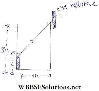
Example 11.  An observer can see the topmost point of a narrow rod of height through a small hole  The rod Is placed Inside a beaker. The beaker’s height is 3h and its radius Is h. When the beaker Is filled up to 2 h of its height with a liquid the observer can see the entire rod. What Is the value of the refractive Index of the liquid?

Class 12 Physics Unit 6 Optics Chapter 2 Refraction Of Light A Ray Light The Beaker Height And Radius

Solution:

Let us assume that  PQ is a thin straight rod kept in a beaker. B Is a small hole in the wall of the beaker. When the beaker is filled with a liquid up to a height of 2h, then Q can be seen through hole B.

Here, QD ray propagates through the liquid and gets refracted along DB in the air

According to ABRP is a square midpoint of the diagonal PB.
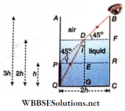
Class 12 Physics Unit 6 Optics Chapter 2 Refraction Of Light A Ray Light MidPoint Of The Diagnoal

Here DE= PE = h

Again, ∠BDP = 45°  [∴ ∠DPE ]

Since the object was placed in the denser medium, according to Snell’s law

⇒ \(\frac{1}{\mu}=\frac{\sin i}{\sin r}=\frac{\frac{Q G}{Q D}}{\sin 45}\)

Or, \(\frac{1}{\mu}=\frac{\frac{h}{\sqrt{5 h}}}{\frac{1}{\sqrt{2}}}\)

Since,  QD2=QG2+GD2=h2+(2 h)2= 5 h2

Or, \(\frac{1}{\mu}=\sqrt{\frac{2}{5}} \quad \text { of, } \mu=\sqrt{\frac{5}{2}}\)

Therefore, the required refractive Index of the liquid is \(\sqrt{\frac{5}{2}}\)

Example 12. A ray of light Incident at the Interface of glass and water at an angle of Incidence i. If the ray finally emerges parallel to the surface of water Then what will be the value of μg?
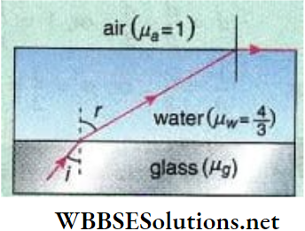
Class 12 Physics Unit 6 Optics Chapter 2 Refraction Of Light Interface Of Glass

Solution:

When refraction occurs due to the propagation of light rays from glim to water, we may write from Snell’s law,

⇒ \(\mu_g \sin i=\mu_w \sin r\) …………..(1)

Again, when refraction occurs due to the propagation of light rays from water to air, we may write from Snail * law

⇒ \(\mu_g \sin i=\mu_w \sin r\) …………..(2)

Therefore, the required refractive Index of glass is \(\frac{1}{\sin i}\)

Optics

Refraction Of Light Critical Angle’s Total Internal Reflection

We know, in refraction from denser to a rarer medium light | bents away from the normal. As a result angle of refraction ’ becomes larger than the angle of incidence.

L line AB represents the surface of the separation of water and air.

Ray P1 O travelling through water is incident at O on the surface- of separation. A part of the ray is reflected into the water along OR1 and another part is refracted into the air along OQ1:  The angle of refraction ∠Q1ON is greater than the angle of incidence ∠P1 ON1. The greater the angle of incidence, the greater the angle of refraction and in each case, both reflection and refraction will take place.

For a particular value of the angle of incidence, the angle of refraction becomes 90°, so that the refracted ray grazes the surface of separation. This limiting angle of incidence in the denser medium is called the critical angle for the two given media. Thus, ∠P2ON1 = critical angle (θc). In this case, the angle of refraction ∠NOQ2 = 90°. Here also a part of the incident ray is reflected to water along OR2.

Class 12 Physics Unit 6 Optics Chapter 2 Refraction Of Light Critical Angle Of Total Internal Reflection

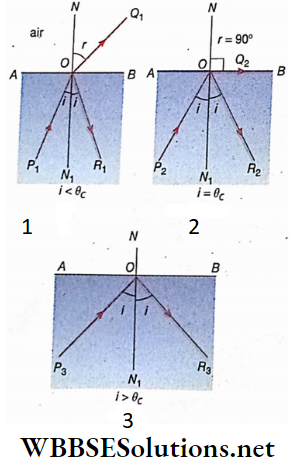
If the angle of incidence exceeds the critical angle i.e., if i  > θc [as in the case of the incident rayP3O ] no part of the incident ray is refracted in the second medium. The ray is completely reflected along OR3 into the first medium. This phenomenon is called total internal reflection. In this case, the surface of the separation of the two media behaves as a mirror.

Critical angle:

It is that particular angle of incidence of a ray of light for a given pair of media, passing from denser one to rarer one, for which the corresponding angle of refraction is equal to 90 0 and the refracted ray grazes along the surface of the interface separating the two media. The critical angle of a pair of media depends on the colour of the incident light and the nature of the two media.

For example, in the case of two particular media, the critical angle for red light is greater than that for violet light. Again, the critical angle of water to air is 49°, while that of glass to air is 42°. The statement, ‘critical angle of glass to air is 42° ‘ means that a . ray of light from glass being incident on the surface of separation of glass and water at an angle of 42°, should go along the surface of separation after refraction i.e., the refracted angle will be 90°.

Total internal reflection:

When a ray of light travelling from a denser medium to a rarer medium is incident at the surface of separation of the two media at an angle greater than the critical angle for the media, there is no refraction; rather the whole of the incident ray is reflected. This phenomenon is known as total internal reflection.

Condition of total internal reflection:

The conditions to be satisfied for total internal reflection are as follows

  1. The light must travel from a denser to a rarer medium.
  2. The angle of incidence must be greater than the critical angle for the two media

Reason for using the term “total’:

In ordinary reflection, a part of the incident light is reflected from the surface of separation and the rest is refracted. But in the case of internal reflection, no part of the incident light is refracted, rather the entire portion of the incident light is reflected to the first medium from the surface of separation of the two media. So this reflection is called total reflection.

Relation between critical angle and refractive index of the denser medium:

Let ∠P2ON1 = θc = critical angle between the two media, water and air, which

Impliesair concerning the angle to water of refraction is aμw, which is then 90°. If the refractive index

aμw = \(\frac{\sin \theta_c}{\sin 90^{\circ}}\)

Or,  sin θc = \(\frac{1}{a^{\mu_w}}\)

So, the value of critical depends on the refractive index of one medium concerning another

If the medium is a and b the,

⇒ \(\sin \theta_c=\frac{1}{b^{\mu_a}}=\frac{1}{\begin{array}{r}
\text { refractive index of denser medium } \\
\text {concerning rarer medium }
\end{array}}\)

= \(\frac{\mu_b}{\mu_a}=\frac{\text { absolute refractive index of medium } b}{\text { absolute refractive index of medium } a}\)

Optics

Refraction Of Light Critical Angle’s Total Internal Reflection Numerical Examples

Example 1. If the absolute refractive index of a medium is \(\sqrt{2}\), calculate the critical angle of glass to the medium. Given
Solution:

If the refractive index of glass concerning air is aμg, then

aμg= \(\frac{1}{\sin \theta_c}=\frac{1}{\sin 30^{\circ}}\)

= 2

If the refractive index of glass concerning the medium is mμg, then

aμg= \(\frac{a^{\mu_g}}{{ }_a \mu_m}\)

= \(\frac{2}{\sqrt{2}}\)

= \(\sqrt{2}\)

If the critical angle of glass to the medium is #c, then

sin = \(\sin \theta_c=\frac{1}{m^\mu}\)

= \(\frac{1}{m^\mu}=\frac{1}{\sqrt{2}}\)

= sin 45

Or, θc = 45

Example 2.  The refractive index of carbon disulphide for red light is 1.634 and the difference in the values of the critical angle for red and blue light at the surface of separation of carbon disulphide and air is 0°56/. What is the value of the refractive index of carbon disulphide for blue light
Solution:

Let the refractive index of carbon disulphide for red light = and circle angle =

Now, sin θr = \(\frac{1}{\mu_r}=\frac{1}{1.634}\)

= 0.6119 = sin 37.73

θr = 37.73

Let the critical angle for blue light be θb. The refractive index increases as the wavelength of light decreases. So the critical angle decreases.

∴ θbr

According to the Question,

θb = 37.73°-0°.56′

= 37.73°-0.93°

= 36.8°

So refractive index of carbon disulphide for blue light,

μb = \(\frac{1}{\sin \theta_b}=\frac{1}{\sin 36^{\circ} 48^{\prime}}\)

= \(\frac{1}{\sin 36.8^{\circ}}=\frac{1}{0.599}\)

= 1.669

Example 3. The refractive index of-diamond is 2.42,-which proves that all the beams of rays having an angle of incidence of more than 25° will be reflected, [sin 24.41° = 0.4132]
Solution:

If the critical angle is θc then

Sin θc = \(\frac{1}{\mu}=\frac{1}{2.42}\)

= 0.4312° = sin 24.41°

θc  = 24.41°

We know that if the angle of incidence of a ray of light is greater than the critical angle, the ray will be reflected. Here the critical angle is 24.41°. So rays of light having an angle of incidence greater than 25° will be reflected

Example 4. A ray of light will go from diamond to glass. What should be the minimum angle of incidence at the surface of separation of the two media, diamond and glass, so that the ray of light cannot be refracted in glass? μ of glass =1.51 and μ of diamond = 2.47; sin37.69° = 0.61134
Solution:

If the light ray is incident at the surface of separation of the two media diamond and glass at a critical angle, the ray is grazingly refracted in the glass. If the critical angle is QQ then

sin θc = \(\frac{1}{g^{\mu_d}}=\frac{1}{\frac{\mu_d}{\mu_g}}\)

= \(\frac{\mu_g}{\mu_d}=\frac{1.51}{2.47}\)

= 0.61134

= sin 37.69°

∴ θc  = 37.69°

So if the angle of incidence of a light ray is greater than 37.69° it | cannot be refracted in glass.

∴  Required minimum angle of incidence =37.69°

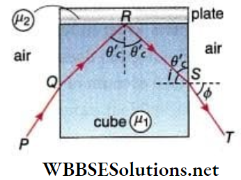
Example 5. cube has a refractive Index μ1. There is a plate of refractive Index μ221) A ray travelling through the air is incident on the side face of the cube. The refracted ray Is an Incident on the upper face of the cube at the minimum angle for total internal reflection to occur. Finally, the reflected ray emerges from the opposite face. Show that if the angle of emergence Is Φ then sin = \(\sqrt{\mu_1^2-\mu_2^2}\)
Solution:

PQ = incident ray on the side face of the cube, QR = refracted ray inside 0′ the cube, S = reflected ray from the upper face of the cube, ST = emergent ray from the opposite face.

Let the critical angle for total reflection be θc

According to the question θ’c ≈θc

⇒ \(\sin \theta_c^{\prime} \approx \sin \theta_c=\frac{1}{2^{\mu_1}}=\frac{1}{\frac{\mu_1}{\mu_2}}=\frac{\mu_2}{\mu_1}\)

Angle of incidence of the ray RS = l = 90° – θc and angle of refraction -tf>

⇒ \(\sin \theta_c^{\prime} \approx \sin \theta_c=\frac{1}{2^{\mu_1}}=\frac{1}{\frac{\mu_1}{\mu_2}}=\frac{\mu_2}{\mu_1}\)  = Refractive index of air with respect to the cube

= \(\frac{1}{\text { refractive index of the cube with respect to air }}\)

Or, \(\frac{\sin i}{\sin \phi}=\frac{1}{\mu_1}\)

Or, sin Φ = μ1 sin i

= \(\mu_1 \sin \left(90^{\circ}-\theta_c\right)=\mu_1 \cos \theta_c\)

= \(\mu_1, \sqrt{1-\sin ^2 \theta_c}\)

= \(\mu_1 \sqrt{1-\frac{\mu_2^2}{\mu_1^2}}=\sqrt{\mu_1^2-\mu_2^2}\)

Class 12 Physics Unit 6 Optics Chapter 2 Refraction Of Light A Cube Refractive Index

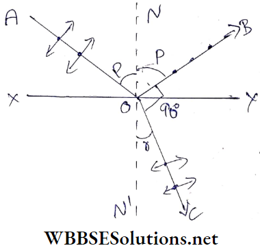
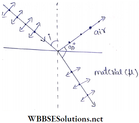
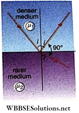
Example 6. A ray of light travelling through a denser medium is incident at an angle i in a rarer medium. If the angle between the reflected ray and the refracted ray is 90° show that the critical angle of the two media, \(\theta_c=\sin ^{-1}(\tan i)\) 
Solution:

Suppose the angle of refraction in the medium =r

From  we get

i+ 90° + r = 180°

Or, r = 90° – i

According to Snell’s law.

⇒\(\frac{\sin l}{\sin r}={ }_1 \mu_2=\frac{\mu_2}{\mu_1}\)

Or, \(\frac{\sin i}{\sin \left(90^{\circ}-i\right)}=\frac{\mu_2}{\mu_1}\)

Or, \(\frac{\sin i}{\cos i}=\frac{\mu_2}{\mu_1}\)

Or, \(\tan i=\frac{\mu_2}{\mu_1}\)

If the critical angle for the two media is θc, then

⇒ \(\sin \theta_c=\frac{1}{{ }_2 \mu_1}\)

= \(\frac{1}{\frac{\mu_1}{\mu_2}}=\frac{\mu_2}{\mu_1}\)

= tan i

Or, \(\theta_c=\sin ^{-1}(\tan i)\)

Class 12 Physics Unit 6 Optics Chapter 2 Refraction Of Light A Ray Light A Ray Of Light Travelling A Denser Medium

Example 7. A nail Is fixed up perpendicularly at the centre of a circular wooden plate. Keeping the nail at the bottom, the circular plate Is made to float In water. What should be the maximum ratio of the radius of the plate and the length of the nail so that the nail will be out of vision? Refractive index of water \(\frac{4}{3}\)
Solution:

AB Is the circular wooden plate and CD is the nail. Suppose, the radius of the plate =r and the length of the nail =h Since the nail Is not seen from the air, the angle of incidence of the ray DA will be greater than 0 and the ray will be reflected.

Class 12 Physics Unit 6 Optics Chapter 2 Refraction Of Light A Nail Is Fixed Perpendicularly At The Centre

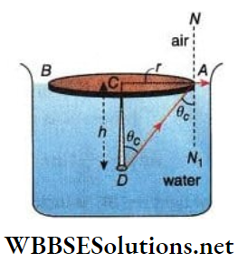
We know, \(\sin \theta_c=\frac{1}{a^\mu{ }_w}=\frac{3}{4}\)

⇒  \(\cos \theta_c=\sqrt{1-\frac{9}{16}}=\frac{\sqrt{7}}{4}\)

⇒ \(\tan \theta_c=\frac{\frac{3}{4}}{\frac{\sqrt{7}}{4}}=\frac{3}{\sqrt{7}}\)

Or, \(\frac{r}{h}=\frac{3}{\sqrt{7}}\)

This is the required ratio

Example 8.  The Critical angle of glass relative to a liquid is 57° 20′. Calculate the velocity of light in the liquid. Given,  μ of glass = 1.58, velocity of light in vacuum = 3×10⁸ m s-1 sin 57° 20′ = 0.8418
Solution:

Critical angle of glass relative to the liquid,

θc = 57°20′

If the refractive index of glass concerning the liquid is {fiR then.

sinθc =\(\frac{1}{\nu_g}=\frac{1}{\frac{\mu_g}{\mu_l}}=\frac{\mu_l}{\mu_g}\)

⇒ \(\frac{\mu_l}{\mu_g}=\sin 57^{\circ} 20^{\prime}\)

= 0.8418

Or, \(\mu_l=0.8418 \times \mu_g=0.8418 \times 1.58\)

Again , \(\mu_l=\frac{\text { velocity of light in vacuum }}{\text { velocity of light in the liquid }}\)

The velocity of the light in the liquid

= \(\frac{3 \times 10^8}{\mu_l}=\frac{3 \times 10^8}{0.8418 \times 1.58}\)

= \(2.255 \times 10^8 \mathrm{~m} \cdot \mathrm{s}^{-1}\)

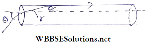
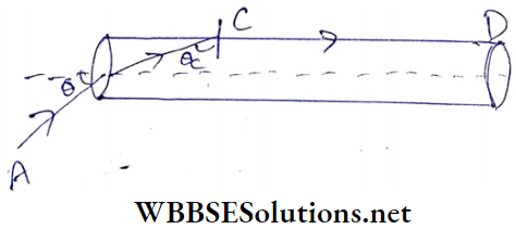
Example 9.  A transparent solid cylindrical rod has a refractive Index of. It Is surrounded by air. A light ray Is Incident at the midpoint of one end of the rod.  Determine the incident angle 8 for which the light ray grazes along the wall of the rod

Class 12 Physics Unit 6 Optics Chapter 2 Refraction Of Light Light Ray Grazes Along The Wall Of The Rod

Solution:

For refraction of light at point B, we can write by applying Snell’s law

1 × sin θ = μ sin r

[where μ is the refractive index of the solid material)

or, sin θ = \(\frac{2}{\sqrt{3}} \sin r\) ……………………… (1)

The light ray BC is incident on point C making critical angle θc and propagates along CD

Thus, from Snell’s law,

μ = \(\frac{1}{\sin \theta_c}\)

Or, \(\theta_c=\sin ^{-1}\left(\frac{1}{\mu}\right)\)

=\(\sin ^{-1}\left(\frac{\sqrt{3}}{2}\right)\)

= 60°

r = 180°- (60° + 90°) = 30°

Hence from equation (1), we can write

θc = \(\frac{2}{\sqrt{3}} \sin 30^{\circ}=\frac{1}{\sqrt{3}}\)

Or, \(\sin ^{-1}\left(\frac{1}{\sqrt{3}}\right)\)

Class 12 Physics Unit 6 Optics Chapter 2 Refraction Of Light Snells Law

Examples of Total Internal Reflection

A test tube dipped in water: A glass test tube half filled with water is held obliquely in a beaker containing water

The empty portion of the Immersed test tube appears shining if It is seen from above. This happens due to the total internal reflection of light. For the empty portion of the tube, the light goes from a denser to a rarer medium. Rays which are incident at angles greater than the critical angle of glass and air (48.5°) arc are reflected. So this portion of the glass appears shining.

Class 12 Physics Unit 6 Optics Chapter 2 Refraction Of Light A Test Tube Dipped In Water

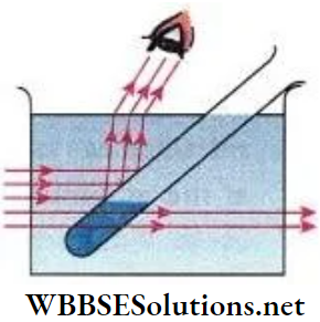
A portion of the tube filled with water does not glow because here light enters water In test tube from water in a beaker. Thus, total internal reflection does not occur here. In this discussion, we do not take into account the existence of the glass wall of the tube due to its negligible thickness.

A metal ball coated wHb lampblack Immersed In water:

If a metal ball coated will lampblack Is Immersed in water, the ball appears shining. Due to the coating of the lamp¬ black. a thin layer of air surrounds the surface of the ball. Rays incident at an angle greater than the critical angle of water and air, are reflected. The ball appears shining when the reflected rays reach the eyes of the observer.
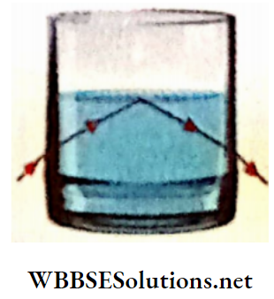
Glass tumbler full of water:

A glass tumbler full of water Is held above eye level. If the upper surface of water In the tumbler is seen from any one side, the surface appears shining. Rays coming from the side of the tumbler are incident on the surface of the separation of water and air. Hence total internal reflection takes place at particular angles of slantness and the surface of the water appears shining.

Class 12 Physics Unit 6 Optics Chapter 2 Refraction Of Light Glass Tumbler Full Of Water

Air bubbles:

The air bubbles rising through the water look shiny. Rays travelling through water are incident on the surface of the air bubbles. Those rays which are incident at angles greater than the critical angle are reflected. When these reflected rays reach the eyes of the observer, the hubbies appear shining. For the same reason, air bubbles existing In paper weights appear to be shining

Natural Examples Of Total Internal Reflection

Mirage: It Is an optical Illusion brought about by total internal reflection. There are two types of mirage, one observed in hot regions and the other observed In extremely cold regions.

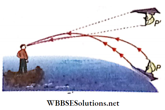
1. Inferior mirage or mirage in the desert:

People travelling through the desert sometimes see water at a distant place which is an optical illusion, called an inferior mirage, or simply, a mirage.

During daytime, the lower regions of the atmosphere become hot¬ ter than the upper regions. So density of air in the lower regions is less than that in the higher regions. Let us consider the atmo¬ sphere to be made up of layers of air, one above the other. A ray of light starting from a distant tree (P) and travelling downward happens to be going from a denser to a rarer medium.

Class 12 Physics Unit 6 Optics Chapter 2 Refraction Of Light Inferior Mirage Or Mirage In Desert

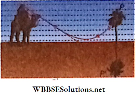
So its angle of incidence at consecutive layers goes on increasing gradually till it exceeds the critical value when it is reflected due to total internal reflection. The traveller sees an inverted virtual image (P’) of the tree. Secondly, due to continuous temperature changes, there exists a temperature gradient in the layers which undergo a continuous change of density and hence in the refractive index as well. So the path of the rays coming through the layers of air is also continuously changing. Hence to the traveller, the image of the tree appears to be swaying. This completes the illusion of a pond lined with trees.

 2. Superior mirage or mirage in cold countries:

In cold countries, the temperature of air In the lower regions is lower than that of the upper region. So the density of air in the lower region is greater than that of the upper region. A ray of light starting from an object (P) travelling upwards, finds itself going from denser to rarer medium

So its angle of incidence at consecutive layers of air gradually increases till it reaches the critical value. Then it is reflected due to total internal reflection. To an observer, the ray appears to come from a point above, thus giving the impression that an inverted object (P’) is floating in the air which is an optical illusion. This phenomenon is called a superior mirage

Class 12 Physics Unit 6 Optics Chapter 2 Refraction Of Light Superior Mirage

View of an observer inside water:

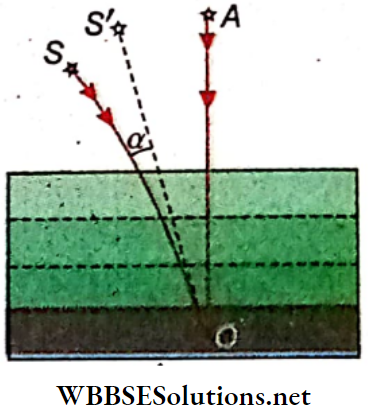
To the eye of an observer or a fish Inside water, all objects above water appear to exist in n cone of semi-vertical angle <19° which Is the critical angle of water and air. This happens due to total Internal reflec¬ tion of light.

If a ray of light travelling from a denser medium is Incident at the critical angle, the refracted ray grazes the surface of separation. Conversely, if a ray of light travelling from a rarer medium is incident at an angle of 90°, the angle of refraction In the denser medium becomes equal to the critical angle. The critical angle of water and air is 49°. So if a ray of light S1A coming from the rising sun AS1, along the surface of water reaches eye E along the direction AE, then the angle of refraction in water becomes 49°

As the eye cannot follow ray AS1, an observer inside water will sec the rising sun along the line EAC and this line will make an angle of 49° with the line OE. Similarly, the setting sun S2 will be seen along the line EBD and this line also will make an angle of 49° with the line OE. So all the objects above water appear to exist in a cone of angle 98° to the eye of a fish or observer underwater.

Class 12 Physics Unit 6 Optics Chapter 2 Refraction Of Light Eye Of A fish Or Observe Under Water

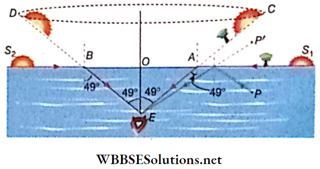
It Is to be noted that the sun describes an arc of 180° to earthbound observers but to the eyes of a fish it describes an arc of 98°.

1.  Surface of water to the eye of an observer inside water:

The diameter of the circular base of the cone AEB is AB. If an observer keeping his eye on E looks at the circular section of water, he can see any object lying above water. But If the observer looks at the rest of the portion of water other than the circular portion, then

  1. He cannot see any object above water, rather
  2. He can see the images of the objects inside the water.

Reason explaining 1st Incident:

Any ray of light coming from outside water can reach point E only through the circular section but cannot reach point E if it comes through die remaining portion.

Reason explaining 2nd Incident:

Suppose the ray of light emerging from the object situated In water, reaches die point E after reflection from the surface of water. This reflection will take place from the surface of the water excluding the circular portion.

This reflection will be a total reflection. For example, if a ray of light from the object P situated inside water, is incident on the surface of water, the angle of incidence exceeds 49°. So, the ray after total reflection from the surface of the water reaches the eye of the observer and he observes the dead object, at P’.

So to the observer situated inside water, the surface of the water appears as a mirror with a circular hole in it, because he sees the objects situated outside water through the circular section and sees the images of the objects inside water in die remaining action of the surface of the water. The radius of the circular hole is OA or OB.

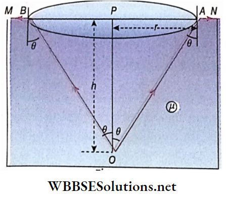
2. Determination of the radius of the hole:

Let the radius of the hole =OA = OB = r and OE – h. If the critical angle is θ then ∠OEA = Qc

⇒ \(\tan \theta_c=\frac{O A}{O E}=\frac{r}{h}\)

Or, \(r=h \tan \theta_c=h \frac{\sin \theta_c}{\cos \theta_c}\)

= \(h \frac{\sin \theta_c}{\sqrt{1-\sin ^2 \theta_c}}\)

Since ( sin \(\theta_c=\frac{1}{\mu}\))

= \(h \frac{\frac{1}{\mu}}{\sqrt{1-\frac{1}{\mu^2}}}\)

r = \(\frac{h}{\sqrt{\mu^2-1}}\)

Sparkling of diamond:

Diamond is notable for its sparkle and shine. This characteristic of a diamond is based on total internal reflection. The refractive index of a diamond is 2.42 and its critical angle relative to air is only 24.4°. This value is quite small as compared to other pairs of media.

Therefore, there is a high probability of total internal reflection in the case of diamond. If the diamond is cut properly, it will have a large number of faces. Ray of light entering through one face undergoes total internal reflection at several faces. As the rays of light enter through many faces and are confined inside they emerge together through only a few faces, these faces appear to sparkle and shine

Transmission of Light through Optical Fibre

Optical fibre:

A beam of light can be sent from one place to another through an optical fibre made of glass, quartz or optical-grade plastic, by following successive total internal reflections. As water can be sent from one place to another through a hollow pipe, a fibre can allow light to flow through it from one place to another. Hence, an optical fibre is often loosely called a light pipe.

Construction and principle of action:

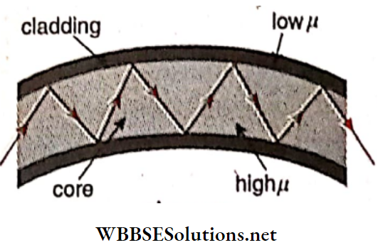
An optical fibre is a long and very thin pipe. Its diameter is about 10 × 10-6 metres. The internal section of the die pipe is called the core. It is a die core through which light travels from one point to another. Above the core, there is a coating of a substance having a refractive index less than that of the core. This coating is called cladding.

A ray of light entering die fibre through one face undergoes successive total internal reflections at the surface of separation of core and cladding and emerges through the other face [Fig. 2.38].: As total internal reflection of light takes place inside a fibre, the intensity of the light remains almost the same.

Class 12 Physics Unit 6 Optics Chapter 2 Refraction Of Light Constraction And Principle Of Action

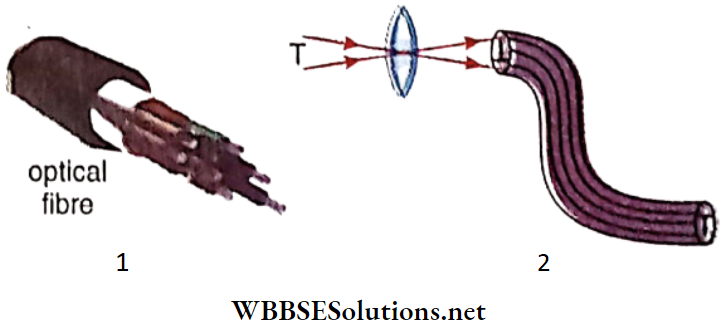
The image of a large object cannot be sent through a single fibre. In that case, bundles of fibres or cables of fibres are used. A cable contains about a thousand fibres. The image of an object is focused on one end of the bundle. If the order of die fibres is properly maintained, the image obtained at the other end will be an exact reproduction. In, the letter ‘T’ has been focussed at one end of the die bundle and an exact image of ‘T’ has been obtained. Light rays from the different portions of ‘T’ travel through the different fibres and form a die image at the other end

Class 12 Physics Unit 6 Optics Chapter 2 Refraction Of Light Different Fibers

Application of optical fibre:

  • Optical fibres are extensively used in medical science and the field of communication.
  • These are used to study the interior parts of the body which are inaccessible to the bare eye, for example, lungs, tissues, intestines etc. It can be used to transmit high-intensity laser light inside the body for medical purposes.
  • These are used for sending signals from one place to another. This signal is mainly digital. It is information that the signal carries.
  • This information is used in telephone, television, fax, computer etc. It is to be noted that, different digital signals may be sent through the same fibre at the same time, without any chance of overlapping.
  • So many times it is needed to collect samples inside from human body to identify disease. For this purpose, optical fibre is used. Besides, optical fibre is used for operation inside the human body. Thus, in most cases, no major excising is needed outer part of the body

Advantages of optical fibre over copper wire:

  • Comparatively less power Is required to send a signal,
  • The loss in energy Is much less
  • The capacity of carrying information is approximately times.
  • There exists no influence of any external electromagnetic wave signal.
  • Electrical resistance is much more.
  • It is very light.
  • killVelocity of the signal is very fast (approximately equal to that of light in vacuum).
  • The possibilities of the illegal usage of the signal are very low.

Optics

Refraction Of Light  Transmission of Light through Optical Fibre Numerical Examples

Example 1. A point source of light is placed at a depth of h below the calm surface of the water. From the source, light rays can only be transmitted to air through a definite circular section,

  1. Draw the circular section of the surface of the water by ray diagram and mark its radius r.
  2. Determine the angle of incidence of a ray of light incident at any point on the circumference of the circular plane. [Given: refractive index of water,\(\frac{4}{3}\) = 48°36′ = sin-1 0.7501 ]
  3. Show that r= \(\frac{3}{\sqrt{7}} h\)

Solution:

Let MN be the open surface of water. O is the source of light at a depth h below the surface of water. Light rays incident on the surface of the water from 0 at angles less than critical angle transmit in air after refraction. At points A and B the light rays are incident at angles equal to the critical angle (θ). So the refracted rays at these two

Class 12 Physics Unit 6 Optics Chapter 2 Refraction Of Light Refracted Rays

Points graze along the surface of separation. So the light rays will transmit outside water only through the circular section of radius r =  AP = PB.  If the rays are Incident on the surface of water excluding this circular section, the»7 will be reflected from (be surface of the water and will return to water,

Let the angle of Incidence be θ.

⇒ \(\sin \theta=\frac{1}{a^{\mu_w}}=\frac{1}{\mu}=\frac{3}{4}\)

= sin 48°36′ or, = 48° 36′

From the triangle AOP,

⇒ \(\tan \theta=\frac{A P}{O P}=\frac{r}{h} \quad \text { or, } \frac{\sin \theta}{\cos \theta}=\frac{r}{h}\)

Or,\(\frac{\frac{1}{\mu}}{\sqrt{1-\frac{1}{\mu^2}}}=\frac{r}{h}\)

∴ \(\sin \theta=\frac{1}{\mu}\)

Or, \(r=\frac{h}{\sqrt{\mu^2-1}}=\frac{h}{\sqrt{\frac{16}{9}-1}}=\frac{3}{\sqrt{7}}\)

Example 2.  The water in a pond has a refractive Index| of light and is placed 4 m below the surface of the water. Calculate the minimum radius of an opaque disc that needs to be floated on water so that light does not come out.
Solution:

Minimum radius of the opaque disc,

r = \(\frac{h}{\sqrt{\mu^2-1}}=\frac{4}{\sqrt{\left(\frac{5}{3}\right)^2-1}}\)

= \(\frac{4}{\frac{4}{3}}\)

= 3m

Example 3. Shows a longitudinal cross-section of an optical fibre made of glass with a refractive index of 1.68. The pipe is coated with a material of a refractive index of 1.44. What is the range of the angles of the incident rays with the axis of the pipe for which total reflection inside the fibre can take place?
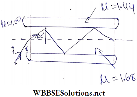
Class 12 Physics Unit 6 Optics Chapter 2 Refraction Of Light Longitudinal Cross Section

Solution:

The refractive index of the outer coating concerning the glass pipe

⇒ \(g_g \mu_c=\frac{a^{\mu_c}}{a^{\mu_g}}=\frac{1.44}{1.68}\)

If the critical angle for the total reflection is θ, then

sinθ = \(\frac{1}{c^{\mu_g}}\)

= \(\frac{1.44}{1.68}\)

= 0.857 or, 59°

Thus’ total reflection takes place when i’ > 59° or when r < rmaxwhere rmax= 90° – 59° = 31°

So if the maximum angle of incidence on the fibre is imax then,

sin imax  = μgsir r max= 1.68 sin 31° = 0.865

Imax  = 60°

So, the range of the angles of incidence for total internal reflection inside the fibre is from 0° to 60°.

Example 4. In which direction will the sun appear to set if the observer is inside the water of a pond? Refractive index of water, μ – 1.33.
Solution:

For a setting sun, the incident rays graze along the surface of the water, i.e., angle of incidence = 90°

∴ According to Snell’s law

μw= \(\frac{\sin i}{\sin r} \)

Or,   1.33 \(=\frac{\sin 90^{\circ}}{\sin r}\)

sir r  = \( \frac{1}{1.33}\)

= 0.7518

= sin 48.75°

r = 48.75°

Therefore, to see the setting sun the observer in water should look at an angle of 48.75° with the normal.

Optics

Refraction Of Light Atmospheric Refraction

Apparent position Of a star: The whole atmosphere surrounding the earth may be supposed to be divided into different horizontal layers. As the height above the earth’s surface increases, the density of the air decreases. Due to this, the refractive index of air also decreases with the increase in altitude. For this reason, the ray from a star S (say) proceeding towards the earth’s surface cannot travel straight but continually bends towards the normal at the surface of separation due to refraction as it penetrates from rarer to denser layers

This ray after several refractions reaches the observer at O. But our vision cannot follow the curved path OS. A tangent OS’ is drawn on OS at O . So, the observer sees the star at S’. This phenomenon is called atmospheric refraction.

Class 12 Physics Unit 6 Optics Chapter 2 Refraction Of Light Atmospheric Refraction

Visibility of the sun before sunrise and after sunset:

The diameter of the sun subtends an angle of 0.5° at the eye of an observer on Earth. This value is equal to the deviation of sun¬ light due to atmospheric refraction, when at the horizon. So, the sun appears to just touch the horizon during sunset and sunrise when it is actually below it. What we see therefore is the raised image of the sun, formed due to atmospheric refraction. As a result, we see the sun a few minutes after sunset or before sunrise. Now, the sun covers a distance equal to its diameter in 2 min.

So, the sun becomes visible another 2 min earlier at sunrise and also remains visible for another 2 min after the actual sunset. Consequently, 4 min are added to the length of a day. This value is valid for observations from the equatorial region. At higher latitudes, this time increases

The oval shape of the sun when It Is near the horizon:

During sunrise or sunset, the lower edge of the sun remains nearer to the horizon than its upper edge. So, the rays coming from the lower edge of the sun are incident on an atmospheric layer at a larger angle than that for the rays coming from its upper edge. As the refracting angle increases with the increase of the incident angle, the rays coming from the lower edge bend more than the others due to multiple refractions at different atmo¬ spheric layers. As a result, the vertical diameter of the Sun appears to be reduced whereas the horizontal diameter remains unaffected.

Twinkling of Stars:

Due to atmospheric refraction, we see the stars twinkle. Light rays from the stars situated far and far away from us come to our eyes passing through various layers of air. The temperature of the layers does not remain constant and changes continuously. So the density of the various layers also. changes.

Again the refractive index of the layers changes with the change of density. So, when the rays of light from a star come to our eyes, the direction of the path of the rays changes continuously. As a result, the amount of light reaching our eyes also changes continuously. It seems as if the brightness of the stars is changing. So the stars appear twinkling.

As the planets are nearer to us than the stars, more amount of light comes to us. Therefore, the change in brightness of the planets due to changes in the refractive index of various layers of air is negligible. We cannot detect it with our eyes. So it appears that the planets are emitting light steadily.

Optics

Refraction Of Light Thin Prism

Thin Prism Definition:

The prism, whose refracting angle is very small (not more than 10°), is called a thin prism.

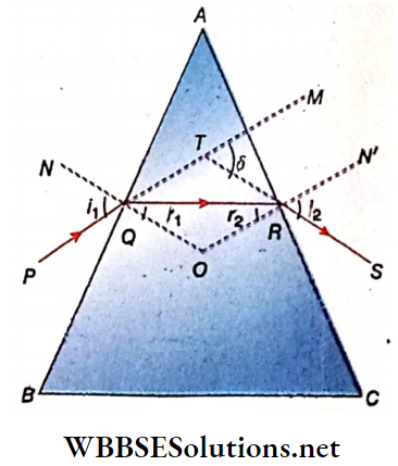
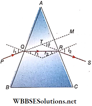
Deviation produced by a thin prism:

ABC is a thin prism. A ray PQ is incident on the refracting face AB nearly normally. For nearly normal incidence, i1 ≈ 0, i2≈0. If n is the refractive index of the material of the prism, then

μ = \(\frac{\sin i_1}{\sin r_1}=\frac{i_1}{r_1} \quad \text { or, } i_1=\mu r_1\)

And \(\mu=\frac{\sin i_2}{\sin r_2}=\frac{i_2}{r_2} \quad \text { or, } i_2=\mu r_2\)

Or,

So, the deviation of the ray

⇒ \(\delta=i_1+i_2-A=\mu r_1+\mu r_2-A=\mu\left(r_1+r_2\right)-A\)

= μA – A

Since = r1+r2 = A

= (μ- 1)

Class 12 Physics Unit 6 Optics Chapter 2 Refraction Of Light Deviation Produced By A Prism

Again, if the ray PQ is incident on the face AB normally, then

i1= r1 = 0. So, A = r2
.
Therefore, the deviation of the ray,

δ = i1 + i2 – A = μr2-A =μA-A = (μ -1 )A

So, for normal and nearly normal incidence, the deviation of the array in a thin prism, δ = (μ-1)A

Thus it is seen that for normal or nearly normal incidence, the deviation of a ray in a thin prism depends only on the refract¬ ing angle of the prism and the refractive index of its material but not on the angle of incidence. So if the angle of the incidence is small, the deviation of a ray in the case of a thin prism remains constant.

Optics

Refraction Of Light Thin Prism Numerical Examples

Example 1. A very thin prism deviates a ray of light through 5°. If the refractive index of the material of the prism is 1.5, what is the value of the angle of the prism?
Solution:

The angle of deviation for a thin prism,

δ = (μ-1)A

Here  δ = 5° and μ = 1.5

Therefore from equation (1) we get,

5° = (1.5 -1)A or, A = 10°

Example 2. A prism haying refracting angle 4°. Is placed in the air. Calculate the angle of deviation of a ray incident nor¬ mally or nearly normally on It. The refractive index of the material of the prism| = \(\frac{3}{2}\)
Solution:

The refracting angle of the prism, A = 4°. So it is a thin prism. We know that the deviation of a ray in a thin prism for. normal or nearly normal incidence is given by,

⇒  \(\delta=(\mu-1)\)A

⇒ \(\delta=\left(\frac{3}{2}-1\right) \times 4^{\circ}\)

= 2°

Example 3. A thin prism with a refracting angle of 5° and having refractive index of 1.6 is kept adjacent to another thin prism having a refractive index of 1.5 such that one is inverted concerning the other. An incident ray falling vertically on the first prism passes through the second prism without any deviation. Calculate the refracting angle of the second prism.
Solution:

According to the condition,

1– 1)A2 = (μ2– 1)A2

(1.6-1) × 5° = (1.5-1)A2

Or, A2 =\(\frac{0.6 \times 5^{\circ}}{0.5}\)

So the refracting angle of the second prism = 6°

Limiting Angle of a Prism for No Emergent Ray

A ray of light incident on a refracting surface of a prism may not emerge from the second refracting surface. It depends on the refracting angle of the prism. Every prism has a limiting value of its refracting angle. Light can emerge from the prism if the angle of the prism is equal to or less than this critical value, otherwise, no light can emerge from the prism.

Class 12 Physics Unit 6 Optics Chapter 2 Refraction Of Light Limiting Angle Of A Prism For No Emergent Ray

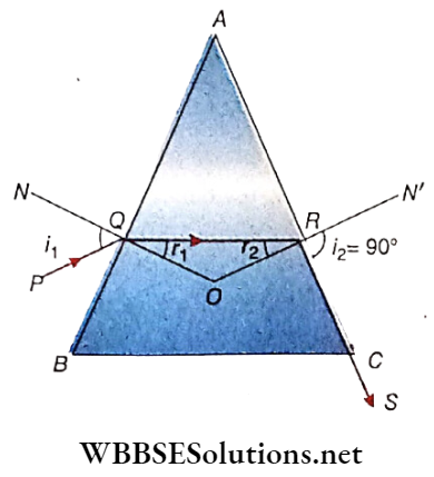
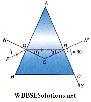
Let ABC be the principal section of a prism  PQRS is the path of a ray through the prism placed in the air where ray RS grazes along the second face AC.

Let the angles of incidence and refraction at the face AB be i1 and r1 respectively and the corresponding angles at the face AC be r2 and i2, where i2 = 90°.

So, r2 = θc, the critical angle between glass and air. If the refracting angle of prism A is equal to the limiting angle, then the ray incident at an angle of incidence fj to the face AB of the prism makes a grazing emergence along the second refracting surface AC

A= r1+r2 ……………….(1)

For refraction at Q

⇒ \(\sin i_1=\mu \sin r_1 \quad \text { or, } r_1=\sin ^{-1}\left(\frac{\sin i_1}{\mu}\right)\)

For refraction At R,

⇒ \(\sin 90^{\circ}=\mu \sin r_2 \quad \text { or, } r_2=\sin ^{-1}\left(\frac{1}{\mu}\right)\)

Or, \(\theta_c=\sin ^{-1}\left(\frac{1}{\mu}\right)\)

From equation (1) we get, A = \(A=\sin ^{-1}\left(\frac{\sin i_1}{\mu}\right)+\sin ^{-1}\left(\frac{1}{\mu}\right)\) …………. (2)

Special cases:

Limiting angle of the prism for normal incidence on the first face: When ray, PQ is incident on the face AB normally, then fj = 0. In this case, if the emergent ray grazes along the surface AC then from equation (2) we get,

A = \(\sin ^{-1}\left(\frac{\sin 0}{\mu}\right)+\sin ^{-1}\left(\frac{1}{\mu}\right)=\sin ^{-1}\left(\frac{1}{\mu}\right)=\theta_c\)

Hence, the ray can emerge from the prism through its second surface till the refracting angle of the prism remains less than its critical angle. But as the refracting angle of the prism becomes greater than its critical angle, no ray emerges from the surface AC. Then the face AC acts as a total reflecting surface.

Limiting angle of the prism for grazing incidence on the first face:

For grazing incidence on the face AB, i1 = 90° Then from equation (2) we get

A = \(=\sin ^{-1}\left(\frac{\sin 90^{\circ}}{\mu}\right)+\sin ^{-1}\left(\frac{1}{\mu}\right)\)

= \(\sin ^{-1}\left(\frac{1}{\mu}\right)+\sin ^{-1}\left(\frac{1}{\mu}\right)=2 \sin ^{-1}\left(\frac{1}{\mu}\right)=2 \theta_c\)

So, if the refracting angle of the prism is greater than 20C and if a ray is incident on the face AB grazing the surface, then it will be reflected from the face AC. It means the ray will not emerge in the air through the face AC. Hence, no emergent ray will be obtained.

Thus, from the above discussions we conclude that for any incidence no ray can emerge from the prism If the angle of the prism is greater than twice the critical angle for the material concerning the surrounding medium.

Optics

Refraction Of Light Limiting Angle Of Incidence For No Emergent Ray From A Given Prism

Just like a prism has a limiting refracting angle for no emergent ray, a prism with a definite refracting angle also possesses a limiting angle of incidence for no emergent ray from it. If the angle of incidence i1 becomes less than this limiting incident angle, then there will be no corresponding emergent ray.

Let ABC be the principal section of a prism. The ray of light PQ is incident at Q on the face AB. After refraction through the prism, the emergent ray RS grazes the second face AC of the prism.

Class 12 Physics Unit 6 Optics Chapter 2 Refraction Of Light Limiting Angle Of Incidence For No Emergent Ray From A Given Prism

Let the angles of incidence and refraction at the face AB be i1 and r1 the corresponding angles at the face AC be r2 and i2 respectively. Here, i2 = 90° .

Now, the angle of the prism, A = r1 + r2 – constant.

From, A = r1 + r2; we get, r2 = A – r1 , reduces with the decrease of it. Again, r1 increases with the decrease of r1

Now, if r2 is greater than θc the ray QR is reflected from the face AC inside the prism and it does not emerge in the air.

So when r1 = θc then i1 = limiting angle of incidence.

If μ is the refractive index of the material of the prism then

⇒ \(\sin \theta_c=\frac{1}{\mu}\)

⇒ \(\cos \theta_c=\sqrt{1-\sin ^2 \theta_c}=\sqrt{1-\frac{1}{\mu^2}}=\frac{\sqrt{\mu^2-1}}{\mu}\)

Considering the refraction of the ray at Q we have,

⇒ \(\cos \theta_c=\sqrt{1-\sin ^2 \theta_c}=\sqrt{1-\frac{1}{\mu^2}}=\frac{\sqrt{\mu^2-1}}{\mu}\)

= \(\cos \theta_c=\sqrt{1-\sin ^2 \theta_c}=\sqrt{1-\frac{1}{\mu^2}}=\frac{\sqrt{\mu^2-1}}{\mu}\)

= \(\sin i_1=\mu \sin r_1=\mu \sin \left(A-r_2\right)\)

Since A = r1+r2

= \(\mu \sin \left(A-\theta_c\right)=\mu\left[\sin A \cos \theta_c-\cos A \sin \theta_c\right]\)

= \(\mu\left[\sin A \cdot \frac{\sqrt{\mu^2-1}}{\mu}-\cos A \cdot \frac{1}{\mu}\right]\)

= \(\mu\left[\sin A \cdot \frac{\sqrt{\mu^2-1}}{\mu}-\cos A \cdot \frac{1}{\mu}\right]\)

= \(\sin A \sqrt{\mu^2-1}-\cos A\)

Or, i1 = \(i_1=\sin ^{-1}\left[\sin A \sqrt{\mu^2-1}-\cos A\right]\)

This is the limiting angle of incidence. If the angle of incidence is less than this limiting angle, no ray will emerge from the second face of the prism

Optics

Refraction Of Light Limiting Angle Of Incidence For No Emergent Ray From A Given Prism Numerical Examples

Example 1. To get an emergent ray from a right-angled prism its refractive index should not exceed \(\sqrt{2}\) —prove it.
Solution:

The condition of getting an emergent ray from a prism is that the refracting angle of the prism should be equal to or less than twice the value of the critical angle

A≤ 2θc Or, 90°≤ 2θ

Or, θc ≥ 45°

∴ sin θc ≥ sin 45° ,Or, sin θc ≥ \(\frac{1}{\sqrt{2}}\)

∴  \(\sin \theta_c=\frac{1}{\mu}\)

∴ \(\frac{1}{\mu}\frac{1}{\sqrt{2}}\)

Or, \(\sqrt{2}\)

Example 2. The refractive index of a prism having a refracting angle of 75° is \(\sqrt{2}\). What should be the minimum angle of incidence on a refracting surface so that the ray will emerge from the other refracting surface of the prism?

Solution: According to the question, the emergent angle is i2 = 90°.

So for refraction at the second face of the prism

μ = \(\frac{\sin i_2}{\sin r_2}=\frac{\sin 90^{\circ}}{\sin r_2}\)

Or, \(\sin r_2=\frac{1}{\mu}=\frac{1}{\sqrt{2}}\)

= sin 45°

Or, r2 = 45°

We, know A= r1 +r2

75= r1 + 45°

Or, r1 = 30°

For refraction at the first face

μ = \(\frac{\sin i_1}{\sin r_1}\)

Or, \(\sqrt{2}=\frac{\sin i_1}{\sin 30^{\circ}}\)

Or, \(\sin i_1=\sqrt{2} \times \frac{1}{2}=\frac{1}{\sqrt{2}}\)

= sin 45°

Or, i1 = 45°

The required angle of incidence = 45°

Example 3. Find the value of the limiting angle of incidence if the refractive index of the material of the prism is 1.333 and the angle of the prism is 60°
Solution:

Here, the refractive index of the material of the prism, mu = 1.333; the angle of the prism, A = 60°

⇒ \(i_L=\sin ^{-1}\left[\sin A \sqrt{\mu^2-1}-\cos A\right]\)

= \(\sin ^{-1}\left[\frac{\sqrt{3}}{2} \sqrt{(1.333)^2-1}-\frac{1}{2}\right]\)

= \(\sin ^{-1}(0.2633)\)

= 15.27°

Example 4. The refracting angle of the prism is 60° and its refractive J index is Jl. What should be the minimum angle of | incidence on the first refracting surface so that the ray | can emerge somehow from the second refracting our face?
Solution:

Let i be the limiting angle of incidence, then

sin i = \(\sqrt{\mu^2-1} \cdot \sin A-\cos A\)

= \(\sqrt{\frac{7}{3}-1} \cdot \sin 60^{\circ}-\cos 60^{\circ}\)

= \(\frac{2}{\sqrt{3}} \cdot \frac{\sqrt{3}}{2}-\frac{1}{2}\)

= \(1-\frac{1}{2}=\frac{1}{2}\)

i = 30

Example 5. The refractive index of the material of a prism is \(\)  and the refracting angle is 90°. Calculate the angle of minimum deviation and the corresponding angle of incidence. Show that the limiting angle of incidence for getting emergent ray is 45°
Solution:

Here, the refractive index of the material of the prism,

M = \(\sqrt{\frac{3}{2}}\)

The angle of prism A =  90°

μ = \(\frac{\sin \frac{A+\delta_m}{2}}{\sin \frac{A}{2}}\)

Or, \(\sqrt{\frac{3}{2}}=\frac{\sin \frac{A+\delta_m}{2}}{\sin 45^{\circ}}\)

⇒ \(\sin \frac{A+\delta_m}{2}=\sqrt{\frac{3}{2}} \times \frac{1}{\sqrt{2}}=\frac{\sqrt{3}}{2}\)  = sin 60°

⇒  \(\frac{A+\delta_m}{2}\)  = 60°

Or, A + δm = 120°

δm = 120° – 90° = 30°

For minimum deviation, i1= i2

δm = i1+ i2 -A

30° = 2i1 – 90

Or, 2i1 = 120°

Or, i2= 60°

Or minimum deviation angle of indecency = 60

To obtain the emergent ray I be the limiting angle of incidence. Then

sini = \(\sqrt{x^2-1} \sin x-\cos 4\)

= \(\sqrt{\frac{3}{2}-1} \cdot \sin 90^{\circ}-\cos 90^{\circ}=\frac{1}{\sqrt{2}}\)

= sin 45°

= 45°

Example 6. The refractive index of a prism is \(\sqrt{2}\). A ray of light is incident on the prism grazing along one of its refracting surfaces. What should be the limiting angle of the prism for no emergent ray from the other face?
Solution:

If The limiting angle of the prism for no emergent ray is A, then

A = \(2 \sin ^{-1} \frac{1}{\mu}\)

= \(2 \sin ^{-1} \frac{1}{\sqrt{2}}=2 \times 45^{\circ}\)

= 90°

Optics

Refraction Of Light Conclusion

1. When a ray of light enters a medium from another medium through the interface of the two media, then the path of the rav changes its direction and this phenomenon is known as refraction of light.

2. Laws of refraction:

  • The incident ray, the refracted ray and the normal to the refracting surface at the point of incidence lie on the same plane.
  • The sine of the angle of incidence bears a constant ratio to the sine of the angle of refraction. The value of this constant depends on the nature of the pair of media concerned and the colour of the incident light.

3. Relative refractive index:

When a ray of light is refracted from a medium a to another medium b then the ratio of the sine of the angle of Incidence to the sine of the angle of refraction is called the refractive index of the medium b concerning the medium a. This refractive index is called the relative refractive index.

4. Absolute refractive index:

When a ray of light is refracted from the vacuum to any other medium then the ratio of the sine of the angle of incidence to the sine of the angle of refraction is called the absolute refractive index of that medium.

5. Critical angle:

When a ray of light is refracted from a denser medium to a rarer medium than for a particular angle of incidence in the denser medium, the angle of refraction in the rarer medium is 90° i.e., the refracted ray grazes along the interface of the .two media. Then that particular angle of incidence is called the critical angle for the pair of media.

6. Total internal reflection:

While passing from a denser medium to a rarer medium, if a ray of light is incident on the surface of separation between the angle greater than the critical angle for the two media involved, the ray of light is reflected to the denser medium without undergoing refraction in the rarer medium. This phenomenon is known as the total internal reflection of light.

Through optical fibres tight rays can be transmitted from one place to another in the straight or curved path by successive total internal reflections. f If a ray of light from a rarer medium is incident on a prism of denser medium then after refraction through the prism, the ray of tight bends towards the base of tyre prism. -f In the case of reflection or refraction, the change of direction of tight is called deviation.

4- Minimum deviation:

For any prism, there is a certain angle of incidence for which the angle of deviation becomes minimum or the least. This angle of deviation is called the angle of minimum deviation for the prism.

At minimum deviation, the angle of incidence becomes equal to the angle of emergence.

5. Thin prism:

If the refracting angle of a prism is very small (not more than 10° ) then it is called a thin prism.

6. Total reflecting prism:

If the principal section of a prior made of crown glass is a right-angled isosceles triangle then the prism makes a total Internal reflection of light for any incidence on it hence this type of prism is called a total reflecting prism.

7. During the refraction of light, the velocity, intensity and wavelength of light change but its frequency and phase remain constant.

8. If there is a parallel glass slab in the path of light then Ugh rays remain undefeated after refraction through it but lateral displacement of light rays will occur.

9.  \(\frac{\sin i}{\sin r}={ }_a \mu_b=\frac{\mu_b}{\mu_a}\)

μa = absolute refractive index of medium a, nb = absolute refractive index of medium b, afib = relative refractive index of medium b concerning the medium a.

10.  \(\frac{\sin i}{\sin r}={ }_a \mu_b=\frac{\mu_b}{\mu_a}\)

[ va = velocity of light in the medium a, vb= velocity of tight in the medium b ]

⇒  \(\mu=\frac{c}{v}\)

[n = absolute refractive index of a medium, v = velocity of light in that medium, c = velocity of tight in vacuum]

[v= – frequency of the wave, A = wavelength]

11. \(a^{\mu_b}=\frac{v_a}{v_b}\)

The relation between (i and A given by scientist Cauchy

12. \(\mu=\frac{c}{v}\)

Deviation of a ray of tight due to refraction,

= i~r [i = angle of incidence, r = angle of refraction]

13. Lateral displacement of a ray of tight after suffering refraction through a parallel plate glass slab

= \(t \sin i_1\left[1-\frac{\cos i_1}{\sqrt{\mu^2-\sin ^2 i_1}}\right]\)

[where, i- the angle of incidence on the front surface of the tin slab, t = thickness of the slab, (J- = refractive index of the material of the slab]

If the angle of incidence ij is very small then lateral displacement = \(t i_1\left(1-\frac{1}{\mu}\right)\)

14. General formula ofSnell’s law:

μ1 sin= μ2sin2 =  μ3 sin3 = ………………. = μ3 sin i3

15. The apparent position of an object due to refraction:

The refractive index of rarer medium =; refractive index c denser medium = μ1

1. If the object is in a denser medium and the observer is in: a rarer medium:

The refractive index of the denser medium with respect to the rarer medium real depth of the object from
= \(=\frac{\text { the surface of separation }(d)}{\text { apparent depth of the object from the surface of separartion}}\)

= \(\frac{\mu_2}{\mu_1}\)

2. If the object Is In the rarer medium and the observer is in a denser medium: The refractive index of the denser medium concerning the rarer medium apparent height of the object from

= \(\frac{\text { the surface of separation }\left(d^{\prime}\right)}{\text { real height of the object from the surface of separation (d)}}\)

16. The refractive index of glass

=\(\frac{\text { real thickness of a thick mirror }}{\text { apparent thickness of a thick mirror }}\)

⇒ \(\frac{1}{b^{\mu_a}}=\frac{\mu_b}{\mu_a}\)

[where, A = r1+r2]

17. Deviation of a ray of light after refraction through a prism,

[i = angle of incidence on the first face of the prism, i’μa = angle of emergence from the second face to the prism, r1

= angle of refraction In the first face, = angle of incidence in the second face, A = refracting angle of the prism]

18. In case of minimum deviation, i1 = i2 = i (say)

r1 = r2 = r (say)

19. In that case, the minimum deviation, δ

m = 2i-r and A = 2r.

20. Relation between refractive index (fi) and minimum deviation (8m ) :

μ\(\frac{\sin \left(\frac{A+\delta_m}{2}\right)}{\sin \frac{A}{2}}\)

21. For the normal and nearly normal incidence of a ray of light, deviation in the case of a thin prism,

⇒ δ = (μ-1)A

22. Limiting the angle of a prism for no emergent light from a prism

⇒ \( \sin ^{-1}\left(\frac{\sin i_1}{\mu}\right)+\sin ^{-1}\left(\frac{1}{\mu}\right)\)

When iy = 0 , then A>θc; when iy = 90°, then A >2θc.

Limiting value of the angle of incidence in case of definite prism for no emergent light from it,

⇒\(i_1=\sin ^{-1}\left[\sin A \sqrt{\mu^2-1}-\cos A\right]\)

23. A ray of light passes through n number of media of refractive indices, μ1,  μ2, μ3, ……………….. μn respectively. The planes of the media are parallel. If the emergent ray from the n -th medium is parallel to the ray incident on the first medium, then μ1 = μ2

24. For a hollow prism, the angle of the prism is A ≠ 0 but the angle of deviation is δ = 0.

25. A container of depth 2d is half filled with a liquid of refractive index μ1 and μ2    the remaining half is filled with another liquid of refractive index When seen from the top, the apparent depth of the container is

⇒ \(d\left(\frac{1}{\mu_1}+\frac{1}{\mu_2}\right)\)

26. An observer is situated at a depth h in a water body. The water surface appears as a porous circular mirror to

 27. If a parallel plane glass slab of thickness t is kept in the path of a beam of converging rays, then the displacement of the intersecting point of the rays,

⇒ \(O O^{\prime}=x=\left(1-\frac{1}{\mu}\right) t\)

Class 12 Physics Unit 6 Optics Chapter 2 Refraction Of Light PArallel Plane Glass Slab Of Thickness

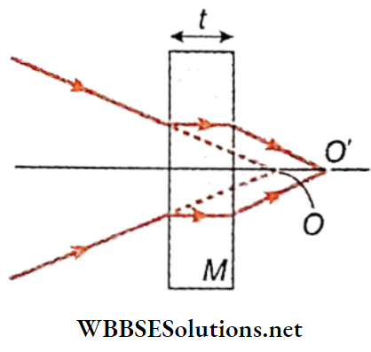
To transmit through a glass slab of thickness t and refractive index μ, time taken by light is, where c is the velocity of light in vacuum \(\frac{\mu t}{c}\)

Optics

Refraction Of Light Very Short Questions

Question 1. What is the angle of deviation due to the refraction of a ray of light incident perpendicularly on a refracting surface?
Answer: Zero

Question 2. Arrange the following media according to the increasing optical density Air, diamond, glass, water, glycerine.
Answer:

Air < Water < Glycerine < Glass < Diamond]

Question 3. Can the value of absolute refractive index of a medium be
Answer: No

Question 4. State the relation of velocity of light with refractive index
Answer:

⇒ \(\left[\mu=\frac{c}{v}\right]\)

Question 5. The refractive index of a medium depends on temperature’—is the statement correct or wrong?
Answer: Correct

Question 6. Arrange the following media according increasing velocity of light through them: vacuum, diamond, water, air, glass
Answer:

Diamond < Glass < Water < Air < Vacuum

Question 7. Does the velocity of light in a vacuum depend on

  1. Wavelength of light
  2. Frequency of light
  3. Intensity of light?

Answer: No

Question 8 If water is heated, how refractive index it will change?
Answer: Decrease

Question 9. The refractive index of glass is 1.5. What is the velocity of light
Answer: [2 × 10⁸m/s].

Question 10. Can the relative refractive index of a medium concerning another be less than unity?
Answer: Yes

Question 11. The refractive index of a medium is a physical quantity having no dimension and no unit—is the statement true or
Answer: True

Question 12. A light ray of wavelength 4500 A enters a glass slab of refractive index 1.5, from the vacuum. What is the wavelength of light inside the slab?
Answer: 30000 A°

Question 13. For which colour of light is the refractive index of glass the minimum?
Answer: Red

Question 14. If the frequency of light increases will there be any change in the refractive index of the medium?
Answer: No

Question 15. For which colour of light is the refractive index of glass a maximum?
Answer: Violet

Question 16. Does the refractive index of glass depend on the colour of light? If so, how?
Answer: Yes, the refractive index increases with the decrease of wavelength

Question 18. When a ray of light is incident on a plane normally, then what is the value of the angle of refraction?
Answer: Zero

Question 17. If for refractive index of water relative to air is \(\), what will be the refractive index of air relative to water
Answer:

⇒ \(\frac{3}{4}\)

Question 18. When light travels from air to glass, how does its wavelength change? less than 1
Answer: Wavelength decreases

Question 19. The absolute refractive index of water and glass are \(\frac{4}{3}\) and \(\frac{3}{2}\). What is the ratio of velocity of light in glass and water?
Answer: [8:9]

Question 20. what is the value of the product of the refractive index of relative of the first medium and that of the first-second medium relative to the second medium?
Answer: 1

Question 21. For what angle of incidence the lateral shift produced by a parallel-sided glass plate is zero?
Answer: For i = 0

Question 22. For what angle of incidence the lateral shift produced by a parallel-sided glass plate is maximum?
Answer: For i = 90°

Question 23. what is the maximum lateral shift produced by a parallel-sided glass plate of thickness t?
Answer: t

Question 24. The bird descends vertically downwards in the direction of a pond during its flight. To a fish which is underwater and directly below the bird, what will be the apparent position of the bird?
Answer:

The bird’s apparent position will be slightly above its actual position i.e., the bird will appear higher up than it is

Question 25. An object lying inside a pond is viewed by a man from above (air) along a horizontal plane. Now if the man moves away from the object keeping his eyes along the same horizontal plane, how will the apparent depth of the object change?
Answer: Decrease along the caustic curve

Question 26. A transparent cube of glass of refractive index n and thickness ‘t is placed on a spot of ink drawn on white paper. When the spot is viewed from above (air) normally, the spot appears to shift through a distance of At towards the observer. What is the value of Δt?
Answer:

⇒ \(\left[\left(l-\frac{1}{\mu}\right) t\right]\)

Question 27. If a straight rod is held obliquely in water how does the immersed portion of the rod appear?
Answer: Refraction of light

Question 28. Multiple images are formed in a thick mirror. Which Image looks brightest?
Answer: Second images

Question 29. If a completely transparent object has to be made Invisible In a vacuum, what should be the value of its relative Index?
Answer: 1

Question 30. What Is the critical angle of light when passing from water \(\left(\mu \text { of water }=\frac{4}{3}\right)\)
Answer: 49

Question 31. For which colour of light is the critical angle between glass and air minimum?
Answer: Violet

Question 32. What are the factors of light which are responsible for creating mirages?
Answer: Refraction and total internal reflection]

Question 33. In which direction do we have to look to see the setting sun if we are underwater? (μw = 1.33)
Answer: At an angle of 49° with the normal drawn at the surface of the water]

Question 34. From sunrise to sunset, the sun subtends an angle of 180’ to our eyes. What will be the value of this angle to an observer underwater?
Answer: 98°

Question 35. Light passes through an optical fibre following which physical phenomenon?
Answer: Total internal reflection

Question 36. What is the approximate value of the refractive index of a diamond
Answer: 2.42

Question 37. what kind of image is formed in a desert by the formation
Answer: Virtual

Does critical depend on the colour of life

Question 38. The angular altitude at which we see a star is not its actual angular altitude’—is the statement true or false?
Answer: True

Question 39. The sun appears to be elliptical during sunset. What is the reason behind it?
Answer: Refraction of light

Question 40. Under what condition the angle of deviation of a refracted ray through a prism will be minimal?
Answer: If the angle of incidence and the angle of emergence are equal

Question 41. If the medium surrounding the four faces of a prism is denser an the entire material of the prism, then in which direction will the light rays bend when emerging from the prism?
Answer: It will bend upwards, towards the prism apex

Question 42. How can an inverted image be made erect by using a total reflecting prism?
Answer: By total internal reflection on the hypotenuse of a right-angled

Question 43. ‘When light travels from a rarer medium to a prism which is a denser medium, a light ray bends towards the base of the prism. Is the statement true or false?
Answer: True

Question 44. At the position of minimum deviation, what is the nature of the path of a light ray through a prism?
Answer: Symmetrical

Question 45. For a thin prism on what factor does the magnitude of the angle of deviation of light rays depend?
Answer: Angle of incidence

Question 47. what will be the angle of deviation of a ray of light incident normally on any smaller side of a total reflecting prism?
Answer: 90°c

Optics

Refraction Of Light Fill In The Blanks

Question 1. Which of the following_________________wavelength, frequency or velocity does not change during the refraction of light?
Answer: Frequency

Question 2. For any particular medium, the refractive index is greater If the wavelength of light is____________________ 
Answer: Small

Question 3. If μa,  μb and μc are the absolute refractive indices of three media then aμb × bμc  _________________________
Answer: aμc

Question 4. When a man stands inside a shallow pond the depth of water at that place appears___________________places appear comparatively___________________ and the depth of other 
Answer: Maximum, Less

Question 5. Critical angle of which pair of medium is lesser___________air and water or air and diamond
Answer: Air and Diamond

Question 6. We see the sun ___________________ a few minutes ___________________ sunset or sunrise
Answer: After, Before

Question 7. If a ray of light moves from a ___________________ medium to a ___________________, total internal reflection does not take place
Answer:
Rarer, Denser

 Optics

Refraction Of Light Assertion Reason Type

Direction: These questions have statement 1 and statement 2 of the four characters given below, choose t=the one that best describes the two statements

  1. Statement 1 is true, statement 2 is true, and statement 2 is a correct explanation for statement 1.
  2. Statement 1 is true, statement 2 is true, and statement 2 is not a correct explanation for statement 1
  3. Statement I is true, and statement 2 is false
  4. Statement 1 is false statement 2 is true

Question 1. 

Statement 1: The Greater the refractive index of a medium or denser the medium, the lesser the velocity of light In that medium

Statement 2: Refractive index is inversely proportional to velocity.

Answer: 1.  Statement 1 is true, statement 2 is true, and statement 2 is a correct explanation for statement 1.

Question 2.

Statement 1: The critical angle of the light passing from glass to is minimal for violet colour

Statement 2: The wavelength of violet light is greater than the light of other colours

Answer: 3. Statement I is true, and statement 2 is false

Question 3.

Statement 1: The twinkling of the star is due to the reflection of light

Statement 2: The velocity of light changes while going from one medium to the other.

Answer: 4. Statement 1 is false statement 2 is true

Question 4.

Statement 1: The relative refractive index of a medium can be less than unity.

Statement 2: The angle of incidence is equal to the angle of refraction

Answer: 3. Statement I is true, and statement 2 is false

Question 5.

Starement 1: When a ra> of light enters glass from atr. Its frequency changes

Sutrmem 2: The velocity of light in glass is less than that in oil.

Answer: 4. Statement 1 is false statement 2 is true

Question 6.

Statement 1: The refractive index of a medium Is Inversely proportional to temperature

Statement 2: Refractive index U is directly proportional to the density of the medium.

Answer: 2. Statement 1 is true, statement 2 is true, and statement 2 is not a correct explanation for statement 1

Question 7. 

Statement 1: The velocity of light rays* of different colours is the same. But the velocity of the light rays is different for anv another medium.

Statement 2: If v = velocity of light in the respective

Answer: 1.  Statement 1 is true, statement 2 is true, and statement 2 is a correct explanation for statement 1.

Question 8.

Statement 1: The linages formed the total lniern.il reflections are much brighter than those formed by lenses.

Statement 2: There Is no loss of Intensity during total Internal reflection

Answer: 1.  Statement 1 is true, statement 2 is true, and statement 2 is a correct explanation for statement 1.

Optics

Refraction Of Light Match The Columns

Question 1. 

Class 12 Physics Unit 6 Optics Chapter 2 Refraction Of Light Deviative Angles

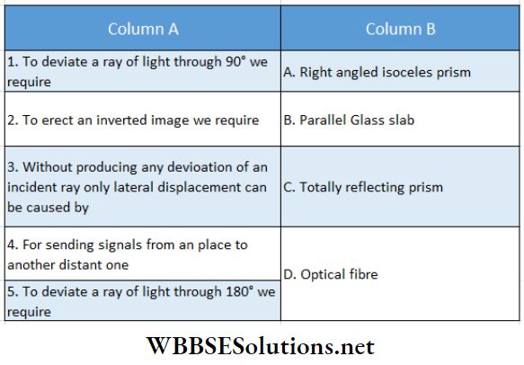
Answer:  1- A, C, 2-A, C, 3- B, 4- 4, 5- A, C

Question 2.

Class 12 Physics Unit 6 Optics Chapter 2 Refraction Of Light Deviative Angles.

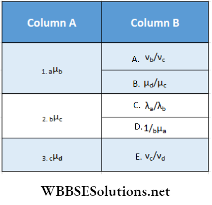
Answer: 1-C, D, 2- A, 3- B, E

Question 3.

Class 12 Physics Unit 6 Optics Chapter 2 Refraction Of Light Refractive Index Medium

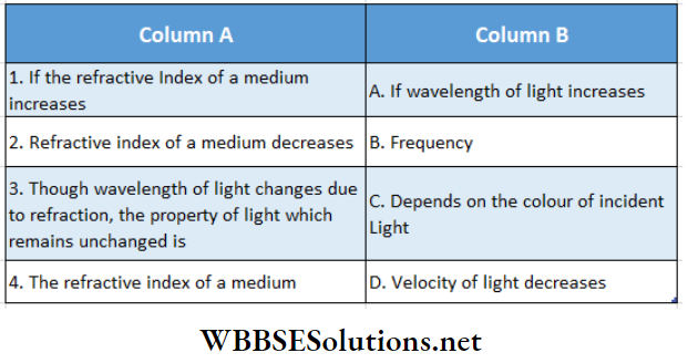
Answer: 1- D, 2- A, 3- B, 4. C

μ1, μ2 and μ3 are the refractive indices of the first, second and third medium respectively

Question 4.

Class 12 Physics Unit 6 Optics Chapter 2 Refraction Of Light Square Roots

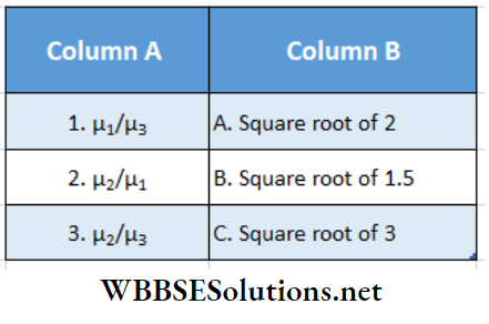
Answer: 1- B, 2-1, 3 -C

WBCHSE Class 12 Physics Notes For Refraction Of Light Prism

Optics Refraction Of Light Prism Of Some Definitions

Prism:

A prism is a portion of a transparent medium confined using two plane faces inclined to each other. In the DEFGHK is a prism and it is confined by the two planes DEHK and DFGK.

Class 12 Physics Unit 6 Optics Chapter 2 Refraction Of Light Prism

Refracting face:

The two plane faces inclined to each P S other at some angle by which the prism is bound are called the refracting faces. In, DEHK and DFGK are the refracting faces. BL

Edge:

The line along which the two refracting faces meet is called the edge of the prism. In Rg. 2.42, the line DK is the ‘ edge of the prism.

Refracting angle or angle of the prism:

The angle included between the two refracting faces is called the refract¬ ing angle or simply the angle of the prism. In the figure, ZEDF is the angle of the prism.

Side face and base:

In general, besides two refracting surfaces, a prism further on is enclosed by three more surfaces. Among these surfaces, two surfaces are triangular and are
placed perpendicular to the edge of the prism.

Read and Learn More Class 12 Physics Notes

In these two surfaces are DEF and KHG. These are the side faces of the prism. Another one is rectangular and situated perpendicular to the side face. In the surface is EFGH. It is called the base of the prism

Principal section:

The triangular cross-section cut by a perpendicular plane at right angles to the edge of a prism is called a principal section of the prism In ABC is a principal section of the prism

Light can enter or emerge from the prism through its refracting surfaces as those surfaces are plain and smooth In some cases, the base and side faces of a prism are made rough so that no light passes through it A prism is usually represented by its principal section

Refraction of Light along the Principal Section of a Prism

In ABC is the principal section of a prism. AB and AC are the refracting faces and BC is the base of the prism. A ray PQ is an incident on the face AB at Q where NQO is the normal. The prism is supposed to be an optically denser medium with

Class 12 Physics Unit 6 Optics Chapter 2 Refraction Of Light Principle Of The Prism

Respect to its surroundings. So, after refraction on plane AB, the refracted ray QR bends towards the normal NQO. The refracted ray QR is then incident on the face AC at H where N’RO is normal. The emergent ray RS bends av/ay from the normal N’RO after refraction.

So RQRS is the whole path of the ray of light. The angle between the direction of the incident ray and the direction of the’ emergent ray gives the angle of deviation. In, the angle of deviation, δ = ∠MTS.

Expression for the angle of deviation:

Let the angle of the prism = ∠BAC – A. For refraction on the face AB, the angle of incidence =∠PQN = i1, and the angle of refraction = ∠RQO = r1  for refraction on the face AC, the angle of incidence of QR = ∠QRO =r2, and the angle of refraction. = ∠N’RS =i2 .

Now we get from the ∠QRT, angle of deviation,

δ = ∠MTR = ∠TQR + ∠TRQ

= (i1 ~ r1) + (i2– r2) = i1 + i2– (r1+ r2) Now, from the quadrilateral AQOR, as NO and N’O are normals on AB and AC respectively, so A + ∠QOR = 180°.

Again, from the triangle QOR

∠QOR + r1 + r2 = 180°

∴ A = r1 + r2 and ……………………….(1)

δ  = i1 + i2-A ……………………….(2)

So the angle of deviation δ depends on the angle of incidence. From the principle of reversibility of light rays follows that, if a ray enters the face A C along SR at an angle of incidencei2 it will emerge along QP at an angle i1 and suffer the same deviation. In other words, the same deviation occurs for two values of i.

Angle of Minimum Deviation

‘The angle of deviation of a ray of light passing through a prism depends on the angle of incidence because in the relation

Class 12 Physics Unit 6 Optics Chapter 2 Refraction Of Light Angle Of Minimum Deviation

δ= i1 + i2– A, A is constant and i2 depends on i2 . A graph is drawn taking the angle of incidence z as abscissa and the angle of deviation o as ordinateThe graph indicates that the deviation decreases at first with the increase in the angle of incidence and then attains a minimum (δm) for a particular value of the angle of incidence i0. Then with a further increase in the angle of incidence, the; deviation also increases.

So for every prism, there is a fixed angle of incidence for which the deviation suffered by a ray of light traversing the prism minimal. This angle of deviation is called the angle of minimum deviation of a prism. The position of the prism for which the value of the deviation becomes minimum is called the position of minimum deviation of the prism. This position of the prism is unique i.e., for only, one position of the particular prism, the deviation becomes minimal.

Analysis of (i -δ) graph and condition of minimum deviation:

A line AB parallel to the i -i-axis is drawn. The coordinates of points, A and B are respectively (i1,  ) and (i2, δ ). The angle of deviation is o for an angle of incidence i1 or i2. We have seen that for angle of incidence i1 the emergent angle is z’2. The length of the line AB = (i2– i1). As the line AB moves parallel to itself downwards, the value of o decreases and the length of the line ( i2– i1) also decreases gradually. At point C, the length of the line AB becomes zero and o also becomes minimum. Then i2– i1 = 0 Or, i2= i1

So we can say that during refraction through a prism, when the angle of incidence and the angle of emergence are equal, the angle of deviation becomes minimal.

Condition of minimum deviation by calculus:

We know for refraction through a prism, the angle of deviation of a ray of light

Condition of minimum deviation by calculus: we know for refraction through a prism, the angle of deviation of a ray of light

δ = i1+i2-A ………………..(1)

And angle of the prism

A= r1 +r2 ………………..(2)

The angle of deviation 8 depends on the angle of incidence i1.

For minimum deviation δ

⇒ \(\frac{d}{d i_1}(\delta)=0\)

∴ \(\frac{d}{d i_1}\left(i_1+i_2-A\right)\) =0

Or, 1\(\frac{d i_2}{d i_1}\)

∴ \(\frac{d i_2}{d i_1}=-1\) ………………..(3)

Differentiating equation (2) we have,

⇒ \(\frac{d}{d r_1}(A)=\frac{d}{d r_1}\left(r_1+r_2\right)\)

⇒ \(0=1+\frac{d r_2}{d r_1} \quad \text { or, } \frac{d r_2}{d r_1}=-1\) ……………………(4)

For refraction at Q and R , according to Snell’s law we have, sin i1 = μ sin r1 and sin i2 = μ sin r2; where μ = refractive index of the. material of the prism.

Differentiating the above equations we have

⇒ \(\cos i_1 d i_1=\mu \cos r_1 d r_1 \quad \text { and } \cos i_2 d i_2=\mu \cos r_2 d r_2\)

∴  \(\frac{\cos i_1}{\cos i_2} \cdot \frac{d i_1}{d i_2}=\frac{\cos r_1}{\cos r_2} \cdot \frac{d r_1}{d r_2}\)  ………………………………(5)

From equations (3), (4) and (5) we have

⇒ \(\frac{\cos i_1}{\cos i_2}=\frac{\cos r_1}{\cos r_2^2} \quad \text { or, } \frac{\cos ^2 i_1}{\cos ^2 i_2}=\frac{\cos ^2 r_1}{\cos ^2 r_2}\)

Or, \(\frac{1-\sin ^2 i_1}{1-\sin ^2 i_2}=\frac{1-\sin ^2 r_1}{1-\sin ^2 r_2}\)

Or, \(\frac{1-\sin ^2 i_1}{1-\sin ^2 i_2}=\frac{\mu^2-\mu^2 \sin ^2 r_1}{\mu^2-\mu^2 \sin ^2 r_2}=\frac{\mu^2-\sin ^2 i_1}{\mu^2-\sin ^2 i_2}\)

Or, \(\frac{1-\sin ^2 i_1}{1-\sin ^2 i_2}=\frac{\left(\mu^2-\sin ^2 i_1\right)-\left(1-\sin ^2 i_1\right)}{\left(\mu^2-\sin ^2 i_2\right)-\left(1-\sin ^2 i_2\right)}\)

\(\frac{a}{b}=\frac{c}{d}=\frac{c-a}{d-b}\)

= \(\frac{\mu^2-1}{\mu^2-1}\)

= 1

∴ \(1-\sin ^2 i_1=1-\sin ^2 i_2 \quad \text { or, } \sin ^2 i_1=\sin ^2 i_2\)

Or, i1 =  i2

So the deviation is minimal when the angle of incidence (i1) is equal to the angle of emergence (i2)

WBCHSE Class 12 Physics Notes For Refraction Of Light Prism

The brightness of a ray of light at minimum deviation:

From the graph of the angle of incidence i and angle of deviation δ, it is found that generally if the angle of incidence is different, the angle of deviation is also different.

But if the angle of deviation attains its minimum value δm, then it is observed that for a wider range of angle of incidence (from i1 to  i2 vide, the angle of deviation of the ray becomes almost equal to the angle of minimum deviation δm, i.e., all the rays within this range emerge from the prism making a minimum angle of deviation δm.

Class 12 Physics Unit 6 Optics Chapter 2 Refraction Of Light Brightness Of A Ray Of Light At Minimum Deviation

So it can be said that in case of minimum deviation, the brightness of the emergent ray increases considerably. For this characteristic, the minimum deviation of a prism is of great importance

Path of Ray through a Prism for Minimum Deviation

Suppose a ray of light passes through a prism with minimum deviation along the path PQRS According to the condition of minimum deviation ix = i2. If the refractive index of the material of the prism is then

Class 12 Physics Unit 6 Optics Chapter 2 Refraction Of Light Path Of Ray A prism For Minimum Deviation

μ = \(\frac{\sin i_1}{\sin r_1}=\frac{\sin i_2}{\sin r_2}\)

r1 = r2

Since ∠AQR = 90°- r1 and ∠ARQ = 90°- r2 ,

So ∠AQR = ∠ARQ

Since, [r1 = r2]

So the triangle AQR is an isosceles triangle having AQ = AR.

So, for the minimum deviation of a ray, the point of incidence, Q and the point of emergence, R are equidistant from the vertex A of the prism.

So it is evident that when the deviation of a ray in a prism is minimum, the path of the ray through the prism becomes symmetrical.

Suppose, for the prism, AB = AC

∴ AQ= AR

∴ \(\frac{A Q}{A B}=\frac{A R}{A C}\)

i.e., the line QR is parallel to BC.

So, for an isosceles prism, when the deviation is minimum the path of the ray through the prism becomes parallel to the base of the prism.

Again the deviation of the ray due to refraction at AB = ( i1 – i2) and the deviation of the ray due to refraction at AC = ( i2 – i1). At the position of the minimum deviation of the prism,  i1= i2 and r1 = r2. So the deviations stated earlier become equal. Therefore, we can say that at the minimum deviation position of the prism, the total deviation is divided equally between the two refracting faces of the prism.

Refractive Index And Angle Of Minimum Deviation

We know that In the case of refraction of a prism, the angle of deviation of a ray δ = i1+ i2 = And the angle of the prism  A = r1 + r

For minimum deviation r1 = r2. , Again when i1 =  i2 then r1+ r2

So angle of minimum deviation

δm = i1+i2– A   = 2i1– A

Or, \(=\frac{A+\delta_{m}}{2}\)

Again, A = r1+r2 = 2r1

Now considering refraction at the face AB we have, angle of incidence = i1 and angle of refraction = r1

If the refractive index of the material of the prism is μ then

⇒ \(\frac{\sin i_1}{\sin r_1}=\frac{\sin \frac{A+\delta_m}{2}}{\sin \frac{A}{2}}\)

So, If we know the values of the angle of the prism μ, and the angle of minimum deviation δ , we can determine the value of the refractive Index of the material of the prism

Refraction Of Light Prism Of Some Definitions Numerical Examples

Example 1.  The refractive index of the material of a prism Is \(\sqrt{\frac{3}{2}}\) and the refracting angle Is 90°. of the angle of minimum deviation of the prism and the angle of Incidence at the minimum deviation position.
Solution:

Here A = 90°: Let the angle of the minimum deviation be m

We know, μ = \(\frac{\sin \frac{A+\delta_m}{2}}{\sin \frac{A}{2}}=\frac{\sin i_1}{\sin r_1}\)

⇒ \(\sqrt{\frac{3}{2}}=\frac{\sin \frac{90^{\circ}+\delta_m}{2}}{\sin \frac{90^{\circ}}{2}}=\frac{\sin \frac{90^{\circ}+\delta_m}{2}}{\sin 45^{\circ}}\)

Or, \(\sin \frac{90^{\circ}+\delta_m}{2}=\sqrt{\frac{3}{2}} \times \sin 45^{\circ}\)

= \(\frac{\sqrt{3}}{\sqrt{2}} \times \frac{1}{\sqrt{2}}=\frac{\sqrt{3}}{2}\)

⇒ \(i_1=\frac{90^{\circ}+\delta_m}{2}=60^{\circ}\)

Or, 90° + δm = 120°

δm = 120°- 90°

δm = 30°

⇒ \(r_1=\frac{A}{2}=\frac{90^{\circ}}{2}\)

= 45°

Example 2. The refractive of the material of a prism is \(\sqrt{2}\) and the angle of minimum deviation is 30. Calculate the value of the refracting angle of the prism.
solution:

Let the refracting angle of the prism be A We know, \(\)

⇒  \(\frac{\sin \frac{A+\delta_m}{2}}{\sin \frac{A}{2}}\)

Or, = \(\sqrt{2}=\frac{\sin \left(\frac{A+30^{\circ}}{2}\right)}{\sin \frac{A}{2}}\)

Or, \(\sqrt{2} \cdot \sin \frac{A}{2}=\sin \left(15^{\circ}+\frac{A}{2}\right)\)

= \(\sin 15^{\circ} \cdot \cos \frac{A}{2}+\cos 15^{\circ} \cdot \sin \frac{A}{2}\)

⇒ \(\frac{\sin \frac{A}{2}}{\cos \frac{A}{2}}=\frac{\sin 15^{\circ}}{\sqrt{2}-\cos 15^{\circ}}\)

Now, \(\sin 15^{\circ}=\sin \left(45^{\circ}-30^{\circ}\right)\)

= \(\frac{1}{\sqrt{2}} \cdot \frac{\sqrt{3}}{2}-\frac{1}{\sqrt{2}} \cdot \frac{1}{2}=\frac{\sqrt{3}-1}{2 \sqrt{2}}\)

Similarly , Cos 15°  \(\frac{\sqrt{3}+1}{2 \sqrt{2}}\)

∴ \(\tan \frac{A}{2}=\frac{\frac{\sqrt{3}-1}{2 \sqrt{2}}}{\sqrt{2}-\frac{\sqrt{3}+1}{2 \sqrt{2}}}\)

= \(\frac{\sqrt{3}-1}{3-\sqrt{3}}=\frac{1}{\sqrt{3}}\)

= tan 30°

\(\frac{\Lambda}{2}\) = 30°

Or, A= 60°

Example 3. The angle of minimum deviation is the same as the angle of a glass prism of refractive index = \(\sqrt{3}\). What is the angle of the prism
Solution:

According to the question,  δm = A

⇒ \(\frac{\sin \frac{A+\delta_m}{2}}{\sin \frac{A}{2}}\)

Or, \(=\frac{\sin \frac{A+A}{2}}{\sin \frac{A}{2}}=\frac{\sin A}{\sin \frac{A}{2}}\)

= \(\frac{2 \sin \frac{A}{2} \cos \frac{A}{2}}{\sin \frac{A}{2}}=2 \cos \frac{A}{2}\)

μ = \(\sqrt{3}\)

So, \(2 \cos \frac{A}{2}=\sqrt{3}\)

Or, \(\cos \frac{A}{2}=\frac{\sqrt{3}}{2}\) = cos 30°

Or, \(\frac{A}{2}=30^{\circ}\)

A = 30° × 2

A = 60°

Example 4. What- will be the angle of emergence of a ray of light -; n through a prism for an angle of incidence of 45°? The angle of the prism = 60°; refractive index of the prism = \(\sqrt{3}\)
Solution:

Here A = 60 ,μ =  \(\sqrt{3}\)

For refraction at the first face

μ = \(\frac{\sin i_1}{\sin r_1}\)

Or, \(\frac{\sin i_1}{\sin r_1}\)

Or, \(\sqrt{2}\)

Or, r1 =  30°

We know, that A = r1+r2

r2= A-r1 = 60°-30° = 30° = r1

So, the angle of emergence (i2) = angle of incidence (i1) = 45° The angle of emergence of the ray of light from the second face is 45°

Example 5. A ray of— light is incident at an angle- of- incidence- 40°—- on a prism having a refractive index of 1.6. What should be the value of the angle of the prism for minimum deviation? Given sin 40° = 0.6428; sin23°42; = 0.4018
Solution:

Here  μ = 1.6

The angle of incidence at the first face = i1 = 40

Let the angle of emergence at the second fac

For minimum deviation i1 = i2= 40

⇒ \(\delta_m=i_1+i_2-A=40^{\circ}+40^{\circ}-A\)

or, \(A+\delta_{m_1}=80^{\circ}\)

We know, \(\mu=\frac{\sin \frac{A+\delta_m}{2}}{\sin \frac{A}{2}} \text { or, } 1.6=\frac{\sin \frac{80^{\circ}}{2}}{\sin \frac{A}{2}}\)

or, \(\sin \frac{A}{2}=\frac{\sin 40^{\circ}}{1.6}=\frac{0.6428}{1.6}\)

= 0.4018= sin 23°42′

\(\frac{A}{2}\) = 23°42′

A = 23°42′ × 2

Or, A = 47° 24′

Example 6. The refracting angle of the n glass prism is 60° and tho refractive Index of glass is 1.6 The angle of incidence of a ray of light on the first refracting surface is 45°. Calculate the angle of deviation of the ray. Given that sin 26°14′ = 0.4419, sin 33°46′ = 0.5558 and sin 62°47′ = 0.8893 .
Solution:

Here A = 60°; ft – 1.6

The angle of incidence on the first face = i1 = 45

For refraction on the first face, ft = \(\frac{\sin i_1}{\sin r_1}\)

⇒ \(\sin r_1=\frac{\sin t_1}{\mu}=\frac{\sin 45^{\circ}}{1.6}\)

= \(\frac{1}{\sqrt{2} \times 1.6}\)

= 0.4419

= sin 26.23°

Or, r1 = 26.23°

We, know A = r1 +r2

r2 = A- r1 = 60°- 26.23° = 33.77°

For refraction at the second face

⇒ \(\frac{\sin i_2}{\sin r_2}\)

Or, sin =1.6 \(\frac{\sin i_2}{\sin 33.77^{\circ}}\)

Or, sin i2 = 1.6 × sin 33.77°

= 1.6 × 0.5559 = 0.8894

= sin 62.8°

i2 = 62.8°

So, the angle of deviation,

δ = i1 + i2-A = 45° + 62.8°- 60°

= 47.8°

Example 7.  If the refracting angle of a prism is A, the refractive index of its material is fi and the angle of deviation of a ray of light Incident normally on the first refracting face is 8, then prove that ft
Solution:

Angle of deviation for refraction in the prism,

δ = i1 + i -A and A = r1 + r2

For normal incidence ix = 0 and rx = 0

∴ δ  = i2-A Or, i2 = A + δ

A = r2

The refractive index of the prism,

μ = \(\frac{\sin i_2}{\sin r_2}=\frac{\sin (A+\delta)}{\sin A}\)

Example 8.  A ray of light Is an Incident at an angle of 60° a prism with a refracting angle 30°. If any emerges from the other face and makes an angle of 30° with the Incident ray then, show that the emergent ray passes perpendicularly through the refracting surface. Determine the refractive Index of the material of the prism.
Solution:

According to question’, δ = 30°, i1=6 0° and

A = 30°.

We know, δ = i1 + i2-A

∴ 30° = 60° + i1– 30° or, i2 = 0

The emergent ray Is perpendicular to the refracting surface.

Again, A = r2 + r1

As, i1 = 0 , so angle of incidence of the second face, r2 = 0

r1 = A = 30°

∴ The refractive index of the material of the prism

μ = \(\frac{\sin i_1}{\sin r_1}=\frac{\sin 60^{\circ}}{\sin 30^{\circ}}=\frac{\frac{\sqrt{3}}{2}}{\frac{1}{2}}\)

= \(\sqrt{3}\)

Example 9. A glass prism with a refracting angle of 60° and of refractive index 1.6, is immersed in water (refractive Index is 1.33). What is its angle of minimum deviation? [sin 36.87° = 0.6
Solution:

Here, A = 60°; aμb = 1.6; aμw =1.33

⇒ \({ }_w \mu_g=\frac{{ }_a \mu_g}{{ }_a \mu_w}=\frac{1.6}{1.33}\)

= 1.2

Let the angle of minimum deviation for the immersed prism is

⇒ \(w^{\mu_g}=\frac{\sin \left(\frac{A+\delta_m}{2}\right)}{\sin \frac{A}{2}}]\)

Or, \(1.2=\frac{\sin \left(\frac{60^{\circ}+\delta_m}{2}\right)}{\sin \frac{60^{\circ}}{2}}\)

Or, \(1.2 \times \sin 30^{\circ}=\sin \frac{60^{\circ}+\delta_m}{2}\)

Or, \(\sin \frac{60^{\circ}+\delta_m}{2}=1.2 \times \frac{1}{2}\)

= 0.6 = sin 36. 87

Or, \(\frac{60^{\circ}+\delta_m}{2}\) = 36.87

Or, \(\delta_m=73.74^{\circ}-60^{\circ}=13.74^{\circ}\)

Example 10. A ray of light passes through an equilateral prism In such a way triangle of incidence becomes equal to the angle of emergence and each of these angles is \(\frac{3}{4}\) of the angle of deviation. Determine the angle of deviation.
Solution:

Here, A= 60 and i1= i2= \(\frac{3}{4} \delta\)

Now \(\)

= \(\frac{3}{2} \delta-60^{\circ}\)

Or, \(\frac{1}{2} \delta=60^{\circ}\)

Or = 120

∴ Angle od deviation = 120

Example. 11  The angle of minimum deviation of a glass prism of refracting angle 60° is 30°. If the velocity of light In a vacuum is 3 × 10⁻⁸m s-1, then determine Its velocity In the glass
Solution:

The refractive index of the material of the prism,

μ =\(\frac{\sin \frac{A+\delta_m}{2}}{\sin \frac{A}{2}}\)

μ = \(\frac{\sin \frac{60^{\circ}+30^{\circ}}{2}}{\sin \frac{60^{\circ}}{2}}=\frac{\sin 45^{\circ}}{\sin 30^{\circ}}\)

= \(\frac{\frac{1}{\sqrt{2}}}{\frac{1}{2}}=\sqrt{2}\)

Again , \(\mu=\frac{\text { velocity of light in vacuum }}{\text { velocity of light in glass }\left(\nu_g\right)}\)

⇒ \(\sqrt{2}=\frac{3 \times 10^8}{v_g}\)

⇒  \(v_g=\frac{3 \times 10^8}{\sqrt{2}}=2.12 \times 10^8 \mathrm{~m} \cdot \mathrm{s}^{-1}\)

WBCHSE Class 12 Physics Notes For Types of Reflecting Prisms

Optics

Refraction Of Light Types of Reflecting Prisms

Total Reflecting Prism:

Total internal reflection of light can easily take place in a prism made of crown glass and whose principle cross-section is a right-angled isosceles triangle. So this type of prism is called a total reflecting prism.

ABC is die principal section of a total reflecting prism { Its sides.AS and BC are equal and ∠ABC = 90′. If the ray PQ is incident perpendicularly on the face AS, it is incident on the face AC at an angle of 45° which is greater than the critical angle of glass and air, about 42°. So it is totally
reflected and passes along RST perpendicular to the side SC. Thus the hypotenuse face

AC of the prison acts as a plane mirror. So it is called a total reflecting prism. it is to be noted that in this case, the deviation of the ray is 90°

Class 12 Physics Unit 6 Optics Chapter 2 Refraction Of Light Reflecting Prism

Advantages of a total reflecting prism:

  1. In the case of a plane mirror multiple images may be formed due to several reflections from the front and the back surfaces of the mirror and the images thus formed is also bright.
  2. But in the case of a total reflecting prism, only one bright image is formed due to total internal reflection.
  3.  When the mercury coating of the back surface of a plane mirror is damaged, the image becomes indistinct.
  4. But such a problem arises in a totally reflecting prism mirror is damaged, and the image becomes indistinct. But such a problem arises in a totally reflecting prism

Disadvantages of a total reflecting prism:

  1. A total-reflecting prism is more costly than a plane mirror.
  2. If the glass of the prism is not completely homogeneous, the image becomes less distinct

Effecting prism: The inverted image of an object can be made erect with the help of a total reflecting prism.

Erecting of the image by deviating a ray through 0°:

ABC is an isosceles right-angled prism, where ∠A = 90° uniting side of prism for no emergent ray j and ∠B = ∠C = 45°. Suppose that QP is the inverted image of an object. The ray coming from Q after refraction on the face AB is incident on the face BC at an angle greater than the critical angle of glass and air. So the ray is totally reflected from this face and emerging from the face AC forms its image at Q1.

Similarly, a ray starting from P comes to the point P1. So this P1Q1 is inverted with respect to QP, thus erecting an inverted object. can type of prism is called a total reflecting prism.

Class 12 Physics Unit 6 Optics Chapter 2 Refraction Of Light Isosceles Right Angled Prism

In this case, no deviation of the ray has taken place.

In instruments like telescopes, binoculars, etc., total reflecting

RST is perpendicular to the side SC. Thus the hypotenuse face, prism is therefore used to erect an inverted image.

Erecting of the image by deviating 180°:

To get an erect Image, the above-mentioned prism can be used in another way. QP is the Inverted Image of an object. The hypotenuse faces BC of the prism ABC Is held In front of it. A ray of PX from P is incident normally on the face BC and enters the prism.

After refraction, it Is incident at Y on the face AB. ‘I lie angle of incidence of the ray AT at the face AH is 45° which Is greater than the critical angle (nearly 42) of glass and air. So the ray moves along YZ after total reflection at Y and is incident on the face AC.

For The same reason, the ray moves along ZR after total reflection at Z and incident normally on the face BC. It emergences RP’ and comes to the point P’

Class 12 Physics Unit 6 Optics Chapter 2 Refraction Of Light Inverted Image And The Hypotenuse Face

Similarly, a ray coming from Q comes to the point  Q’ obviously according to the figure, the image P’Q’ becomes inverted relative to PQ. So the erect image P’Q’ of an inverted object Is thus formed.

Each incident ray bends twice at 90°, thus producing a total deviation of 180°. So, an inverted image can be made erect by deviating a ray through 180°.

Prism periscope:

Total reflecting prisms are commonly used nowadays in good-quality periscopes instead of inclined parallel mirrors. This type of periscope is called prism periscope and the image formed by a prism periscope is more bright than that formed by a simple periscope.

The periscope tube contains two right-angled isosceles prisms P1 and P2. P1 is fixed at the top in such a way that rays of light coming from a.Distant object enter the prism through a window and after total internal reflec¬ tion goes downwards. The hypotenuse face P2, which is fixed at the bottom receives these rays and reflects them totally In n horizontal direction through the ohworvinlon window. Thu observer thus sees an exact Image of the distant object.

Class 12 Physics Unit 6 Optics Chapter 2 Refraction Of Light Prism Periscope

Unit 6 Optics Chapter 2 Refraction Of Light Types of Reflecting Prisms Numerical Examples

Example 1. A man with a telescope can just observe point A on the circumference of the base of an empty cylindrical vessel.   When the vessel is filled completely with a liquid of refractive index 1.5 the man can just observe the middle point B of the base of the vessel without moving either the vessel or the telescope If The diameter of the base of the vessel is 10 cm, what is the height of the vessel.
Solution:

When the vessel Is empty, a light from point A enters the telescope ‘l’ following the straight path AO. When the vessel Is filled with the liquid, a ray of light from point II moves along BO and after refraction in air enters the telescope. Let h be the height of the vessel.

Class 12 Physics Unit 6 Optics Chapter 2 Refraction Of Light Empty Vessel

Here

According to the figure

⇒ \(\frac{\sin l}{\sin r}=\frac{1}{\mu} \quad \text { or, } \mu=\frac{\sin r}{\sin t}\)

Or, \(1.5=\frac{\frac{A C}{A O}}{\frac{B C}{B O}}=\frac{A C}{A O} \times \frac{B O}{B C}=\frac{A C}{B C} \times \frac{B O}{A O}\)

Or,\(1.5=\frac{10}{5} \times \frac{\sqrt{B C^2+C O^2}}{\sqrt{A C^2+C O^2}}=2 \times \frac{\sqrt{25+h^2}}{\sqrt{100+h^2}}\)

Or,\(2.25=\frac{4\left(25+h^2\right)}{100+h^2}\)

h = 8.45 cm

Example 2. A post remains above is dipped the water straight of the in a pond.“The rays of the sun are Inclined at an angle of 45° to the surface of water what will be the length of the shadow of the post at the bottom of the pond? The refractive index of water p
Solution:

ABC is the post and BFG is the surface of water

The length of the shadow at the bottom of the pond = CD

Class 12 Physics Unit 6 Optics Chapter 2 Refraction Of Light Pond

Let CE = BF= x = ED = yellow

According to the figure

∠AFN = i= angle of incidence

∠BAF = i

∠EFD = r = angle of refraction

We know, \(\mu=\frac{\sin i}{\sin r}\)

⇒ \(\frac{4}{3}=\frac{\sin 45^{\circ}}{\sin r}\)

Since i = 45°

Or, \(\frac{3}{4} \times \frac{1}{\sqrt{2}}=\frac{3}{4 \sqrt{2}}\)

From the

tan i= \(\frac{x}{1}\)

Or, \(\tan 45=\frac{x}{1}\)

Or, x = 1cm

tan 45° = \(\frac{x}{1}\)

Again, \(\sin r=\frac{y}{\sqrt{y^2+9}} \quad \text { or, } \frac{3}{4 \sqrt{2}}=\frac{y}{\sqrt{y^2+9}}\)

Or, y²× 32 = 9(y² + 9) or, 23y² = 81

Or, \(\frac{81}{23}\)

y²= 1.879 m

The length of the shadow of the post at the bottom of the pond = x+y= 1+1.876

= 2.876 m

Example 3. There is a point object at a height above the surface of water in a tank. If the bottom of the tank acts as a plane mirror where will be the Imago formed? If on observer looks from the air at the surface of the water normally, calculate the distance of the image front the surface of the water of the tank formed by the mirror-like bottom surface of the tank. Refractive Index of water = \(\frac{4}{3}\)
Solution:

Q is a point source. For refraction in water, the apparent position of Q is Q’

Class 12 Physics Unit 6 Optics Chapter 2 Refraction Of Light Refractive Index In Water

So, \(\mu=\frac{\text { apparent height }}{\text { real height }}=\frac{P Q^{\prime}}{P Q}\)

= \(\frac{P Q^{\prime}}{h}\)

Or, PQ’ = μh =  \(\frac{4}{3}\)

Therefore the distance of Q’ from the bottom of the tank

= d +\(\frac{4}{3}\)

So the image of Q’ will be formed at a distance of (d +\(\frac{4}{3}\)) from the bottom of the tank

= d + d +\(\frac{4}{3}\)h = 2d +\(\frac{4}{3}\)h

⇒ \(\frac{4}{3}\) = \(\frac{2 d+\frac{4}{3} h}{x}\)

=  \(x\frac{3}{4}\left(2 d+\frac{4}{3} h\right)=\frac{3}{2} d+h\)

Example 4.  A rectangular glass slab of thickness 3 cm and of refractive Index 1.5 is placed in front of a concave mirror, perpendicular to Its principal axis. The radius of curvature of the mirror Is 10 cm. Where Is an object to be placed on the principal axis so that Its image will he formed on the object?
Solution:

The rectangular glass slab is placed perpendicular to the principal axis of the concave mirror M1M2 Suppose that if an object is placed at O on the principal axis, its image will be formed at
O. OABM1 is the path of the ray. Tiie ray after reflection at M1 retraces the path and forms an image at O. So the ray BM1 must be incident on the mirror at M1  perpendicularly. If Af, B must be incident on the mirror at Af, perpendicularly. If Af, B O’ is the centre of curvature of the concave mirror.

PO’ = 10 cm

Now OO’ = \(t\left(1-\frac{1}{\mu}\right)=3\left(1-\frac{1}{1.5}\right)\)

= 3-2 = 1cm

So, the distance of O from the concave mirror

= PO’ + OO’ = 10 + 1 = 11 cm

Class 12 Physics Unit 6 Optics Chapter 2 Refraction Of Light Rectangular Glass Slab

Example 5. A cross mark at the bottom of an empty vessel is focused with the help of a vertical microscope. Now! water (refractive Index = \(\frac{4}{3}\) ) Is poured into the vessel.  The height of water in the vessel Is 4 cm. Another lighter liquid which does not mix with water and has  a refractive index is, is poured into the water. The height of the liquid is 2 cm. How much should the microscope be raised vertically to focus the mark again?
Solution:

The real depth of the combination of water and the

liquid = 4 + 2 = 6 cm

The apparent depth of the cross-mark

⇒ \(\frac{4}{\frac{4}{3}}+\frac{2}{\frac{3}{2}}=3+\frac{4}{3}\)

= 4.33 cm

So, to focus the cross mark, the microscope is to be raised vertically through a height (6-4.33) = 1.67 cm.

WBCHSE Class 12 Physics Notes For Types Of Reflecting Prisms

Example 6. A concave mirror with a radius of curvature of 1 m Is placed at the bottom In a reservoir of water. When the sun Is situated directly over the head, the mirror forms an Image of the sun. If the depth of water Is  80 cm and  40 cm, calculate the Image distances from the mirror, f Given \(\mu_w=\frac{4}{3}\)

Solution:

The sun is an object situated at infinity. So its image will be formed by the concave mirror at its focus i.e. \(\frac{100}{2}\) = 50 cm above the mirror.

When the depth of water in the reservoir is 80 cm the image is formed at n distance of 50 cm inside water from the mirror. : § But when the depth of water is 40 cm the image will be formed in air. Light rays will be refracted while passing from water t0 ain So> the refracted rays wiU converge at O’ and an image will be formed at O’

Displacement of the image

= \(O O^{\prime}=t\left(1-\frac{1}{\mu}\right)=10\left(1-\frac{3}{4}\right)\)

= \(10 \times \frac{1}{4}\)

= 2.5 cm

Distance of image from the mirror

= PO’ = 50 – 2.5

= 47.5 cm

Class 12 Physics Unit 6 Optics Chapter 2 Refraction Of Light Refracted Rays

Example 7. The width of a rectangular glass slab is 5 cm. From a point on Its bottom surface, light rays are incident on its top face and after total reflection form a circle of light of radius 8 cm. What is the refractive Index of the
Solution:

Let o be a bright point at the bottom face of the rectangular slab. light rays starting from

Return to the bottom face after total reflection from the upper face of the slab.

As a result, a circle of light of radius OA = OB = 8 cm formed on the bottom face. So the angle of incidence on the upper face is P(. (critical angle) glass slab

According to the

OP = \(\sqrt{O C^2+P C^2}=\sqrt{(4)^2+(5)^2}\)

= \(\sqrt{41} \mathrm{~cm}\)

Refractive index \(\)

\(\mu=\frac{1}{\sin \theta_c}=\frac{1}{\frac{O C}{O P}}\) \(=\frac{O P}{O C}=\frac{\sqrt{41}}{4}\)

= 1.6

Class 12 Physics Unit 6 Optics Chapter 2 Refraction Of Light Bottom Space Of Rectangular Slab

Example 8.  A glass sphere having a centre at 0 and two perpendicular diameters AOB and COD. A ray parallel to AOB is incident on the sphere at P where AP = PC and emerges from the sphere at B. Calculate the refractive index of glass and the deviation of the emergent ray
Solution:

Class 12 Physics Unit 6 Optics Chapter 2 Refraction Of Light Deviation Of The Emergent Ray

According to the  arc AP = arc PC

∠AOP = ∠POC = 45° = i,

∠POB = 45° + 90° = 135°

From the triangle POB,

r+r+ 135° = 180° or, 2r = 45° or, r = 22.5°

= \(\frac{\sin i}{\sin r}=\frac{\sin 45^{\circ}}{\sin 22.5^{\circ}}\)

= 2 cos 22.5° = 2 × 0. 924 = 1.85

Angle of deviation

δ  =i-r+i-r = 2 (i-r) = 2(45°-22.5°)

= 2 × 22.5° = 45°

Example 9. A glass slab is placed on a page of a book kept horizontally. What should be the value of the minimum refractive index of the glass slab so that the printed letters of the page will not be visible from any vertical side of the slab? 
Solution:

It is assumed that there is a thin layer of air between the page of the book and the glass slab. So any ray coming from

any portion of the page of the hook Is Incident on the glass slab According to the figure, at an angle of almost

Class 12 Physics Unit 6 Optics Chapter 2 Refraction Of Light A Glass Slab

If the angle of refraction Is Φ and the refractive index of glass Is μ, S. then, sin Φ = \(\frac{1}{\mu}\)

If θC is the critical angle, then sin θC = \(\frac{1}{\mu}\)

This refracted ray is incident on any vertical l side of the slab at an angle θ  (say) So. θ + Φ = 90°.

If  . θ is greater than Φ, a total internal reflection of light takes place and the printed letters of the page will not be visible from any vertical side, μ will be minimum when. θ = Φ

2Φ = 90° , Or, Φ = 45°

∴ \(\mu_{\min }=\frac{1}{\sin \phi}=\frac{1}{\sin 45^{\circ}}\)

= \(\sqrt{2}\)

= 1.414

Example 10. A surface of a prism having a refractive index 1.5 is covered with n liquid of refractive index \(\frac{3 \sqrt{2}}{4}\) . What should be the minimum angle of incidence of an incident ray so that on the other surface of the prism tire ray will be totally reflected from the surface covered with liquid? The refracting angle of tho prism =75° [sin48°36′ = 0.75].
Solution:

Let the critical angle between the prism and the liquid be θC. If the ray of light is totally reflected from the surface covered with liquid then the angle of incidence of the ray on the surface is θC

Class 12 Physics Unit 6 Optics Chapter 2 Refraction Of Light Refracting Angle Of The Prism

So, 1.5 sin θC = \(\frac{3 \sqrt{2}}{4}\)

Or, \(\frac{3 \sqrt{2}}{4}\)

Or, \(\frac{3 \sqrt{2}}{4}\) x \(\frac{10}{15}\)

= \(\frac{1}{\sqrt{2}}\)

Again , r1+ θC = A

Or,  r1+ 45° = 75°  Or, = 30°

Now , sin i1 = μ sin r1 = 1.5 sin 30° = 0.75 Or, i1= 48° 36′

Example 11. A ray of light Is Incident normally on one, side of on isosceles right-angled prism and Is totally reflected on the other side.

  1. What Is the value of minimum refractive lodes of the material of the prism?
  2. If the prism Is Immersed In water, draw the diagram showing the direction of the emergent ray. In the diagram, point out the values of the angles,μ of water \(\frac{4}{3}\)

Solution:

1. ABC Is an Isosceles light-angled prism and Its sides are AB= BC The light lay PQ Is incident on the face AR normally and enters the prism. The ray Is an Incident at R on the face AC.

It Is evident from the figure that angle of Incidence of the ray at R Is 45° . Now if the ray Is to be totally reflected from R then this angle of incidence should he greater than the critical angle of the material of the prism μ maximum critical angle will be θC = 45° . If H be the minimum refractive Index of the material of the prism then,

sinθC  = \(\frac{1}{\mu}\)

Or, in 45° = \(\frac{1}{\mu}\)

Or, = \(\frac{1}{\mu}\)

= 1.414

Class 12 Physics Unit 6 Optics Chapter 2 Refraction Of Light Right Angled Prism And Totally Reflected From The Other Side

2. If the prism is immersed in water, then the refractive Index of glass relative to water is,

⇒ \({ }_u^{\mu_E}=\frac{\mu_S}{\mu_i}=\frac{\sqrt{2}}{\frac{4}{3}}=\frac{3 \sqrt{2}}{4}\)

If the critical angle between the prism and water is  θC

⇒ \(\theta_c^{\prime}=\sin ^{-1} \frac{1}{w^{\mu_g}}=\sin ^{-1}\left(\frac{4}{3 \sqrt{2}}\right)\)

= 70.53°

But the angle of Incidence at R is 45° [Fig. 2.64(b)] and it Is less than the critical angle. So at R, light rays will not be totally reflected. It will be refracted and will enter water. If the angle of refraction is r, then

⇒ \(\sqrt{2} \sin 45^{\circ}=\frac{4}{3} \sin r\)

sin r= \(\sqrt{2} \times \frac{3}{4} \times \frac{1}{\sqrt{2}}\)

= 0.75 = sin 48.59°

Or, r = 48.59°

Example 12.  A ray of light Is incident grazing the refracting surface of a prism having refracting angle A. It emerges the other refracting surface making an angle θ with the normal to the surface. Prove that the refractive index  of the material of the prism is given by \(\mu=\left[1+\left(\frac{\cos A+\sin \theta}{\sin A}\right)^2\right]^{1 / 2}\)
Solution:

For grazing incidence on the refracting surface AB of the prism, i1 = 90°

Class 12 Physics Unit 6 Optics Chapter 2 Refraction Of Light Grazing The Refacting Surface Of Prism

So, in this case r1 = dc (critical angle)

Now, A = r1 + r2 or, r2= A-r1 = A – θC

Considering refraction at the second refracting surface, AC

We get \(\mu=\frac{\sin \theta}{\sin r_2}\)

Or, \(\sin \theta=\mu \sin r_2=\mu \sin \left(A-\theta_c\right)\)

⇒ \(\mu\left[\sin A \cos \theta_c-\cos A \sin \theta_c\right]\)

But \(\sin \theta_c=\frac{1}{\mu} \text { and } \cos \theta_c=\sqrt{1-\frac{1}{\mu^2}}=\frac{\sqrt{\mu^2-1}}{\mu}\)

⇒ \(\sin \theta=\mu\left[\sin A \frac{\sqrt{\mu^2-1}}{\mu}-\cos A, \frac{1}{\mu}\right]\)

⇒ \(\sin A \sqrt{\beta^2-1}-\cos A\)

Or, \(\sin \theta+\cos A=\sin A \sqrt{\mu^2-1}\)

Or, \(\frac{\sin \theta+\cos A}{\sin A}=\sqrt{\mu^2-1}\)

Or,\(\mu^2-1=\left(\frac{\sin \theta+\cos A}{\sin A}\right)^2\)

Or,\(\mu^2=1+\left(\frac{\sin \theta+\cos A}{\sin A}\right)^2\)

Or,\(\mu=\left[1+\left(\frac{\sin \theta+\cos A}{\sin A}\right)^2\right]^{\frac{1}{2}}\)

Example 13. A ray of light incident normally on a refracting surface of the prism it totally reflated from the other refracting surface. If the prism it Immersed In water how will the ray act? The refractive index of a glass of =1.5; the refractive index of water = 1.33.
Solution:

At the ray of light it incident on the face of the prism normally so it goes straight through the surface. The ray it incident j on the second refracting face and is totally reflected. So the angle i or, of Incidence of the ray at the second face is greater than the critical  angle θC

⇒ \(\sin \theta_C=\frac{1}{a^{\mu_E}}=\frac{1}{1.5}=0.667\)

= sin 41.8°

θC = 41.8°

Now, if the prism is immersed in water, the refractive index of glass j with respect to water is,

wμg =aμg /aμw

= \(\frac{1.5}{1.33}\)

= 1.128

In this case, if the critical angle is  θ’C then

⇒ \(\sin \theta_C^{\prime}=\frac{1}{u^{\mu_g}}\)

= \(\frac{1}{1.128}\)

θ’= sin 62.44°

So the angle of incidence of the ray at the second face (41.8) is less than the critical angle (62.44). Hence, instead of being . totally reflected from the second face, the ray is refracted through it.

Example 14. A tank height of 33.25 cm is completely filled with liquid (μ= 1.33).An object is placed at the bottom of the tank on the axis of a concave mirror.   Image of the object is formed 25 cm below the surface of the liquid . What is the focal length of the mirror?

Class 12 Physics Unit 6 Optics Chapter 2 Refraction Of Light Height Of The Tank On The Axis Of Concave Mirror
Solution:

Here, R is the actual position of the object and A is the apparent position of the image

We, know, \(\mu=\frac{\text { real depth }}{\text { apparent depth }}\)

Or, 1.33  \(=\frac{33.25}{x_a}\)

Therefore, the apparent depth of the object

Here, object distance , u = \(-\left(15+\frac{33.25}{1.33}\right)\)

And image distance, v= -(15+25)cm = -40 cm

Applying the mirror equation, we get

⇒ \(-\frac{1}{40}-\frac{1}{40}=\frac{1}{f}\)

Or, f = \(-\left(\frac{40 \times 40}{40+40}\right)\) = -20

Therefore, the required focal length is 20 cm.

Example 15. What should be the minimum value of the refractive index of a right-angled isosceles prism to that the is F prism can deviate a ray through 180′ by total internal reflection

Class 12 Physics Unit 6 Optics Chapter 2 Refraction Of Light Rigt Angled Isosceles Prism

Solution:  ABC is a right-angled isosceles triangle, whose ∠ABC is 90 and AB = BC

Here light ray is incident along MN on the side AB and is reflected back along NO. Now, the reflected ray NO is incident on side BC and gets reflected along the path OP.

Therefore, light rays suffer total internal reflection when incident ic onsides AB and BC

It is clearly seen that the value of incident angle ig on sides AB and BC is 45° or less than 45°

ic ≤ 45°

sin-1 1/μ <45°

Or, 1/μ < sin 45°

Or,μ > \(\sqrt{2}\)

Therefore, the refractive index of the material of the prism is at least Jz so that the prism can deviate a ray through 180° by total internal reflection

Example 16. The face of the prism of refracting angle A is coated with silver. A light ray after first being Incident at an angle of Incidence 2A on the first face of the prism, is refracted and is then reflected from the second face, retracing its path. Calculate the value of the refractive index of the prism
Solution:

Let PQR be a glass prism. The refracting surface PR of the prism is coated with mercury

Class 12 Physics Unit 6 Optics Chapter 2 Refraction Of Light Prism Is Coated With Mercury

In the, incident ray DB is refracted along BC and the light ray returns following the same path after getting reflected from the surface PR

∴ ∠PCB = 90°

And ∠PBC = a = (90°-A) ………………………………… (1)

Where BPC= refracting angle of the prism = A-\theta_c\right

Again, from the a+r = 90°

∴ a =  (90°-r) ……………………………….(2)

Comparing equations (1)and (2), we may write

Where , \(=\frac{\sin i}{\sin r}=\frac{\sin 2 A}{\sin A}\)

Or, \(\mu=\frac{2 \sin A \cos A}{\sin A}\)

μ = 2cos A

Therefore, the required refractive index is 2 cosA.

Example 17. A ray of light falls normally on one side other than the hypotenuse of a right-angled isosceles prism of refractive index 1.5. From which side will the ray emerge from the prism? Find the deviation of the incident ray
Solution:

ABC is a right-angled isosceles triangle i.e., Angle of prism A = 90

Class 12 Physics Unit 6 Optics Chapter 2 Refraction Of Light Right Angled Isosceles Triangle

∠ABC = ∠ACB = 45°

AB. The ray of light is incident normally on the side AC and is inci¬ dent on the side BC at an angle 45°

.As a result, after total internal reflection, the ray passes along QR perpendicular to the side

Now, the angle of deviation = ∠SQR = δ = 90°

Example 18. A vessel contains a liquid of refractive index \(\frac{5}{3}\). Inside j the liquid, S is a point source which is observed from above the liquid. An opaque disc ot radius 1 cn, is floating on the liquid such that its centre is just the source, at this circumstance liquid of the vessel is leaving gradually through a hole. What is the depth of the liquid, so that the source no more remains visible from above
Solution:

Let x be the required dÿepth obviously, at this position light rays from the source S must be incident at a critical angle (dc) at the edge of the disc

Class 12 Physics Unit 6 Optics Chapter 2 Refraction Of Light Critical Angle At Edge Of The Disc

So, \(\sin \theta_c=\frac{1}{\sqrt{1+x^2}}\)

Also \(\sin \theta_c=\frac{1}{\mu}=\frac{3}{5}\)

\(\frac{3}{5}=\frac{1}{\cos \sqrt{1+x^2}}\)

Or, \(\)

Or, \(1+x^2=\frac{25}{9}\)

= \(x=\frac{4}{3}\)

= 1.33 cm

WBCHSE Class 12 Physics Refraction Of Light Short Questions And Answers

Optics

Refraction Of Light Short Questions And Answers

Question 1. A prism is made of glass of unknown refractive index A parallel beam of light incident on the face of the prism. By rotating the prism, the angle of minimum deviation la j measured to be 40° What is the refractive Index of the material of the prism? If the prism is placed In water j (refractive index  1.33 ). predict the new angle of minimum j deviation of a parallel! a beam of light Refracting angle of the prism is 60°
Answer: 

The refractive index of the material of the prism

μ = \(\frac{\sin \frac{A+8}{2}}{\sin \frac{A}{2}}=\frac{\sin \frac{60^{\circ}+40^{\circ}}{2}}{\sin \frac{60^{\circ}}{2}}\)

= \(\frac{\sin 50^{\circ}}{\sin 30^{\circ}}\)

= 1.53

When placed in water,

w μg= aμg /aμw

= \(\frac{1.53}{1.33}\)

w μg= \({ }\frac{\sin \frac{A+\delta_m^{\prime}}{2}}{\sin \frac{A}{2}}\)

Or, 1.15\(\sin \frac{60^{\circ}}{2}=\sin \frac{60^{\circ}+\delta_m^{\prime}}{2}\)

∴ δ’m= 10.2°

= 10. 12′

Question 2. A small pin fixed on the table and top of it is viewed from above from a distance of 50 cm. By what distance would the tire pin appear to be raised if it is viewed from the same point through a 15 cm thick glass slab held parallel to the table?

The refractive index of glass = 1.5. Does the answer depend on the location of the slab? The apparent displacement of the pin

x = d\(\left(1-\frac{1}{\mu}\right)\)

[ d= apparent depth and = refractive index]

= 15 (1-\(\left(1-\frac{1}{1.5}\right)\) = 5 cm

Fors mall angles of Incidence the answer will not depend on the position of the glass

Class 12 Physics Unit 6 Optics Chapter 2 Refraction Of Light Internal Reflection Inside The Pipe Take Place

Question 3. A cross glass fiber with a refractive Index of 1.68. The outer covering of the pipe is made of material with a refractive index of 1.44. What Is the tango of the angles of Incident rays with the axis of the pipe for which the total internal reflection inside the pipe takes place as shown In the figure? What is the answer If there is no outer covering of the pipe?  If there is no covering, then

If there is no covering, then

⇒ \(i^{\prime}=\sin ^{-1}\left(\frac{1}{1.68}\right) \approx 36.5^{\circ}\)

We know, \(\frac{\sin t}{\sin r}=\mu\)

∴  sin i =  sin 53.5° × 1.65 a 80.3 × 1.65 = 1.33 which is absurd as sin imax  = sin 90° = 1

A mass must be less than 53.5° which means

0°<K90° Thus total internal reflection will take a plate for any angle of incidence ranging from 90°

Question 4. A diver underwater looks obliquely at a fisherman standing on the bank of a lake. Would the fisherman look taller or shorter than he Is?
Answer:

The displacement of the Image of the head of the fisherman The displacement of the Image of the head of the fisherman

Question 5. At what angle should a ray of light be Incident on the face of a prism of refractive angle 60° so that it Just suffers total internal reflection at the other face? The refractive index of the material of the prism Is 1.524. 
Answer:

The limiting value of the angle of incidence,

i = \(\sin ^{-1}\left[\sin A \sqrt{\mu^2-1}-\cos A\right]\)

= \(\sin ^{-1}\left[\sin 60^{\circ}\left(\sqrt{1.524^2-1}\right)-\cos 60^{\circ}\right]\)

= 29.73 30

WBCHSE Class 12 Physics Refraction Of Light Short Questions And Answers

Question 6. Calculate the speed of light in a medium whose critical angle is 45s. Mention two practical applications of optical fiber. 

It is the critical angle of any medium concerning vacuum or air and // is the refractive index of the medium

⇒ \(\sin \theta_c=\frac{1}{\mu}\)

According to the question

⇒ \(\frac{1}{\sin \theta_c}=\frac{1}{\sin 45^{\circ}}=\frac{1}{\frac{1}{\sqrt{2}}}=\sqrt{2}\)

The velocity of light in air or vacuum,

c = 3 x 10⁸ m/s

Velocity of light in the medium

ν = \(\frac{c}{\mu}=\frac{3 \times 10^8}{\sqrt{2}}\) ‘

= 2.12

Question 7. The refracting angle of a prism is 60° and the refractive index of its material is \(\sqrt{\frac{7}{3}}\) Find the minimum angle of incidence of a ray of light falling on one refracting face of the prism such that the emerging ray will graze the other refracting face
Answer:

⇒ \(i_1=\sin ^{-1}\left[\sin A \sqrt{\mu^2-1}-\cos A\right]\)

Here, \(\mu=\sqrt{\frac{7}{3}}\)

Or, \(\mu^2-1=\frac{4}{3}\)

⇒ \(\sqrt{\mu^2-1}=\sqrt{\frac{4}{3}}=\frac{2}{\sqrt{3}}\)

Given that A = 60

Sin A = \(\frac{\sqrt{3}}{2}\)

Cos A = \(\frac{1}{2}\)

Hence, \(\sin ^{-1} \frac{\sqrt{3}}{2} \times \frac{2}{\sqrt{3}}-\frac{1}{2}\)

= \(\sin ^{-1} \frac{1}{2}\)

= 30°

Question 8. For the same value of angle of incidence, the angle of refraction in three media A, B, and C are 15°, 25’, and 35° respectively. In which medium would the velocity of light be minimum?

Refractive index μ = \(\frac{\sin i}{\sin r}\)

For the same value of i, μ ∝ \(\frac{1}{\sin r}\)

In the given problem

r1<r2<r3 Or, sin r1<sinr2< sinr3

As velocity oflight, v = \(\frac{c}{\mu}\) i.e \(\nu \propto \frac{1}{\mu}\) , we have ν123

So In the Grst medium, the die velocity of light Is minimal.

Question 9.  Two monochromatic rays of light are incident normally on the face AB of an isosceles right-angled prism ABC. The refractive indices of the glass prism for the two rays 1 and 2 are respectively13 and13. Trace the path of these rays after entering through the prism

Class 12 Physics Unit 6 Optics Chapter 2 Refraction Of Light Monochromatic Rays Of Light Are Incident

Both the rays enter the glass prism through the face AB without deviation

Class 12 Physics Unit 6 Optics Chapter 2 Refraction Of Light Enter The Glass Prism

Now, the critical angles for glass-to-air refraction are

For ray 1 : = \(\sin ^{-1} \frac{1}{1.3}=50.3^{\circ}\) = 50.3

For ray 1 : = \(\sin ^{-1} \frac{1}{1.5}\) = 41.8

Both the rays are incident on the surface AC at an angle of 45°. As 45° < θ1, ray 1 refracted across AC to reenter air. But, as 45° > θ12, ray 2 suffers total internal reflection at AC and the reflected ray is incident normally on BC and then escapes to air without deviation

Question 10. For the same angle of incidence, the angle of refraction in two media A and B are 25° and 35° respectively. In which medium is the speed of light less?

We know,

∴ VA<VB

Hence, the speed of light is less in medium A

Question 11. A ray of light incident on an equilateral glass prism propagates parallel to the base Ifne of the prism Inside it Find the angle of incidence of this ray. Given refractive index of the material of the glass prism is \(\sqrt{3}\). 

From the diagram r = 30

Also \(\mu=\frac{\sin i}{\sin r}\)

Or, \(\sqrt{3}=\frac{\sin i}{\sin 30^{\circ}}\)

Or, sin i \(\sqrt{3} \times \frac{1}{2}\)

Hence i = 60

Class 12 Physics Unit 6 Optics Chapter 2 Refraction Of Light Equilateral Glass Prism

The required angle of incidence is 60°

Question 12. A ray PQ incident on the refracting face BA is refracted in the prism BAC shown in the figure and emerges from the other refracting face AC as BS such that AQ = AB. If the angle of prism A = 60° and the refractive index of the material of the prism is \(\sqrt{3}\), calculate angle θ

Class 12 Physics Unit 6 Optics Chapter 2 Refraction Of Light PQ Incident On The Refracting Face

The angle of the prism is A = 60°. It is also given that AQ = AR. Therefore, the angles opposite to these two sides are also equal

Now for the triangle AQR

∠A+∠AQR+∠ARQ= 180

∠AQR= ∠ARQ= 60

r1=  r2= 30

r1+r2= 60

When r1 and r2 are equal, we have i =  e

Now, according to Snell’s law, \(\mu=\frac{\sin i}{\sin r_1}\)

\(\sin i=\mu \sin r_1=\sqrt{3} \sin 30^{\circ}=\frac{\sqrt{3}}{2}\)

i = 60°

Now, the angle of deviation

= i + e-A = 60°+60°- 60 = 60°

Question 13. Monochromatic light of wavelength 589 nm is incident from air on a water surface. If μ for water is 1.33, find the face wavelength, frequency, and speed of the refracted light
Answer:

The velocity of light in air is nearly equal to the velocity of light in free space.

Velocity of light in air  \(\) = 2.99 × 10⁸m. s-1

Frequency n = \(\frac{v_a}{\lambda_a}=\frac{2.99 \times 10^8}{589 \times 10^{-9}}\)

= \(5.07 \times 10^{14}\) Hz

Frequency is a fundamental property and does not change with a change in medium

= \(\frac{\text { velocity of light in air }\left(v_a\right)}{\text { velocity of light in water }\left(v_w\right)}=\frac{n \lambda_a}{n \lambda_w}\)

= \(\frac{\lambda_a}{\mu}=\frac{589}{1.33}\)

⇒ \(frac{589}{1.33}\) = 443nm

∴ The wavelength of the refracted light = 443nm.

∴ Speed of the refracted light, vw \(=\frac{\nu_a}{\mu}=\frac{2.99 \times 10^8}{1.33}\)

How does the angle of minimum deviation of a glass prism vary, if the incident violet light is replaced by red light? give reason

We know, \(\lambda_{\text {red }}>\lambda_{\text {violet }} \text { and } \mu=A+\frac{B}{\lambda^2}\)

Where A and B are constant

So, the increase of wavelength refractive index of the material for different colored rays decreases

∴ \(\mu_{\text {red }}<\mu_{\text {violet }}\)

Since, \(\mu=\frac{\sin \left(\frac{A+\delta_m}{2}\right)}{\sin \frac{A}{2}}\)

∴ \(\left(\delta_m\right)_{\text {red }}<\left(\delta_m\right)_{\text {violet }}\)

Question 14.

1. A ray of light incident on face AB of an equilateral glass prism, shows the minimum deviation of 30°. Calculate the speed of light through the prism

2. Find the angle of incidence at Find the angle of incidence at face AC.

Class 12 Physics Unit 6 Optics Chapter 2 Refraction Of Light A Ray Light Incident On Face AB

Answer:

1 . The refractive index for the material of the prism,

μ = \(\frac{\sin \left(\frac{A+\delta_m}{2}\right)}{\sin \frac{A}{2}}=\frac{\sin \left(\frac{60^{\circ}+30^{\circ}}{2}\right)}{\sin 30^{\circ}}\)

[Given A = 60, = 30]

= \(\frac{\sin 45^{\circ}}{\sin 30^{\circ}}=\frac{1}{\sqrt{2}} \times 2\)

Since,

⇒ \(\mu=\frac{c}{v}\)

Speed of light through the prism = 2.12 ×10⁸m .s-1

2. Critical Angle = \(=\sin ^{-1}\left(\frac{1}{\mu}\right)\) = r2

θc= \(\sin ^{-1}\left(\frac{1}{\sqrt{2}}\right)\) = 45°

Class 12 Physics Unit 6 Optics Chapter 2 Refraction Of Light Critical Angle

A= r1+ r2

rx= A- r2= 60°- 45° = 15°

Considering refraction at face AB,

μ = \(\frac{\sin i_1}{\sin r_1}\)

= \(\sin i_1=\mu \sin r_1=\sqrt{2} \times \sin 15^{\circ}\)

Or, i1 = 21.47

Question 15. A ray of light passing from the air through an equilateral gla?s prism undergoes minimum deviation when the angle of incidence| of the angle of prin. Calculate the speed of light in the prism.

Here, refracting angle (A) = 60°

We know, minimum deviation (8m) = 2i1– A

⇒ \(\delta_m=2 \times \frac{3}{4} A-A\)

Given \(i_1=\frac{3}{4} A\)

= \(\frac{A}{2}\)= 30

= \(\frac{A}{2}\)

The refractive index of the prism

μ = \(\frac{\sin \frac{A+\delta_m}{2}}{\sin \frac{A}{2}}=\frac{\sin 45^{\circ}}{\sin 30^{\circ}}\)

= \(\frac{1}{\sqrt{2}} \times 2\)

= \(\sqrt{2}\)

Also μ = \(\frac{c}{v}\) [ v = velocity of light in the prism]

v = \(\frac{c}{\mu}\) = ~998 x 108 = 2.12 × 10⁸ m .s1

Question 16. The figure shows a ray of light falling normally on the face AB of an equilateral glass prism having refractive index \(\frac{3}{2}\) placed in water of refractive index \(\frac{4}{3}\) Will this ray suffer total internal reflection on striking the face AC? Justify your answer.

Class 12 Physics Unit 6 Optics Chapter 2 Refraction Of Light A Ray Light A Ray Of Light Falling

For an equilateral prism, the angle of the prism is A – 60°.

Critical angle of the glass relative to water medium

⇒ \(\theta_c=\sin ^{-1}\left(\frac{1}{w^g}\right)=\sin ^{-1}\left(\frac{\mu_w}{\mu_g}\right)\)

= \(\sin ^{-1}\left(\frac{4}{3} \times \frac{2}{3}\right)=\sin ^{-1}\left(\frac{8}{9}\right)\)

Class 12 Physics Unit 6 Optics Chapter 2 Refraction Of Light A Ray Light A Ray Of Light Falling

On the face AC, the ray is incident at an angle of 60° which is less than 6 c. Thus the ray suffers no total internal reflection rather it is refracted in a water medium.

WBCHSE Class 12 Physics Refraction Of Light Questions and Answers

Optics

Refraction Of Light Long Questions and Answers

Question 1. Monochromatic rays of light coming from a vacuum are refracted in a medium of refractive index μ. Show that the ratio of the wavelength of the incident ray and that of the refracted ray is equal to the refractive index of the medium.
Answer:

Suppose the wavelength of light in a vacuum is λ and its velocity is c. The corresponding values in a medium of refractive index μ are λ’ and c’. The frequency of light is v . The frequency of light remains the same in all media. So the velocity of light in vacuum, c = vλ  and velocity of flight in the referred medium c’ =  vλ’

Now refractive index of the medium,

= \(\frac{\text { velocity of light in vacuum }}{\text { velocity of light in the medium }}=\frac{c}{c^{\prime}}\)

= \(\frac{\nu \lambda}{\nu \lambda^{\prime}}=\frac{\lambda}{\lambda^{\prime}}\)

Question 2. Can the value of the absolute refractive index of a medium be less than 1?
Answer:

The absolute refractive index of a medium is the ratio of the velocity of light in a vacuum to the velocity of light in that j medium. Since the velocity of light in vacuum is greater than that in any other medium, the value of the absolute refractive index of a medium cannot be less than 1.

Question 3. A beam of converging rays of light meets at a point on a screen. A parallel plane glass slab is kept in the path of the converging rays. How far will the intersecting point of the rays be shifted? Draw a diagram to show it

If a parallel plane glass slab is placed on the path of the beam of converging rays, the intersecting point of the rays will be shifted away from the previous point. We know that a ray of light incident obliquely on a parallel glass slab emerges with a lateral displacement. In the path of the rays has been drawn and the displacement of the intersecting point has been shown. In the absence of a glass slab, the rays PQ, XY and RS would meet at 0. But due to the presence of the glass slab, the rays meet at O’. Hence, the displacement of the intersecting point = OO’

Class 12 Physics Unit 6 Optics Chapter 2 Refraction Of Light A Beam Of Covering Rays Of Light Meets

Question 4. A ray of light is refracted from medium 1 to medium 2. Show that the ratio of the sine of the angle of incidence and the sine of the angle of refraction is equal to the ratio of the speed of light in medium 1 and that in medium 2.
Answer:

If the absolute refractive indices of medium 1 and We know, medium 2 are //j and p2 respectively we know

⇒ \(\frac{\sin i}{\sin r}={ }_1 \mu_2=\frac{\mu_2}{\mu_1}\) ……………….(1)

Now \(\mu_1=\frac{c}{v_1}\) [c = speed of light in vacuum, = speed of light in medium]

⇒ \(\mu_2=\frac{c}{v_2}\) [v2= Speed of light in medium 2]

⇒ \(\frac{\mu_2}{\mu_1}=\frac{\frac{c}{v_2}}{\frac{c}{v_1}}\)

= \(\frac{v_1}{v_2}\) ……………. (2)

From (1) and (2) we get,

⇒ \(\frac{\sin i}{\sin r}=\frac{v_1}{v_2}\)

Question 5.  μ1 are μ2 the refractive indices of a medium for two electromagnetic waves. If μ1 is greater than /2, then which wave will move faster than the other?
Answer:

Let c1 and c2 be the velocities of the two electromagnetic waves in the given medium

μ1 = \(\frac{c}{c_1}\)

μ2= \(\frac{c}{c_2}\)

c = velocity of an electromagnetic wave in vaccum]

⇒ \(\frac{\mu_1}{\mu_2}=\frac{\frac{c}{c_1}}{\frac{c}{c_2}}\)

⇒ \( \frac{c_2}{c_1}\)

Now since μ1 > μ2, therefore c1 >c2

So the second wave moves faster through the medium.

WBCHSE Class 12 Physics Refraction Of Light Questions And Answers

Question 6. An object is placed at a certain depth from the upper surface of a liquid. When it is seen from the air, it appears that the object is raised through \(\frac{1}{3}\)  of the depth. Again if water is taken instead of the liquid it appears that the object is raised above through \(\frac{1}{4}\)  of the real depth. The refractive index of liquid =  \(\frac{3}{2}\) and refractive index of water| = \(\frac{4}{3}\)  Explain the matter
Answer:

Suppose that the real depth of the object below the surface of the liquid is d and the apparent depth is d.

The refractive index of the liquid  μ1= 1.5

We know, μ = \(\frac{\text { real depth }}{\text { apparent dept }}\)

Or, \(\frac{3}{2}=\frac{d}{d}\) Or,  d ‘= \(\frac{2}{3}\) d

∴ The apparent change in depth

= d-d’ = d –\(\frac{2}{3}\) = \(\frac{1}{3}\)d

= Apparent upward displacement of the object.

Again refractive index of water,μw = \(\frac{4}{3}\)

So in the case of water,

μw  = –\(\frac{d}{d^{\prime}}=\frac{4}{3}\)

Or, d’ = –\(\frac{3}{4}\)

The apparent change in depth

= d-d’ = d – \(\frac{3}{4}\) d

= \(\frac{1}{4} d\)

= apparent upward displacement of the object

Question 7. What sort of arrangement is to be taken so that an object cannot be visible even in light? Or, why is a piece of glass immersed In glycerine not visible?

Answer: An object having nearly the same refractive index as to be same. But if the rod is the medium will not be visible in that medium. Since the refractive indices of both of them are nearly the same, reflection or refraction of visible rays almost does not take place at their surface of separation and light will travel almost undefeated through them.

Then it cannot be understood that light is travelling from one medium to another. It seems as if light is moving in die same medium. As a result, the surface of separation is not visible. So a medium vanishes in the other medium

The refractive indices of glycerine and glass are almost equal. So when a piece of glass is immersed in glycerine kept in a vessel, the piece of glass is not visible

Question 8. There is a branch hanging from a tree on the bank of a lake. It is at a height of h1  from the surface of the water. A diver underwater sees it at a height of h2. What Is the relation between h1 and h2 Given, μw
Answer:

As the object is situated in a rarer medium and it is seen from the denser medium, the apparent height of the object

= \(\frac{\text { from the surface of water }}{\text { real height of the object }}=\frac{h_2}{h_1}\)

Or, 1.33 \(=\frac{h_2}{h_1}\) Or, 1.33 h1

Question  9. A red ray and a violet ray passing through a glass slab Fig 2.72 ly c arc incident simultaneously on an interface with air. It is seen that the red ray is refracted but the violet ray is reflected. Explain the reason behind it.
Answer:

The refractive index of glass for red light is smaller than that of glass for violet light. Since the critical angle, θc  = sin \(\sin ^{-1} \frac{1}{\mu}\), the critical angle of glass for red light is comparatively greater. So the angle at which the red and the violet rays are incident is smaller than the critical angle of red light but greater than the critical angle of violet light. So the red light is refracted and the violet light is reflected

Question 10. A rod immersed horizontally in water does not appear small when viewed normally but appears small if It is kept vertically. Explain. What sort of arrangement is to be taken so that an object cannot be visible even in light? Or, why is a piece of glass immersed In glycerine not
Answer:

When the rod is kept horizontally underwater, every point of the rod appears to be upward equally due to refraction.

So, the length of the rod appears immersed vertically, and different points of the rod appear to be and form an image. Since its depth, is apparent dis upward with different distances displacement of a point depends placement of the lower point of the rod is larger than the higher point. Thus, the apparent displacement of the lowest and highest points of the rod are maximum and minimum respectively. So, the rod appears to be small

Question 11. The critical angle of glass and air is 42’. If a ray of light Is incident normally on the face of an equilateral prism, show that the ray will emerge from the base of the prism normally. Calculate the deviation of the ray.
Answer:

ABC is an equilateral prism. Each angle of the prism is 60°. A ray of light PQ is incident normally on the face AB. Without changing direction it travels along QR and Is incident at R on the face of AC

Class 12 Physics Unit 6 Optics Chapter 2 Refraction Of Light Critical Angle Of Glass And Air

According to the  ∠ARQ = 30°

The angle of incidence at R = 60°

We know that the critical angle of glass and air Is 42°.

So the ray incident at R will be reflected and will follow the path RST.

∠NRS = 00°

Again ∠ACB = 60°

So, ∠CRS = 30°

So, ∠CSR = 90°

So the ray RST will emerge along the normal to the face BC. The angle of deviation of the ray = 180°- (60° + 60°) = 60°

12. A beam of light consisting of red, green and blue colours Is incident on the right-angled prism. The refractive Indices of the material of the prism for red, green and blue lights are 1.39, 1.44 and 1.47 respectively. Will the prism separate the colours?
Answer:

Let the critical angles for red, green and blue lights be θrg, and θb respectively.

So, sin θr =   \(\frac{1}{1.39}\) Or, sin θr = 0.719 Or,  θr=, 46

Again, sin θg = \(\frac{1}{1.44}\) Or,  sin θ = 0.694 Or,  θr=, 44

And sin θb = \(\frac{1}{1.47}\) Or, sinθb =  0.680 Or, =, 42.9

Class 12 Physics Unit 6 Optics Chapter 2 Refraction Of Light A Beam Of Light Consisting Of Red Green And Blue Colours

According to, the rays are incidentally on the first face and are refracted without deviation. So the rays of all the colours are incident on the second face at an angle of incidence 45°. The green and blue rays are incident on the second face at angles greater than their respective critical angles. So these two rays are reflected from the second face and after reflection emerge from the base of the prism perpendicularly.

So the rays of these two colours will not be separated. The ray of red colour is incident on the second face of the prism at an angle less than the critical angle. So it will emerge from the face after refraction through it. Therefore, only the red light becomes separated from the incoming beam of light

Question 13. A ray of light is Incident on medium A If the emergent ray through medium C is parallel to the ray incident on medium A, then find the refractive index of medium C

Class 12 Physics Unit 6 Optics Chapter 2 Refraction Of Light A Ray Of Incident On The Medium

Answer:

As the incident ray and the final emergent ray are Parsi to each other, the two rays are in the same medium. So, the active index of the medium C is the same as that of air

14. The phenomenon of refraction is associated with the change in the velocity of light. When a ray of light is incident normally on a glass slab, a change in the velocity of light takes place. Then state why there is no change in the direction of light
Answer:

Suppose, v and v’ are the velocities of tight in vacuum and glass medium respectively. According to Snell’s law,

⇒ \(\frac{\sin i}{\sin r}=\frac{v}{v^{\prime}}\)

⇒ \(\sin r=\frac{v^{\prime}}{\nu} \sin i\)

For normal incidence, i = 0

sin i = 0

∴ sin r = 0 or, r = 0

So, for normal incidence though the change in velocity takes place, there is no change in direction—since both the angle of incidence and the angle of refraction are zero.

Question 15. A ray is incident at a small angle θ on a glass slab of thickness t. If the refractive index of glass is μ, show that the lateral displacement of the emergent ray from 45°/ the slab is t θ (μ-1)/μ.
Answer:

The lateral displacement of the emergent ray BD relative to the incident ray AO is BC

⇒ \(O B \cdot \frac{B C}{O B}=O P \cdot \frac{O B}{O P} \cdot \frac{B C}{O B}\)

= OP sec ∠BOP. sin ∠BOC

= t sec θ’ sin(θ – θ’ )

Class 12 Physics Unit 6 Optics Chapter 2 Refraction Of Light A Ray Incident At Small Angle

θ and  θ’ being small we have

sec  θ’ = \(\frac{1}{\cos \theta^{\prime}} \approx \frac{1}{1}\) = 1

sin( θ- θ’)≈θ- θ’

Bc= t(θ- θ’)= \(t \theta\left(1-\frac{\theta^{\prime}}{\theta}\right)\)

Again, \(\mu=\frac{\sin \theta}{\sin \theta^{\prime}} \approx \frac{\theta}{\theta^{\prime}}\)

Or, \(\frac{1}{\mu}=\frac{\theta^{\prime}}{\theta}\)

∴ Lateral displacement

BC = tθ \(\left(1-\frac{1}{\mu}\right)=t \theta \frac{(\mu-1)}{\mu}\)

Question 16. When a rectangular glass slab is placed on different coloured letters, the violet-coloured letter appears to be raised more. What is the reason behind it?

⇒ \(x=t\left(1-\frac{1}{\mu}\right)\)

Or, \((t-x)=\frac{t}{\mu}\)

Where t = thickness of the slab and u – refractive index for the particular colour of light.

Since Mv for violet colour is maximum, the value of (f-x) i.e., the distance of the letter from the top of the slab will be minimum, thus the letters of violet colour will seem to be raised more than other colours

17. For a few minutes before sunrise and a few minutes after sunset we can see the sun explain with proper reason
Answer:

As the height above the earth’s surface increases, the density of air decreases. Any ray coming obliquely from near the horizon gradually enters denser layers from rarer layers of air. So due to refraction, the ray bends towards the ground. This incident happens when the sun is below the horizon just after sunset and just before sunrise. If we see along the direction of the rays reaching us, the sun appears raised in position in the sky above the horizon

Class 12 Physics Unit 6 Optics Chapter 2 Refraction Of Light Sky Above The Horizon

Question 18. A ray of light passing through the medium of refractive index μ1 is incident on the surface of separation of another medium of refractive index μ2. A part of the ray is reflected and another part is refracted. What should be the angle of incidence so that the reflected ray and the refracted ray are at right angles to each other?
Answer:

According to

i+ 90°+r = 180°

Or, r = 90°- i-r

By Snells law

μ1 sin i= μ2 sir r

Class 12 Physics Unit 6 Optics Chapter 2 Refraction Of Light A Light Passing Through The Medium Of Refractive Index

∴ \(\frac{\sin i}{\sin \left(90^{\circ}-i\right)}=\frac{\mu_2}{\mu_1}\)

Or, \(\frac{\sin i}{\cos i}=\frac{\mu_2}{\mu_1}\)

Or, \(\tan i=\frac{\mu_2}{\mu_1}\)

i = \(\tan ^{-1}\left(\frac{\mu_2}{\mu_1}\right)\)

Question 19. A ray of light passes through a glass slab of thickness t and refractive index μ  If the velocity of light in vacuum c is then how much time will the light take to emerge from the slab?
Answer:

Velocity of light in the glass

v = \(\frac{c}{\mu}\)

∴ To overcome the glass slab of thickness t, time is taken by light

⇒ \(\frac{t}{v}=\frac{t}{\frac{c}{\mu}}\)

⇒ \(\frac{\mu t}{c}\)

Question 20. A bird is moving towards the water surface perpendicularly downwards. To a fish in the water just below the bird, where will the bird appear to be in comparison to its actual position?
Answer:

We know that if the object is in a rarer medium and the observer is in the denser medium then the refractive index of the denser medium,

μ = \(\frac{\text { apparent height of the object }}{\text { real height of the object }}\)

Here, \(\mu_w=\frac{\text { apparent height of bird }(x)}{\text { real height of bird }(d)}\)

x= μw × d

μw >1

∴ x>d

Therefore to the fish, the bird appears to be slightly higher than its actual position

Question 21. For a beam of light emerging from the glass into the air, for which visible spectral colour the critical angle of glass will be minimal?
Answer:

The wavelength of violet rays is the least among all the visible spectral colours. If wavelength decreases, the refractive index increases. Again when the refractive index increases, the critical angle decreases. Therefore,’ during refraction from glass to air the critical angle will be minimum for the violet-ray

Question 22. For the same angle of incidence, the angles of refraction for, Three different media A, H and C are 15°, 25° and 35° respectively. In which is the velocity of light minimum?
Answer:

The absolute refractive Index of a medium Is given by

= \(\frac{\sin i}{\sin r}=\frac{c}{v}\)

v = \(c \frac{\sin r}{\sin i}\)

Here, i = Angle of incidence,

r = Angle of refraction

c- Velocity of light in vacuum (constant)

v = Velocity of light In the required medium.

So, for the same angle of incidence i, v ∝ sin r. Therefore v mill is the minimum for the medium where slur i.e., r will be the minimum.

In this case, since the angle of refraction r is minimum In a medium A, the velocity of light is minimum in this medium.

Question 23. A glass prism is Immersed In winter. What change will take place In the value of the angle of minimum deviation? Answer: If the refractive indices of the material of the prism in air and water are aub and respectively. Then we can write,

⇒ \(a^{\mu_g}=\frac{\sin \frac{A+\delta_m}{2}}{\sin \frac{A}{2}}\)

⇒  \(w^{\mu_g}=\frac{\sin \frac{A+\delta_m^{\prime}}{2}}{\sin \frac{A}{2}}\)

Since wμg< aμg

Therefore δg< δg

That is The angle of minimum deviation decreases due to immersion of the prism in water.

Question 24. A ray of light is incident on the face of a triangular glass prism and is reflected. What conclusion will you draw regarding the value of the refractive index of the glass prism?
Answer:

According to the ray of light is incident at a gle of 45° on the’ hypotenuse face and is reflected, I.e., in o. glass

The critical angle of gliosis concerning air-less

For the same angle of incidence the angles of refraction for than 45μ

We, know \(i_c=\sin ^{-1} \frac{1}{f}\)

⇒ \(\sin ^{-1} \frac{1}{11}<45^{\circ}\)

Or, \(\frac{1}{\mu}<\sin 15^{\circ}\)

Or, \(\frac{1}{\mu}<\sin 45^{\circ}\)

Or, \(\mu>\frac{1}{\sin 45^{\circ}} \quad \text { or, } \mu>\sqrt{2}\)

= 1.414

So, the value of the refractive index of glass will be higher than 1.414

Question 25. On placing a transparent glass cube page of a hook, it was found that the covered printed words are not visible from any of the lateral sides of the [WI3CHSE Sample Question] on the printed cube. Explain why? Answer: The refractive index of glass relative to air, (i = 1.5. So, the critical angle for the two media,
Answer:

The refractive index of glass relative to air, (i = 1.5)

So, the critical angle for the two media

= \(\sin ^{-1}\left(\frac{1}{\mu}\right)=\sin ^{-1}\left(\frac{1}{1.5}\right)\)

= 42° (nearly)

There is always a thin layer of air between the glass cube and the paper. If any ray from the printed words is incident on the lower surface of the cube even with the maximum angle of 90°, then it enters the glass with a maximum angle of refraction of 42°.

Then, the minimum angle of incidence of the ray on the side face of the cube becomes'(90°- 42°) or 48°. A total internal reflection occurs as this angle is greater than the critical angle, and no ray can emerge out of the side face.

Class 12 Physics Unit 6 Optics Chapter 2 Refraction Of Light Transparent Glass Cube

WBCHSE Class 12 Physics Notes For Magnetic Properties Of Materials

Magnetic Effect Of Current And Magnetism

Magnetic Properties Of Materials Introduction

Electric dipole end electric dipole moment:

From the chapter ‘Electric Field’ we know that, two equal but opposite charges +q and -q kept close to each other form an electric dipole.

Electric dipole moment \(\vec{p}\) of this di[o;e is defined as:

⇒ \(\vec{p}=q \vec{r}\)….(1)

= magnitude of any charge x position vector of charge +q with respect to charge -q

So, the magnitude of \(\vec{p} \text { is } p=|\vec{p}|=q r\) and the direction is from -q to +q.

Electromagnetism electric dipole and electric dipole moment

Electric field on the axis of an electric dipole: Let p be a point on the axis of an electric dipole. If the distance

Electromagnetism Electric field on the axis of an electric dipole

X of the point P from the mid-point of the dipole be much greater than the length r of the dipole, the glottic field at the point P due to that dipole,

⇒ \(\vec{E}=\frac{1}{4 \pi \epsilon_0} \cdot \frac{2 \vec{p}}{x^3}\)

Here, ∈0 = permittivity of air or Vacuum

Read and Learn More Class 12 Physics Notes

= 8.854 x 10⁻¹² C2.N-1.m-2

Torque on an electric dipole in a uniform electric field: \(\vec{E}\) is a uniform electric field (-q, +q) is an electric dipole whose dipole moment = \(\vec{p}\).

Now, the torque acting on the dipole due to the electric field \(\vec{E}\) is,

⇒ \(\vec{\tau}=\vec{p} \times \vec{E}\)

In the direction of \(\vec{\tau}\) is particularly downward concerning the page of the tired book, which Is denoted by the symbol\(\otimes\).

Electromagnetism Torque on an electric dipole in a uniform electric field

Magnetic field on the axis of a current loop:

r = radius of a circle conductor of a single turn, i.e., the radius of the current loop,

I = current in that loop.

P is any point on the axis of the current loop which is at a distance x from the center of the loop.

Electromagnetism Magnetic field on the axis of a current loop

In the chapter ‘Electromagnetism’ we know that the magnetic field produced at the point P due to the current loop is,

⇒ \(B=\frac{\mu_0 I}{2} \cdot \frac{r^2}{\left(r^2+x^2\right)^{3 / 2}}\) [μ0 = magnetic permeability of air or vacuum = 4π x 10-7 Hm-1]

⇒ \(\text { If } r \ll x \text {, then } B \approx \frac{\mu_0 I}{2} \cdot \frac{r^2}{x^3}=\frac{\mu_0 I}{2 \pi} \cdot \frac{\pi r^2}{x^3}=\frac{\mu_0 I}{2 \pi} \cdot \frac{A}{x^3}\)

where, A = πr2 = area of the current loop.

∴ \(B=\frac{\mu_0}{4 \pi} \cdot \frac{2 I A}{x^3}\)

From the corkscrew rule we get, that the direction of \(\vec{B}\) is along the axis of the loop; the direction of \(\vec{B}\) at the point P is outward along the axis. Again, taking that direction as the direction of the area A, it can be expressed as \(\vec{A}\).

Therefore, \(\vec{B}=\frac{\mu_0}{4 \pi} \cdot \frac{2(\overrightarrow{I A})}{x^3}\)….(4)

WBCHSE Class 12 Physics Notes For Magnetic Properties Of Materials

Torque on a current loop in a uniform magnetic field:

In the chapter ‘Electromagnetism’ we know that, if a current loop of single turn is kept in a uniform magnetic field B, the torque acting on the loop is,

⇒ \(\vec{\tau}=\overrightarrow{I A} \times \vec{B}\)….(5)

The direction of this torque is perpendicularly downward concerning the page of the book, which is denoted by the symbol.

Electromagnetism Torque on a current loop in a uniform magnetic field

Magnetic Effect Of Current And Magnetism

Magnetic Properties Of Materials Magnetic Dipole And Magnetic Dipole Moment Or Magnetic Moment

Comparing equations (2) and (4) and at the same time equations (3) and (5) as described, we get,

1. Electric field \(\vec{E}\) in electrostatics plays the same role as that of magnetic field \(\vec{B}\) in magnetism.

2. The role of the quantity \(\frac{1}{4 \pi \epsilon_0}\) in electrostatics is the same as that of the quantity \(\frac{\mu_0}{4 \pi}\) in magnetism.

3. The role of electric dipole moment \(\vec{p}\) in electrostatics is the same as the quantity I\(\vec{A}\) related to a current loop in magnetism.

Inference: Any current loop behaves as a magnetic dipole. The dipole moment of this dipole is,

⇒ \(\vec{p}_m=I \vec{A}\)

where, I = current through the loop, \(\vec{A}\) = area vector of the loop.

The magnitude of \(\vec{A}\) is the same as the magnitude of the area of the loop; the direction of \(\vec{A}\) is in the direction of advancement of the screw-head when a right-handed screw is rotated in the direction of current I through the loop.

Naturally, if the current loop contains N turns, it’s the magnetic moment, becoming \(\vec{p}_m=N I \vec{A}\).

Unit of magnetic moment:

Unit of pm = unit of I x unit of A

= ampere.metrer2 (A.m2)

In the CGS or Gaussian system:

The magnetic dipole moment of a current loop, \(\vec{p}_m \equiv I \vec{A}\); if the current loop contains N turns instead of a single turn, \(\vec{p}_m=N I \vec{A}\). Here, the units of

A, I and pm are cm2, emu of current, and emu.m2, respectively.

∴ 1 emu.cm2 = 10A x 10-4 m2

= 10-3 A.m2

Significance: Any current loop behaves as a magnetic dipole-it means that a current loop and a magnet having a north and a south pole are qualitatively equivalent. This similarity is discussed with the help of the following two examples.

Similarities between a circular conductor and a magnet:

Magnetic lines of force near the center of a circular conductor are almost parallel to each other and they remain perpendicular to the plane of the circle.

So, almost a uniform magnetic field is generated at that region, which acts normally to the plane of the circular conductor.

Electromagnetism Similarities between a circular conductor and a magnet

From the properties of magnetic lines of force of a permanent magnet, we know that, if the circular conductor is replaced by a small permanent magnet in that region, similar lines of force will be obtained.

So, we can conclude that a circular current-carrying coil behaves as a permanent magnet.

We can also get the rule for the determination of the polarity of the circular conductor.

Electromagnetism Similarities between a circular conductor and a magnet.

1. The face of a circular conductor on which the current appears to flow clockwise, develops a magnetic south pole.

2. The face of a circular conductor, on which the current appears to flow anticlockwise, develops a magnetic north pole.

With the help of the following experiment, the magnetic property of a circular conductor can be shown.

De la Rives floating battery: In a wide test tube some mercury is taken so that it can float upright in water

Electromagnetism de la Rives floating battery

Some dilute sulphuric acid (H2SO4) is poured into the test tube above mercury, and zinc and copper plates are dipped in the acid so that a voltaic cell is formed. This is known as a floating battery.

Two conducting wires from the two plates are brought outside the test tube through a cork fitted at the top.

These two wires act as two poles of the battery. Now the two ends of a circular coil are joined with those two poles. Usually, the coil contains several number of turns instead of a single turn.

When the coil is connected to the battery, the whole system begins to oscillate about a vertical axis.

At last, when the battery comes to rest, the axis of the circular coil sets itself in the north-south direction.

From this directive property, it is understood that the current-carrying coil behaves as a magnet.

With the help of a bar magnet, it can also be observed that like poles repel and unlike poles attract each other.

Similarities between a current-carrying solenoid and a magnet:

The arrangement of the lines of force in the chapter ‘Electromagnetism’ is similar to the arrangement of lines of force of a bar magnet.

On the face, on which the direction of current flow appears clockwise, a magnetic south pole develops, and on the other face of the solenoid, a magnetic north pole develops.

So, we can conclude that a current-carrying solenoid behaves as a permanent bar magnet.

Experimental demonstration:

The magnetic properties of a solenoid can be shown by replacing the circular coil attached to the de la Rive’s floating battery with a solenoid.

In this case, also, the directive and the attractive or repulsive properties of the solenoid with another magnet are observed.

Actually, from the similarities of a magnet and a current loop, it can be concluded that magnetism is not a separate branch of physics, rather it is a part of electricity and this specific subject is known as electromagnetism.

Pule-sought of a Magnet:

In modem theory of magnetism, the concept of the pole-strength of a magnet is not essential; but for the comparison with electrostatics and also to get an idea about the old theory of magnetism, we may discuss here about the pole-strength of a magnet.

Let a bar magnet NS of effective length r be kept at an angle θ with the direction of a uniform magnetic f field \(\vec{B}\).

The effect on the N and S poles are equal and opposite; hence due to the magnetic field \(\vec{B}\), two equal but opposite forces will act on the two poles.

Electromagnetism Pule-strength of a Magnet

The distance between the line of action of the two forces, NC = rsinθ. So, the torque acting on the bar magnet due to these two forces,

\(\tau\) = magnitude of any one force x perpendicular distance between the two forces

= Frsinθ….(1)

substituting \(\vec{p}_m=I \vec{A}\) we get,

⇒ \(\vec{\tau}=\vec{p}_m \times \vec{B}\)

We get the value of the torque \(\vec{\tau}\),

⇒ \(\tau=p_m B \sin \theta\)

Since a current loop and a magnet are identical, from equations (1) and (2) we get,

⇒ \(F r \sin \theta=p_m B \sin \theta \quad \text { or, } F=\frac{p_m}{r} B=q_m B\)….(3)

The term qm is known as the pole strength of a magnet. The value of the pole-strength of each of the N and S poles is qm; conventionally the pole-strength of the N pole is taken as + qm and that of the S pole is taken as -qm.

Definition:

The ratio of the magnetic moment of a magnet to its effective length is called the pole strength of that magnet.

The strength of the two poles of the magnet is equal but opposite; the strength of the north pole is taken as positive and that of the south pole as negative.

Using the vector symbol, equation (3) can be written as

⇒ \(\vec{p}_m=q_m \vec{r} \text { and } \vec{F}=q_m \vec{B}\)

These two equations are identical to the equations \(\vec{p}=q \vec{r} \text { and } \vec{F}=q \vec{E}\) in electrostatics.

Due to the similarities between the electric field \(\vec{E}\) and magnetic field \(\vec{B}\), we can say that the role of positive arid negative charges (±q) in electrostatics is the same as that of the north and south poles (±qm) in electromagnetism.

Unit of pole-strength:

In SI: \(\text { Unit of } q_m=\frac{\text { unit of } p_m}{\text { unit of } r}=\frac{\mathrm{A} \cdot \mathrm{m}^2}{\mathrm{~m}}=\mathrm{A} \cdot \mathrm{m}\)

In CGS: Unit of qm is emu of current cm;

⇒ \(1 \mathrm{emu} \text { of current } \cdot \mathrm{cm}=10 \mathrm{~A} \times 10^{-2} \mathrm{~m}=\frac{1}{10} \mathrm{~A} \cdot \mathrm{m}\)

The magnetic moment of a magnet: The magnetic moment of a magnet can also be defined from the concept of pole strength.

Definition: The product of the pole-strength of any pole of a magnet and its effective, length is called the magnetic moment of that magnet.

If the distance vector from the south pole to the north pole of a bar magnet is 2\(\vec{l}\) and its pole strength is qm, then the magnetic moment,

⇒ \(\vec{p}_m=2 q_m \vec{l}\)

Mutual force between two magnetic poles: We know that, for a charge q, the electric field at any point at a distance r from the charge = force acting on unit positive charge placed at that point,

⇒ \(\text { i.e., } E=\frac{1}{4 \pi \epsilon_0} \cdot \frac{q}{r^2}\) [∈0 = electrical permittivity of vacuum]

From analogy, we can say that the magnetic field at any point at a distance r from a magnetic pole of pole-strength qm = force acting on a unit north pole placed at that point,

⇒ \(\text { i.e., } B=\frac{\mu_0}{4 \pi} \cdot \frac{q_m}{r^2}\) [μ0 = magnetic permeability of vacuum]

If another magnetic pole of pole-strength ‘m is placed at a distance r from qm, from the equation F = qmB we can say that, force acting on that pole

⇒ \(F=\frac{\mu_0}{4 \pi} \cdot \frac{q_m \cdot q_m^{\prime}}{r^2}\)…(4)

According to Newton’s third law of motion, it is the mutual force acting between the poles having pole strengths qm and I’m. Equation (4) is called Coulomb’s law in magnetism.

If both the poles are north poles or both the poles are south poles, the product qmq’m becomes positive, and hence F is also positive. It means that the direction of F is the same as r, i.e., the force F is repulsive.

If the two poles are unlike, the product qmq am becomes negative. It means that F is in the direction opposite to r, i.e., the force F is attractive. From equation (4), we can say that the force acting between two magnetic poles is,

1. Directly proportional to the product of the pole strengths of the two poles, and

2. Inversely proportional to the square of the distance between the two poles.

In electrostatics, the similar law is the Coulomb’s law:

⇒ \(F=\frac{1}{4 \pi \epsilon_0} \cdot \frac{q q^{\prime}}{r^2}\)

In CGS or Gaussian system:

The corresponding relations of electric field E, magnetic intelligence H, and magnetic force Fin vacuum or in air are respectively,

⇒ \(E=\frac{q}{r^2}, H=\frac{q_m}{r^2} \text { and } F=\frac{q_m \dot{q}_m^{\prime}}{r^2}\)

Magnetic Field due to a Bar Magnet:

End-on or axial position:

A bar magnet SN is kept in the air, Its pole strength is qm, and its magnetic length = SN = 21. A point P is taken on the axis of the magnet at a distance d from its mid-point O’.

The position of point P is called the end-on or axial position: We have to determine the magnetic field at point F, due to the magnet

Electromagnetism End on or axial position

Calculation: Magnetic field at the point P due to N-pole,

⇒ \(B_1=\frac{\mu_0}{4 \pi} \cdot \frac{q_m}{(d-l)^2} ; \text { the direction of } \vec{B}_1 \text { is along } \overrightarrow{O P}\)

Again, the magnetic field at the point P due to S-the pole,

⇒ \(B_2=\frac{\mu_0}{4 \pi} \cdot \frac{q_m}{(d+l)^2} ; \text { the direction of } \vec{B}_2 \text { is along } \overrightarrow{P O}\)

∵ The N-pole is nearer to P than the S-pole, and the value of B1 is greater than that of B2.

Therefore, the resultant magnetic field at the point P,

⇒ \(B=B_1-B_2=\frac{\mu_0}{4 \pi}\left[\frac{q_m}{(d-l)^2}-\frac{q_m}{(d+l)^2}\right]\)

⇒ \(\frac{\mu_0}{4 \pi} \cdot \frac{q_m \cdot 4 d l}{\left(d^2-l^2\right)^2}\)

= \(\frac{\mu_0}{4 \pi} \cdot \frac{2 p_m d}{\left(d^2-l^2\right)^2}\) [pm = qm.21 = magnetic moment of the bar magnet]

The direction of \(\vec{B}\) is along \(\vec{OP}\).

The vector representation of the equation is,

⇒ \(\vec{B}=\frac{\mu_0}{4 \pi} \cdot \frac{2 \vec{p}_m d}{\left(d^2-l^2\right)^2}\)

The resultant magnetic intensity in the CGS system

⇒ \(H=\frac{2 p_m d}{\left(d^2-l^2\right)^2}\)

If the length of the bar magnet is very small and the point p is taken at a very- large distance from the bar magnet, l.e., d>>l, then (d²- l²)² ≈ d4.

∴ \(B=\frac{\mu_0}{4 \pi} \cdot \frac{2 p_m}{d^3}\)

Broadside on or equatorial position:

A bar magnet SN is kept in the air, its pole strength is qm, and magnetic length = SN = 2l.

A point P is taken on the perpendicular bisector of the magnetic length and at a distance d from the mid-point O of the magnet.

The position of the point p is called the broadside-oil or equatorial position. We have to determine the magnetic field at the point P due to the magnet.

Electromagnetism Broadside on or equatorial position

Calculation: Magnetic field at the point P due to N-pole,

⇒ \(B_1=\frac{\mu_0}{4 \pi} \cdot \frac{q_m}{N P^2} \text {; the direction of } \vec{B}_1 \text { is along } \overrightarrow{P Q}\)

Again, the magnetic field at the point P due to the S-pole,

⇒ \(B_2=\frac{\mu_0}{4 \pi} \cdot \frac{q_m}{S P^2} ; \text { the direction of } \vec{B}_2 \text { is along } \overrightarrow{P S}\)

The components of B1 and B2, i.e., B1sinθ and B2sinθ, along with PT and PO respectively, cancel each other.

On the other hand, the components B1cosθ and B2cosθ along PR are added together.

So, the resultant magnetic field at the point P,

B = 2B1cosθ [∵ magnitudes of B1 , B2 are equal]

or, \(B=\frac{2 \mu_0}{4 \pi} \cdot \frac{q_m}{N P^2} \cos \theta=\frac{2 \mu_0}{4 \pi} \cdot \frac{q_m}{\left(d^2+l^2\right)} \cdot \frac{l}{\sqrt{d^2+l^2}}\)

⇒ \(\frac{\mu_0}{4 \pi} \cdot \frac{p_m}{\left(d^2+l^2\right)^{3 / 2}} \text {; the direction of } \vec{B} \text { is along } \overrightarrow{P R}\)

The vector representation of the equation is,

⇒ \(\vec{B}=-\frac{\mu_0}{4 \pi} \cdot \frac{\vec{p}_m}{\left(d^2+l^2\right)^{3 / 2}}\)

The resultant magnetic intensity in the CGS system,

⇒ \(H=\frac{p_m}{\left(d^2+l^2\right)^{3 / 2}}\)

If the length of the bar magnet is very small and the point P is
taken at a very large distance from the bar magnet, i.e., l<<d

then, \(B=\frac{\mu_0}{4 \pi} \cdot \frac{p_m}{d^3}\)

So, magnetic field at the end-on or axial position = 2 x magnetic field at the broadside-on or equatorial position

Any position:

Concerning the bar magnet of magnetic length 2l, the point P under consideration is at the position (r, θ), i.e., the point P is at a distance r from the mid-point of the magnet and lies at an angle θ with the magnetic axis.

The component of pm along r is pmcosθ; concerning this component, the point P is at the end of the position, and hence the magnetic field at the point P,

Electromagnetism bar magnet of magnetic length

⇒ \(B_r=\frac{\mu_0}{4 \pi} \cdot \frac{2 p_m \cos \theta}{r^3}(∵ r \gg l)\)

Again, the component of pm normal to r is pmsinθ; concerning this component point P is at the equatorial position, and hence the magnetic field at point P,

⇒ \(B_\theta=\frac{\mu_0}{4 \pi} \cdot \frac{p_m \sin \theta}{r^3}\)

So, according to the resultant magnetic field at the point P,

⇒ \(B=\sqrt{B_r^2+B_\theta^2}=\sqrt{\left(\frac{\mu_0}{4 \pi} \cdot \frac{p_m}{r^3}\right)^2\left(4 \cos ^2 \theta+\sin ^2 \theta\right)}\)

⇒ \(\frac{\mu_0}{4 \pi} \cdot \frac{p_m}{r^3} \sqrt{3 \cos ^2 \theta+1}\)

The direction of \(\vec{B} \text { is along } \overrightarrow{P R} \text {; where } \angle T P R=\phi \text { (say) }\)

∴ \(\tan \phi=\frac{B_\theta}{B_r}=\frac{1}{2} \tan \theta\)

The resultant magnetic intensity in the CGS system,

⇒ \(H=\frac{p_m}{r^3} \sqrt{3 \cos ^2 \theta+1}\)

Equivalence of a solenoid and a bar magnet: Let us assume a solenoid of radius = a, length = 2l, number of turns per unit length = n. Current through it = I.

So, the total number of turns of the solenoid = 2ln, and hence the effective net current around its axis =2lnI. As the cross-sectional area of the solenoid = πa², so, the magnetic dipole moment of the current-carrying solenoid,

⇒ \(p_m=(2 \ln I) \cdot\left(\pi a^2\right)=2 \pi \ln a^2 I\)

Electromagnetism Equivalence of a solenoid and a bar magnet

Now the center (O) of the solenoid is taken as the origin and its axis as the x-axis. Considering a small length dx at a distance x from 0, we get a circular current-carrying coil with several turns dx. For this coil, the magnetic field is thus produced at a point P on the axis (where, OP = r and r>>a, r>>x),

⇒ \(d B=\frac{\mu_0(n d x) I}{2} \cdot \frac{a^2}{\left\{a^2+(r-x)^2\right\}^{3 / 2}}=\frac{\mu_0 n I a^2}{2 r^3} d x\) [As a and x are negligible with respect to r, \(\left\{a^2+(r-x)^2\right\}^{3 / 2} \approx r^3\)]

So, the magnetic field at P for the entire solenoid,

⇒ \(B=\frac{\mu_0 n I a^2}{2 r^3} \int_{-l}^l d x=\frac{\mu_0 n I a^2}{2 r^3} \cdot 2 l=\frac{\mu_0}{4 \pi} \cdot \frac{2\left(2 \pi \ln a^2 I\right)}{r^3}\)

i.e., \(B=\frac{\mu_0}{4 \pi} \frac{2 p_m}{r^3}\)

In this very section, we have already found the same expression due to a bar magnet. Thus we conclude that a bar magnet and a current-carrying solenoid are equivalent to each other.

Comparing their magnetic moments, we get,

⇒ \(q_m \cdot 2 l=2 \pi \ln a^2 I \quad \text { or, } q_m=\pi n a^2 I\)

Magnetic Moment of Charged Particle Moving in a Circle:

We know that a revolving charged particle is equivalent to an electric current. So, the orbit of that particle is equivalent to a current loop and as a result, it behaves as a magnetic dipole which must have a magnetic moment.

Suppose a particle having a charge q is revolving in a plane circular path; r = radius of the orbit of that particle and v = velocity of the particle.

Electromagnetism Magnetic Moment of Charged Particle moving in a circle

The period of revolution of the particle, \(T=\frac{2 \pi r}{v}\)

∴ Equivalent current, \(I=\frac{q}{T}=\frac{q v}{2 \pi r}\)

So, the magnetic moment of the particle,

⇒ \(p_m=\frac{q \nu}{2 \pi r} \cdot A=\frac{q \nu}{2 \pi r} \cdot \pi r^2=\frac{q v r}{2}\)

The direction of this magnetic moment pm can be obtained by applying a corkscrew rule. If the mass of the particle is m then along the axis of the circular path, Le., along the direction of pm, the angular momentum of the particle,

L = mv [L = moment of momentum = momentum x radius of circular path]

∴ \(p_m=\frac{q v r}{2}=\frac{q}{2 m} \cdot m v r=\frac{q}{2 m} L\)

Since the directions of pm and L are the same, using vector notation we can write,

⇒ \(\vec{p}_m=\frac{q}{2 m} \vec{L}\)…(1)

Magnetic dipole moment of an electron:

Electrons inside an atom revolve around the nucleus continuously. As a revolving charged particle, each electron behaves as a magnetic dipole. Substituting the charge of an electron -e in place of q in equation (1), we can write,

⇒ \(\vec{p}_m=-\frac{e}{2 m} \cdot \vec{L}\)…(2)

The negative sign on the right-hand side indicates that the charge of an electron is negative, its angular momentum and magnetic moment are oppositely directed.

From Bohr’s theory related to atomic structure: Atoms, it is known that electrons revolving in different orbits have discrete angular momenta, defined as

⇒ \(L=n \frac{h}{2 \pi}=n \hbar \quad[n=1,2,3, \cdots]\)

Here, \(h=\text { Planck’s constant }=6.626 \times 10^{-34} \mathrm{~J} \cdot \mathrm{s} \text { and } \dot{\hbar}=\frac{h}{2 \pi}\)

= 1.05 x 10⁻³⁴ J.s = reduced Planck’s constant

So, the magnitude of the magnetic moment of an electron [from equation (2)],

⇒ \(p_m=\frac{e}{2 m} n \hbar=n \frac{e \hbar}{2 m}\)….(3)

In the case of the innermost orbit of an atom (K-orbit), n = 1; then \(p_m=\frac{e \hbar}{2 m}\) – this quantity is called Bohr magneton. It is denoted by μB and it is the atomic unit of the magnetic moment

⇒ \(I \mu_B=\frac{e h}{2 m}=\frac{\left.\left(1.6 \times 10^{-19} \mathrm{C}\right) \times\left(1.05 \times 10^{-34}\right) \cdot s\right)}{2 \times\left(9.1 \times 10^{-31} \mathrm{~kg}\right)}\)

= 9.23 x 10⁻²⁴ A m2

= 9.23 x 10⁻²⁴ J. T-1

The spin of an electron: Besides the revolution of each electron in its orbit, it also rotates about its axis (like the diurnal motion of the earth). This is known as the spin of an electron. An electron may have any of two oppositely directed spins.

One kind of spin (say clockwise) is called up spin and is denoted by ( symbol) The opposite kind of spin is then known as down spin and is denoted by the symbol.

Due to the spin of any electron. a magnetic moment generates. By theoretical analysis, its Value is found to be l Bohr magneton. It is allied tire intrinsic spin magnetic moment.

The concept of rotation of an electron about its axis is oversimplified and requires quantum physics for a proper explanation.

The magnetism of an atom: If the resultant moment i.e., the vector sum of tire magnetic moments of the electrons rotating, around the nucleus inside an atom is zero, we can say that the atom as a whole does not show the airy magnetic property.

On the other hand, if the resultant is not zero, the tire atom behaves like a magnetic dipole. Due to this property, each atom or molecule of iron, nickel eta behaves like a small magnet and is called an atomic magnet.

Magnetic Effect Of Current And Magnetism

Magnetic Properties Of Materials Numerical Examples

Example 1. A torque of 8 units is applied on a magnet when it is kept at 30° with the direction of a uniform magnetic field of intensity 0.32 units. Determine the magnetic moment of the magnet.
Solution:

If a magnet having magnetic moment pm is placed inclined at an angle θ with a uniform magnetic field B, the torque acting on the magnet,

⇒ \(\tau=p_m B \sin \theta\)

Here, B = 0.32 units, θ = 30° and \(\tau\) = 8 units.

∴ \(p_m=\frac{\tau}{B \sin \theta}=\frac{8}{0.32 \times \sin 30^{\circ}}\)

⇒ \(\frac{8}{0.32 \times \frac{1}{2}}=50 \text { units }\)

Example 2. lf the distance between two north poles of equal strength is 2 cm, the mutual force of repulsion between them becomes 2.5 dyn. What should be the distance of separation between them for which the repulsive force becomes 3.6 dyn?
Solution:

Magnetic force between two magnetic poles,

⇒ \(F=\frac{\mu_0}{4 \pi} \cdot \frac{q_m \cdot q_m^{\prime}}{r^2}\)

So, if the pole strength remains unchanged then, \(F \propto \frac{1}{r^2}\)

Hence, for two separate distances,

⇒ \(\frac{F_1}{F_2}=\left(\frac{r_2}{r_1}\right)^2 \quad \text { or, } \frac{r_2}{r_1}=\sqrt{\frac{F_1}{F_2}}\)

∴ \(r_2=r_1 \sqrt{\frac{F_1}{F_2}}=2 \times \sqrt{\frac{2.5}{3.6}}=2 \times \frac{5}{6}\)

= 1.67cm

Example 3. The length of a bar magnet is 20 cm and its magnetic moment is 0.6 Am2. Determine the magnetic field at a point 30 cm away from either end.
Solution:

PN = PS

= 30 cm

= 0.3 m

= \(\sqrt{d^2+l^2}\)

The magnetic field at the point P due to the magnet,

⇒ \(B=\frac{\mu_0}{4 \pi} \cdot \frac{p_m}{\left(d^2+l^2\right)^{3 / 2}}\)

⇒ \(\frac{4 \pi \times 10^{-7}}{4 \pi} \times \frac{0.6}{(0.3)^3}\)

= 2.22 x 10⁻⁶ Wb.m-2

Electromagnetism Example 3 The length of a bar magne

Example 4. The length of a bar magnet is 20 cm and its magnetic moment is 0.6 A.m2. Determine the magnetic field at a point on the axis of the magnet and 30 cm away from the north pole.
Solution:

Length of the magnet. 2l = 20 cm

= 0.2 m

So, l = 0.1 m

Distance of the given point from the center of the magnet,

d = (0.3 + 0.1)m

= 0.4 m

∴ The magnetic field at the given point due to the magnet,

⇒ \(B=\frac{\mu_0}{4 \pi} \cdot \frac{2 p_m d}{\left(d^2-l^2\right)^2}=\frac{4 \pi \times 10^{-7}}{4 \pi} \times \frac{2 \times 0.6 \times 0.4}{\left\{(0.4)^2-(0.1)^2\right\}^2}\)

⇒ \(10^{-7} \times \frac{0.48}{0.0225}=2.13 \times 10^{-6} \mathrm{~Wb} \cdot \mathrm{m}^{-2}\)

Example 5. The radius of a circular conducting coil of 100 turns Is 10 cm. If 2A current passes through the coil, what will be the magnetic moment generated?
Solution:

Magnetic moment,

pm = NIA = NIπr2

= 100 x 2 x (π x 0.1 x 0.1) [∵ 10 cm = 0.1 m]

= 6.28 A.m2

Example 6. If the magnetic moment of a straight magnetized wire is pm, what will be Its magnetic moment when the wire is bent in the form of a semicircle?
Solution:

Let the length of the magnetized wire be l.

∴ Pole-strength of the wire, \(m=\frac{p_m}{l}\)

When the wire is bent in the form of a semicircle, its effective length = diameter of the semicircle = 2r.

According to the problem, \(\pi r=l \quad \text { or, } r=\frac{l}{\pi}\)

∴ The changed magnetic moment of the wire = effective length x pole-strength

⇒ \(2 r \times \frac{p_m}{l}=\frac{2 l}{\pi} \cdot \frac{p_m}{l}=\frac{2 p_m}{\pi}\)

Example 7. The magnetic moments of two small magnets are pm and p’m; they are kept on a table. What will be the magnitude and direction of the magnetic field produced by the gents at point P? [pm = 2.7 A m2, pm = 3,2 A m2; d1 = 30 cm, d2 = 40 cm]

Electromagnetism Example 7 Magnetic moments of two small magnets

Solution:

According to the point, P lies on the perpendicular bisectors of both magnets.

The magnetic field at the point P due to the magnet having magnetic moment pm,

⇒ \(B_1=\frac{\mu_0}{4 \pi} \cdot \frac{p_m}{d_1^3}=10^{-7} \times \frac{2.7}{(0.3)^3}=10^{-5} \mathrm{~T}\)

At point P, the magnetic field due to the magnet having magnetic moment I’m is,

⇒ \(B_2=\frac{\mu_0}{4 \pi} \cdot \frac{p_m^{\prime}}{d_2^3}=10^{-7} \times \frac{3.2}{(0.4)^3}=5 \times 10^{-6} \mathrm{~T}\)

Since these two magnetic fields are perpendicular to each other, the resultant magnetic field at the point P,

⇒ \(B=\sqrt{B_1^2+B_2^2}\)

⇒ \(\sqrt{\left(10^{-5}\right)^2+\left(5 \times 10^{-6}\right)^2}\)

= 1.12 x 10⁻⁵T

If the resultant magnetic field makes an angle θ with B1, then,

⇒ \(\tan \theta=\frac{B_2}{B_1}=\frac{5 \times 10^{-6}}{10^{-5}}=0.5\)

∴ \(\theta=\tan ^{-1}(0.5)=26.57^{\circ}\)

Example 8. Two bar magnets A and B, each having a magnetic length of 4 cm are placed along a straight line with their north poles 8 cm apart and facing each other. The neutral point lies on the axis, 2 cm from the north pole of the magnet A. Calculate the ratio of the magnetic moments of A and B.
Solution:

O is die neutral point.

Given, NO = 2 cm

N’O = (8-2)

= 6 cm

⇒ \(X N=X^{\prime} N^{\prime}=l=\frac{4}{2} \mathrm{~cm}=2 \times 10^{-2} \mathrm{~m}\)

d1 = XO

= (2 + 2) cm

= 4 x 10⁻³ m

d2 = X’O

= (6 + 2) cm

= 8 x 10⁻³ m

Electromagnetism Example 8 Two bar magnets

∴ The magnetic field at point O due to the magnet A,

⇒ \(B_1=\frac{\mu_0}{4 \pi} \frac{2 p_{m_1} d_1}{\left(d_1^2-l^2\right)^2}\)

or, \(B_1=\frac{\mu_0}{4 \pi} \frac{2 p_{m_1} \times 4 \times 10^{-2}}{\left[\left(4 \times 10^{-2}\right)^2-\left(2 \times 10^{-2}\right)^2\right]^2}\)

⇒ \(=\frac{\mu_0}{4 \pi} \cdot \frac{2 p_{m_1} \times 4 \times 10^{-2}}{(16-4)^2 \times 10^{-8}}\)

∴ The magnetic field at O due to the magnet B,

⇒ \(B_2=\frac{\mu_0}{4 \pi} \frac{2 p_{m_2} \times 8 \times 10^{-2}}{\left[\left(8 \times 10^{-2}\right)^2-\left(2 \times 10^{-2}\right)^2\right]^2}\)

⇒ \(\frac{\mu_0}{4 \pi} \cdot \frac{2 p_{m_2} \times 8 \times 10^{-2}}{(64-4)^2 \times 10^{-8}}\)

According to the question, B1 = B2

∴ \(\frac{\mu_0}{4 \pi} \cdot \frac{2 p_{m_1} \times 4 \times 10^{-2}}{144 \times 10^{-8}}=\frac{\mu_0}{4 \pi} \cdot \frac{2 p_{m_2} \times 8 \times 10^{-2}}{3600 \times 10^{-8}}\)

or, \(\frac{p_{m_1}}{p_{m_2}}=\frac{2 \times 144}{3600}=\frac{2}{25}\)

∴ Ratio of the magnetic moments \(p_{m_1}: p_{m_2}=2: 25\)

Magnetic Effect Of Current And Magnetism

Magnetic Properties Of Materials Magnetic Lines Of Induction

The magnetic lines of force in a uniform magnetic field are equidistant parallel straight lines.

If a piece of any magnetic material (i.e., iron, steel, nickel, etc.) is placed in this kind of external magnetic field, a magnetic field is induced in the specimen which is converted into a temporary magnet. The external magnetic field is referred to as the inducing magnetic field.

Electromagnetism Magnetic lines of induction

Let an iron bar PQ be placed parallel to a uniform magnetic field. At the end of PQ through which the magnetic lines of force enter, an S-pole is developed and at the other end, an AT-pole is developed.

So, due to induction, the magnetic lines of force are rearranged. This rearrangement inside and outside the magnetic material is discussed below.

The lines inside the magnetic material are generated due to the superposition of two kinds of lines of force:

  1. The lines of force are due to the inducing magnetic field.
  2. The lines of magnetization (the magnetic material is temporarily converted into a magnet due to induction and the lines of the magnetic field of this temporary magnet are called lines of magnetization).

Electromagnetism magnetic material

The lines of force outside the magnetic material are generated due to the superposition of two types of lines of force:

  1. The lines of force due to inducing magnetic field
  2. The lines of force are due to the temporary magnetic field of the magnetized specimen.

Outside the iron bar, the lines of force suffer bending and inside the bar are densely crowded. In the region adjacent to points A and B outside the iron bar, the lines of force are less dense.

Note that, inside the bar PQ, the lines of force of the inducing field and the lines of magnetization are unidirectional. It means that inside the bar PQ, the resultant of the two magnetic fields increases, and hence in that region and the adjacent regions C and D, the lines of force are densely crowded.

In the regions adjacent to points A and B, the inducing magnetic field and the temporary magnetic field are oppositely directed and hence the resultant magnetic field decreases there. So the lines of force become less dense in that region

Definition:

The lines of force generated inside a magnetic material due to the superposition of the lines of force of the inducing magnetic field and the lines of magnetization are called the lines of induction.

Outside a magnetic material lines of magnetic induction follow magnetic lines of force. In some materials, called diamagnetic materials, the scenario would be the reverse of the above picture

Magnetic Effect Of Current And Magnetism

Magnetic Properties Of Materials Some Magnetic Quantities And Their Relations

Magnetic permeability of a material:

Let the current through a long straight solenoid = I; the number of turns per unit length of the solenoid = n.

If air or vacuum is taken as the core of the solenoid, the magnetic field produced along the axis of the solenoid,

B0 = μ0nI…(1)

where, μ0 = magnetic permeability of vacuum (or air)

= 4π x 10-7 H.m-1

If a rod of any material is introduced inside the solenoid co-axially, the magnetic field along the axis of the solenoid will change; this magnetic field can be expressed as,

B = μnI….(2)

This quantity ju is called the magnetic permeability of the material used.

Relative magnetic permeability: If air or vacuum is replaced by a material, the fractional change of magnetic field in that material is called the relative magnetic permeability of that material.

So, relative magnetic permeability,

⇒ \(\mu_r=\frac{B}{B_0}=\frac{\mu n I}{\mu_o n I}=\frac{\mu}{\mu_0}\)….(3)

Unit: Equations (1) and (2) show that the units of μ0 are the same, i.e., H m-1.

Again, equation (3) shows that being the ratio of two identical quantities μ and μ0, μr has no unit.

Classification of materials: Depending on the value of relative magnetic permeability μr, different materials can be divided into three groups.

1. \(\mu_r<1 \text {, i.e., } \mu<\mu_0\): Diamagnetic material;

2. \(\mu_r>1 \text {, i.e., } \mu>\mu_0\): Paramagnetic material;

3. \(\mu_r \gg 1 \text {, i.e., } \mu \gg \mu_0\): Ferromagnetic material.

For Example, in the case of aluminum, μr = 1.00002, hence it is a paramagnetic material; in the case of copper, μr = 0.9999904, hence it is a diamagnetic material; in the case of iron, μr = 1000 to 5000 (approx.), hence it is a ferromagnetic material. These materials are discussed elaborately later

Magnetization: If the magnetizing field at any point in vacuum or air is \(\vec{B}\), the magnetic field at that point, \(\vec{B}_0=\mu_0 \vec{H}\).

If vacuum or air at a point is replaced by any other material, magnetism is induced in that material and hence the magnetic field acting will also change from \(\vec{B}_0 \text { to } \vec{B}\) (say).

Naturally, \(\vec{B} \neq \mu_0 \vec{H}\). If the material is paramagnetic or ferromagnetic, \(\vec{B}>\mu_0 \vec{H}\). Here, it is assumed that,

⇒ \(\vec{B}=\mu_0 \vec{H}+\mu_0 \vec{M}=\mu_0(\vec{H}+\vec{M})\)….(4)

The first term on the right-hand side \(\left(\mu_0 \vec{H}\right)\) comes from the magnetizing field \(\vec{H}\) produced because of electric current or some other external cause, and tire second term \(\left(\mu_0 \vec{M}\right)\) comes due to induced magnetism inside the material.

So, the term \(\mu_0 \vec{M}\) indicates the additional magnetic field produced due to magnetic induction.

The quantity \(\vec{M}\) is called the intensity of magnetization of the material or simply the magnetization vector, the magnitude of which at a point is given as the net dipole moment per unit volume around that point.

By calculation, we can show that (this calculation is omitted here), the magnetic moment per unit volume of a material is \(\vec{M}\).

Definition: If the unit volume is considered around any point in a material, the magnetic moment of that volume is called the intensity of magnetization at that point. So, relative magnetic permeability

Unit: From equation (4) it is clear that the unit of \(\vec{M}\) is the same as the unit of \(\vec{H}\).

This unit is A.m-1. \(\vec{B}\), \(\vec{H}\) and \(\vec{M}\) are called the three magnetic vectors,

Magnetic susceptibility of material: In most materials, the intensity of magnetization at a point is directly proportional to the magnetic intensity at that point, i.e.,

⇒ \(M \propto H \quad \text { or, } M=k H\)

This constant fc is called the magnetic susceptibility of the material. The property by which a material can be magnetized is its magnetic susceptibility.

In vector form, \(\vec{M}\) = k\(\vec{H}\)….(5)

Now, if H = 1, k = M; from this we can define k.

Definition: The magnetic moment induced per unit volume of a material due to unit magnetic intensity is called the magnetic susceptibility of that material.

Unit: Since the units of M and H are the same, k has no unit.

Mass (magnetic) susceptibility: The ratio of the magnetic susceptibility of a material and its density is called the mass susceptibility of that material. It Is denoted by the symbol \(\chi\).

∴ Mass susceptibility,

⇒ \(x=\frac{k}{\rho}\) [where, ρ = density of the material]

Rotation between magnetic susceptibility and relative magnetic permeability:

We know that,

⇒ \(\vec{B}=\mu \vec{H}\)

⇒ \(\vec{B}=\mu_0(\vec{H}+\vec{M}) \text { and } \vec{M}=k \vec{H}\) [from equations (4) and (5)]

Combining them we can write,

⇒ \(\mu \vec{H}=\mu_0(\vec{H}+\vec{M})=\mu_0(\vec{H}+k \vec{H})=\mu_0(1+k) \vec{H}\)

∴ \(\frac{\mu}{\mu_0}=1+k \quad \text { or, } \mu_r=1+k\) [\(\mu_r=\frac{\mu}{\mu_0}\) = relative magnetic permeability]

or, k = μr – 1….(6)

For vacuum or air, μr = 1 , hence, k = 0

The values of μr and k of some materials:

Electromagnetism The values of μr and k of some materials

Hence, for paramagnetic material, k > 0 (positive); for diamagnetic material, k<0 (negative); for ferromagnetic material, k >> 0 (large positive number).

Significance:

1. In the case of paramagnetic and diamagnetic materials magnetic susceptibilities are very low and are respectively positive and negative numbers.

This means that magnetic induction in these materials is negligible. Thus, these are called non-magnetic materials.

2. On the other hand, in the case of ferromagnetic materials magnetic susceptibilities are large positive numbers.

Hence, in this kind of material, strong magnetic induction takes place. Thus, these are known as magnetic materials (e.g., iron, nickel, cobalt).

Since the value of k is very large, from the relation, \(\vec{B}=\mu_0(\vec{H}+\vec{M})=\mu_0(\vec{H}+k \vec{H})\), we come to know that the term pgM is much greater than the term p0H.

So, the magnitude of the magnetic field \(\vec{B}\) is mainly determined by induced magnetism.

In CGS or Gaussian system:

Equations (l) and (2) respectively, can be replaced by the relations, H0 = 4π ni [magnetic permeability of vacuum or air =1 ] and H = 4πμni [magnetic permeability of the material = μ] So, relative magnetic permeability, \(\mu_r=\frac{H}{H_0}=\mu\); so in this system, magnetic permeability and relative magnetic permeability of a material are the same.

Again, in this system equation (4) is written as,

⇒ \(\vec{B}=\vec{H}+4 \pi \vec{M}\)

But we know that, \(\vec{B}=\mu \vec{H}\)

So, \(\mu \vec{H}=\vec{H}+4 \pi k \vec{H} \quad[∵ \vec{M}=k \vec{H}]\)

⇒ \(\mu=1+4 \pi k \quad \text { or, } k=\frac{\mu-1}{4 \pi}\)

Magnetic retentivity and coercivity:

When a magnetic material is placed in a magnetic field, the material acquires magnetism due to induction. This magnetism does not vanish completely even after the withdrawal of the magnetic field; some amount of magnetism is left behind in the material.

Magnetic retentivity:

The property by which a magnetic material retains some magnetism in it even after the withdrawal of the magnetizing field is called the retentivity of that material.

The magnetism, retained in a magnetic material even after the removal of the magnetic field applied to it, is called residual magnetism.

There are some magnetic materials for which the residual magnetism is almost zero, i.e., they are almost completely demagnetized.

Magnetic coercivity: The property by which magnetic material can retain induced magnetism even if used roughly, i.e., subjected to demagnetizing forces, is called the coercivity of that material.

Differences between wrought iron and steel on magnetic properties:

If two identical rods one of soft iron and the other of steel-are placed in the same magnetic field, both of them acquire approximately equal amounts of magnetism.

If the rods are then removed from the magnetic field, both soft iron and steel retain almost the entire magnetism.

Soft iron can hold slightly more magnetism than steel. But if this soft iron magnet is handled roughly, its magnetism dies out easily compared to that of steel.

So, it can be said that the magnetic retentivity of soft iron is slightly greater, but the coercivity of soft iron is much less than that of steel.

Electromagnetism differences between wrought iron and steel on magnetic properties

A ferromagnetic material can be converted into a strong magnet easily. In the case of a ferromagnetic material like soft iron or steel, if a graph of intensity of magnetization (M) vs magnetic field intensity (H) is drawn, we will get a closed loop.

It is known as the magnetization cycle. In the case of steel, the loop is OABCDA and in the case of soft iron, the loop is OA’B’C’D’A’. From the graph, it is evident that the intensity of magnetization (M) is not zero ( OB or OB’) even if the magnetic field intensity (H) is reduced to zero from its maximum value, i.e., M lags behind H.

This lagging of the intensity of magnetization is called hysteresis. However, M falls to zero if H is given a certain value (OC or OC’) in the opposite direction. According to the diagram, OB is the retentivity of steel, OB’ is the retentivity of soft iron, OC is the coercivity of steel, and OC’ is the coercivity of soft iron.

Selection of material to construct a permanent magnet:

The magnetic material chosen to construct a permanent magnet should have the following properties m The material should have high retentivity so that it can retain sufficient magnetism even after the withdrawal of the magnetizing field.

If The saturation magnetization of the material should be high enough it can make a strong polarity.

The material should also have high coercivity so that it can retain induced magnetization, even if used roughly. The magnetic susceptibility of the material should be of high magnitude.

Though all of the above properties do not match properly, steel, rather than soft iron is used to construct permanent magnets.

Besides steel, there are some metallic alloys like alnico (Fe 51%, Cu 3%, A1 8%, Ni 14%, Co 24% ); national (Fe 47%, Cu 3%, A1 8%, Ti 2%, Ni 15%, Co 25% ), etc. possess the above-mentioned qualities and can be used to construct permanent magnets.

Selection of material to construct an electromagnet: To construct an electromagnet, a material that possesses the following properties should be chosen.

1. The material should have low retentivity so that it can lose almost all of its magnetism as soon as the applied magnetizing field is withdrawn.

2. The saturation magnetisation of the material should be high enough which can make a strong polarity.

3. The material must have low coercivity so that it can be easily demagnetized.

4. Hysteresis loss for the material should be low so that during magnetization and demagnetization the temperature of the material should remain more or less constant.

Soft iron or alloy (an alloy of 5% silicon and 95% iron) possesses these qualities and hence can be used as the core of an electromagnet.

Selection of material as the core of a transformer or dynamo:

To prepare the core of a transformer or a dynamo, a material of high magnetic permeability should be chosen.

Soft iron possesses such qualities, and hence it is used as the core. Moreover, metallic alloys, like permalloy (50% iron and 50% nickel) and transformer steel (96% iron and 4% silicon), are used nowadays for the same purpose.

Magnetic Effect Of Current And Magnetism

Magnetic Properties Of Materials Numerical Examples

Example 1. The number of turns of a solenoid of length 10 cm is 1000. If the air inside it is replaced by a magnetic material and 1 A current is passed through the coil, the magnitude of the magnetic field at any point on its axis becomes 20 T. Determine the magnetic Intensity at that point and relative magnetic permeability of the magnetic material.
Solution:

Number of turns per unit length of the coil,

⇒ \(n=\frac{1000}{10}=100 \mathrm{~cm}^{-1}=10000 \mathrm{~m}^{-1}\)

∴ Magnetic intensity on the axis

H = nI = 10000 x 1

= 10000 A.m-1

If the interior of the solenoid is a vacuum or contains air then the magnetic field on the axis,

B0 = μ0nI = (4π x 10-7) x 10000 = 12.56 x 10⁻³T

Due to the presence of the magnetic material,

B = μnl = 20 T

∴ Relative magnetic permeability,

⇒ \(\mu_r=\frac{\mu}{\mu_0}=\frac{B}{B_0}=\frac{20}{12.56 \times 10^{-3}}=1592\)

Example 2. The relative magnetic permeability of a magnetic medium is 1000. If the magnetic field at any point in the medium is 0.1 Wb.m-2, what will be the values of magnetic intensity and intensity of magnetization at that point?
Solution:

Here, B = 0.1 Wb.m-2 and μr – 1000.

So, μ = μ0 x μr

= 4π x 10-7 x 1000

= 4π x 10-4 H.m-1

Now, magnetic intensity, \(H=\frac{B}{\mu}=\frac{0.1}{4 \pi \times 10^{-4}}=79.6 \mathrm{~A} \cdot \mathrm{m}^{-1}\)

Again, B = μ0(H + M)

∴ The intensity of magnetization,

⇒ \(M=\frac{B}{\mu_0}-H=\frac{0.1}{4 \pi \times 10^{-7}}-79.6\)

= 79577.5 – 79.6

= 79497.9 A.m-1

Example 3. An iron-cored toroid has a ring radius of 7 cm and several turns of 500. If 2 A current is passed through the wire, what will be the value of a magnetic field on the axis of the toroid? Given, the relative magnetic permeability of iron = 1500.
Solution:

Length of the circular axis of the ring

⇒ \(2 \pi r=2 \times \frac{22}{7} \times 7=44 \mathrm{~cm}=0.44 \mathrm{~m}\)

∴ The number of turns per unit length of the toroid,

⇒ \(n=\frac{500}{0.44} \mathrm{~m}^{-1}\)

∴ Magnetic field on the axis of the toroid,

B = μ0nI

= μ0μrnI

⇒ \(\left(4 \pi \times 10^{-7}\right) \times 1500 \times \frac{500}{0.44} \times 2=4.28 \mathrm{~Wb} \cdot \mathrm{m}^{-2}\)

Magnetic Effect Of Current And Magnetism

Magnetic Properties Of Materials Paramagnetic Diamagnetic And Ferromagnetic Materials

Depending on the behavior of a material placed in an external magnetic field.

Michael Faraday first classified all materials into three groups:

  1. Paramagnetic material,
  2. Diamagnetic material
  3. Ferromagnetic material.

Paramagnetic Material:

The materials attracted feebly by a strong magnet are known as paramagnetic materials. Paramagnetic materials may be solid, liquid, or gaseous.

Examples: Solid elements like aluminum, potassium, platinum, sodium, tin, manganese, etc., copper sulfate, ferric chloride salts and their aqueous solutions, and gaseous materials like oxygen, air, etc.

The relative magnetic permeability of a paramagnetic material varies from 1 to 1.001 and its magnetic susceptibility has a very small positive value (10-4 or less).

Properties:

1. When a paramagnetic material is placed in a non-uniform magnetic field, it moves gradually from the weaker part to the stronger part of that magnetic field, i.e., the material is attracted feebly by the magnet

2. If a paramagnetic material is placed in a uniform magnetic field, the lines of force close up a little and pass through the material. As a result, the lines inside that material get crowded slightly.

So, the magnetic field (B), increases slightly inside a paramagnetic material.

Electromagnetism Paramagnetic Material

3. A small number of molecules of a paramagnetic material are magnetic dipoles. When heated, the random thermal motion of these dipoles increases, and hence their magnetic alignment is disturbed. As a result, both magnetic susceptibility and magnetic permeability decrease.

Magnetic susceptibility per unit mass of a paramagnetic material, \(\chi=\frac{k}{\rho}(\rho=\text { density })\) is inversely proportional to the absolute temperature; i.e., \(\chi=\frac{C}{T}\) (for a particular material C is constant).

This is known as Curie law. Experimental observations show that Curie’s law applies only to gases. In the case of paramagnetic solids, Curie- Weiss law is applicable.

According to this law,

Magnetic susceptibility \(\chi=\frac{C}{T-\theta}\)

where θ is a specific temperature known as the Curie temperature of that paramagnetic material. The values of Curie temperature are very small for almost all paramagnetic materials.

4. If a liquid is poured through one of the limbs of a vertical U-tube then the liquid rises to the same level in both limbs.

If the liquid is paramagnetic and if one of the limbs of the U-tube is placed between the two poles of a strong electromagnet, it is observed that the liquid rises in that limb. This is due to the attraction of paramagnetic liquid by a magnet.

Electromagnetism vertical U-tube

Diamagnetic Material:

The material repelled feebly by strong magnets are known as diamagnetic materials. Diamagnetic materials may be solid, liquid, or gaseous.

Examples: Antimony, bismuth, zinc, copper, silver, gold, lead, mercury, water, hydrogen, etc.

The relative permeability of a diamagnetic material is slightly less than 1 and its magnetic susceptibility is slightly negative (≥ -10-4).

Properties:

1. If a diamagnetic material is placed in a non-uniform magnetic field, it tries to move from the stronger region to the weaker region of the magnetic field. So, the material is fully repelled by a magnet.

2. If a diamagnetic, material is kept in a uniform magnetic field, the lines of force move away a little. As a result, the lines are more sparse inside the material than outside. For a sphere.

So, the magnetic field (B) decreases slightly inside a diamagnetic material.

Electromagnetism Diamagnetic Material

3. In a diamagnetic material, almost none of the molecules are magnetic dipoles. So the random molecular motion due to increasing temperature has a negligible effect on the magnetic properties.

An increase in the applied magnetic field also does not affect the magnetic alignment of molecules.

As a result, the magnetic susceptibility of a diamagnetic material does not depend on the applied magnetic field and temperature.

4. Theoretically it is proved that diamagnetism is present in every material. The diamagnetic property of a material is very much weaker than its paramagnetic and ferromagnetic properties.

As a result, despite the magnetic properties present in paramagnetic and ferromagnetic materials, diamagnetism remains dormant in them. Hence, it can be said that diamagnetism is the most fundamental magnetic property.

5. If some diamagnetic liquid is poured into a U-tube and if one of the limbs is now placed between the pole pieces of a strong magnet, the level of the liquid in the limb falls. This is due to the repulsion of diamagnetic liquid by the magnet.

Ferromagnetic Material:

Five metals iron (Fe), nickel (Ni), cobalt (Co), gadolinium (Gd), dysprosium (Dy), and alloys like steel, etc. are attracted strongly by any magnet. Even if the inducing magnetic field is removed, these materials can retain some induced magnetism. These are known as ferromagnetic materials.

The relative magnetic permeability of a ferromagnetic material is usually very high (102 to 106 ) and its magnetic susceptibility is also very high and positive (200 to 2000 approximately).

Though the magnetic properties of ferromagnetic materials are just like that of paramagnetic materials they show stronger paramagnetism and hence they are placed in a separate group.

Heusler alloy is a special kind of ferromagnetic material because none of its components (Cu, 64%, Mn 24%, A1 12% ) are ferromagnetic.

Properties:

1. Generally, ferromagnetic materials are solid and crystalline.

2. If a ferromagnetic material is placed in a non-uniform field, it moves very fast from the weaker to the stronger region of the field and sets itself parallel to the direction of the magnetic field. So, ferromagnetic materials are very strongly attracted by a magnet.

If a ferromagnetic material is placed in a uniform magnetic field, the lines of force crowd too much within the material than in the air.

3. So, the magnetic field (B) is very high inside a ferromagnetic material. The value of μ of a ferromagnetic material is also very high.

For Example, the relative magnetic permeability of iron is approximately 2000, for nickel it is 300, and for cobalt, it is 250. Magnetic susceptibility (k) of ferromagnetic material has a high positive value.

4. Magnetic permeability and magnetic susceptibility of a ferromagnetic material are not constants. They change with the change in the magnitude of the applied magnetic field.

5. Magnetic susceptibility of ferromagnetic materials changes with the temperature change.

If the magnetic field is weak, magnetic susceptibility increases with an increase in temperature. In a stronger field, the magnetic susceptibility decreases with an increase in temperature.

6. If a ferromagnetic material is heated gradually, at a particular temperature the material loses its ferromagnetic property completely and is converted into a paramagnetic material.

The transition temperature at which a ferromagnetic material is converted into a paramagnetic one is called the Curie point or Curie temperature for that material.

Above Curie point, magnetic susceptibility obeys Curie-Weiss law. Curie points of some materials are mentioned in Table.

Electromagnetism Curie-Weiss law

7. Even if the inducing magnetic field is removed, a ferromagnetic material can retain some induced magnetism, i.e., a ferromagnetic material possesses magnetic retentivity.

It should be mentioned here that, though a ferromagnetic material can be converted into a paramagnetic one by heating above Curie temperature, ferromagnetism, and paramagnetism are two separate phenomena.

A paramagnetic material cannot be converted into a ferromagnetic material by cooling. The change is irreversible.

Magnetic screen:

A magnetic screen is an arrangement that works on the property of ferromagnetism and with this, a region can be kept free from the influence of any external magnetic field.

If a magnetic needle is kept in front of any pole of a bar magnet, the needle gets deflected. But if a plate of soft iron is placed in between them, the magnetic needle suffers no deflection.

This is because the magnetic permeability of the plate of soft iron is much greater than that of air.

Hence, the magnetic lines of force emerging from the bar magnet try to traverse the maximum distance through the plate of soft iron, and hence the lines of force cannot cross over to the other side of the plate.

Therefore, the region beyond the plate remains free from the influence of the magnetic field.

Electromagnetism Magnetic screen

Similarly, if a soft-iron ring is placed in front of any pole of a bar magnet, most of the lines of force pass through the iron ring just avoiding the air gap inside the ring.

Since no line of force enters this region A inside the ring, it remains free from the influence of all external magnetic fields. If a magnetic needle is placed in that region, it sets itself at rest in any direction.

So, a magnetic material used to make a particular region free from the influence of any external magnetic field is called a magnetic screen.

Magnetic screens made of soft iron are used to protect delicate measuring instruments like galvanometers, ammeters, etc., from external magnetic fields. To make a costly wristwatch antimagnetic, a soft iron ring is fitted around it.

Comparison of Ferromagnetic, Paramagnetic and Diamagnetic Materials:

Electromagnetism comparison of ferromagnetic paramagnetic and diamagnetic meterials

Magnetic Effect Of Current And Magnetism

Magnetic Properties Of Materials Geomagnetism

A freely suspended magnet always sets itself at rest along the north-south direction. If disturbed, it will again come to the previous position after a few oscillations.

This phenomenon is observed anywhere on the earth. Since only a magnetic field can influence a magnet, we can infer that a magnetic field exists throughout the earth, i.e., the earth behaves as a magnet.

The following two phenomena can be mentioned in support of this concept:

1. If a soft iron rod is kept at a place on the surface of the earth facing north-south direction, after a long period (say, six months), a feeble magnetism is found to have developed in the rod.

2. If a closed conductor is moved in a magnetic field an electric current is induced in that conductor. Similarly, if a closed conductor is moved at any place on the earth’s surface, a feeble electric current is seen to be induced in that conductor.

The Earth is a huge magnet: To explain the cause of the above-mentioned phenomena, scientists concluded that the Earth behaves as a huge magnet In 1600, physicist William Gilbert suggested this theory for the first time.

Later on, Gilbert performed a simple experiment. He shaped a lodestone into a sphere and demonstrated that small magnets placed at different positions on the sphere behave exactly as they do on Earth.

Locations of the Earth’s magnetic poles: Like an ordinary magnet, the Earth’s magnet also has two poles. The north pole of Earth’s magnet is situated at Ellef Ringnes Island in Canada.

The latitude and longitude of this region are 78.3°N and 104° W. This region is at an approximate distance of 1300 km from the geographical north pole.

The south pole of the earth’s magnet is located in the sea near the sea-shore of Wilkes Land belonging to Antarctica.

The latitude and longitude of this region are 65°S and 139°E. This region is at a distance of about 2550 km from the geographical south pole.

Electromagnetism Locations of the earth's magnetic poles

These poles are not stationary. The north pole shifts towards the northwest by 15 km every year; the shifting of the south pole is nearly the same. At present times, the magnetic axis of the earth is inclined at an angle of 11.5° with its geographical axis and the distance of the earth’s magnetic axis from the center of the earth is about 1120 km.

Nature of Earth’s magnetic poles:

The pole of a magnetic needle that points towards the north is called the north-seeking pole or simply the north pole, and the pole that points towards the south is called the south-seeking pole or simply the south pole.

The magnetic poles of Earth at the north and the south are called the magnetic north pole and magnetic south pole. Now, the north and south poles of a magnetic needle direct themselves towards the magnetic north and south poles of the earth.

It means that the north pole of the earth behaves as the south pole of an ordinary magnet and the south pole of the earth as the north pole of an ordinary magnet Sometimes the north pole of the earth’s magnet is called the blue pole and its south pole is called a red pole.

Geomagnetic Field:

The magnetic field of the earth extends up to a great height above its surface. Practically, the influence of this field is found up to a height of 105 kilometers (approx.) above the earth’s surface.

There was no clear concept about the source of the geomagnetic field for a long time. If we imagine a bar magnet kept inclined at an angle of 11.5° with the geographical axis at the center of the earth, it is possible to describe the alignment of the geomagnetic field more or less correctly. For a hypothetical bar magnet, the nature of the lines of force.

Electromagnetism Geomagnetic Field

Sources of geomagnetic field: The geomagnetic field has three different sources. From these three sources, the following three magnetic fields are produced.

1. Main field: The source of this magnetic field is the outer core of Earth which is made of liquid iron. The electric current in this part produces the main field. The main field develops 97% to 99% of the geomagnetic field.

2. Crustal field: The source of this magnetic field is the earth’s crust Some parts of the earth’s crust made of hard rock become magnetized due to the presence of the main field. This magnetized part creates the crustal field. 1% to 2% of the geomagnetic field is due to this crustal field.

3. External field: The source of this magnetic field is the ionosphere present in the atmosphere of Earth. This part made up of ions, produces the external field under the influence of solar wind. 1% to 2% of the geomagnetic field is due to this external field.

Direction of the geomagnetic field: Magnetic lines of force of the geomagnetic field are naturally from the N-pole to the S-pole. But the geomagnetic N-pole is in the south and the S-pole is in the north, As a result, to show the direction of the geomagnetic field at a place, the arrow sign on each line of force should be from the south to the north direction.

Elements of Earth’s Magnetism:

To know the magnitude and direction of the geomagnetic field at any place on Earth, the quantities required are called the elements of Earth’s magnetism. There are three elements of earth’s magnetism.

These are:

  1. Angle of dip
  2. Angle of declination
  3. Horizontal component of geomagnetic intensity.

Dip or angle Of dip: The angle made by the intensity of the earth’s magnetic field with the horizontal at any place on the earth is called dip or angle of dip at that place. If a bar magnet is suspended from its center of gravity by a thread, the magnet at rest, does not remain horizontal but inclines a little.

This means that the magnetic axis sets’ itself along the direction of the intensity of the geomagnetic field at that place. The angle (θ) made by the magnetic axis with the horizontal straight line drawn on the magnetic meridian is called dip or the angle of dip at that, place.

So, if the angle of a place is known,’ We can determine the direction of the intensity of the magnetic field at that place.

Electromagnetism Dip or angle Of dip

Positive and negative dips: The inclination of a magnet is different at different places on Earth, i.e., the values of the dip are different at different places. If the north pole of a magnet leans downwards at a place, the value of the dip is taken as positive; but if the south pole of the magnet leans downwards, the dip at that place is taken as negative.

Positive and negative dips are denoted by the symbols N and S, respectively. For any place in the northern hemisphere of the earth, the angle of dip becomes positive, but for places in the southern hemisphere, this angle of dip is negative.

‘The angle of dip at Kolkata is 31° N’, which means that if a magnet is suspended from its center of gravity at Kolkata, the north pole of the magnet leans downwards and the magnetic axis of the magnet inclines at an angle of 31° with the horizontal plane.

At the two magnetic poles of the earth, angles of dip are 90° each, i.e., at these two places, a freely suspended magnet remains vertical. At the magnetic equator, the angle of dip is 0°, i.e., a freely suspended magnet remains horizontal at the magnetic equator.

Declination or angle of declination: The geographical poles and the magnetic poles of the earth are not located in the same places. So if a magnetic needle, capable of rotating in the horizontal plane freely, is kept at a place, we will observe that, at rest, the magnetic axis of that needle makes a definite angle with the geographical north-south horizontal line at that place.

At different places on the earth’s surface, the value of this angle is different The vertical plane passing through the magnetic axis of a freely suspended magnetic die at any place is called the magnetic meridian at that place. Again, the vertical plane at a place containing the geographical north and south poles of Earth is called the geographical meridian at that place.

Electromagnetism Declination or angle of declination

Definition: The angle between the magnetic meridian and the geographical meridian at a place is called the angle of declination at that place.

It is usually denoted by the symbol δ. If the north pole of the magnetic needle turns towards the east or the west concerning the geographical meridian, the angle of declination is called \(\delta^{\circ} E \text { or- } \delta^{\circ} W\), respectively.

For Example, the angle of declination of Delhi is 2°E means that at Delhi, the north pole of a magnetic needle capable of rotating freely on a horizontal plane moves away from the geographic meridian towards east through 2°.

Naturally, the angles of declination at different places on the earth are different. At a place, where the magnetic meridian and geographical meridian coincide, the angle of declination becomes zero.

Horizontal component of geomagnetic intensity: The direction of the geomagnetic intensity at a place does not lie on the horizontal plane usually, but it inclines at a definite angle with the horizontal plane.

This definite angle is called the angle of dip. Since magnetic intensity is a vector quantity, the geomagnetic intensity can be resolved into a horizontal component and a vertical component It should be clear that these two components lie on the magnetic meridian.

ABCD is the geographical meridian and GBCJ is the magnetic meridian. At point B, the magnitude and direction of the geomagnetic intensity I can be represented by BR. The magnitudes and directions of the vertical component V and the horizontal component H of I can be expressed by BM and BN, respectively.

Electromagnetism Horizontal component of geomagnetic intensity

Let the angle of dip be 8 and the angle of declination be δ.

∴ V = Isinθ and H = Icosθ

or, \(\frac{V}{H}=\frac{I \sin \theta}{I \cos \theta}=\tan \theta\)

∴ V = Htanθ…(1)

Again, V² + H² = I²sin²θ + I²cos²θ = I²

∴ \(I=\sqrt{V^2+H^2}\)….(2)

The value of the horizontal component H of geomagnetic intensity is not the same throughout the earth’s surface face. At the magnetic equator, θ = .0° and hence H = I; this is the maximum value of H. Again, at the magnetic poles, θ = 90° and hence H = 0; this is the minimum v value of H. Note that, at a place where the angle of dip is 45°, the values of horizontal and vertical components are equal.

Electromagnetism Horizontal component of geomagnetic intensity.

The elements of earth’s magnetism for the northern hemisphere. In the case of the southern hemisphere, the elements.

‘Horizontal component of earth’s magnetic field at Kolkata is 0.37 Oe’ means that the magnitude of the horizontal component of the geomagnetic intensity, i.e., the force acting on a unit pole along the magnetic meridian at that place is 0.37 Dyn.

In most cases, we require the horizontal component of the geomagnetic Intensity, the vertical component Is of less importance. This is because the magnetic needles we use in the laboratory, can rotate in the horizontal plane but not In the vertical plane.

As a result,’ only the horizontal component acts on the needle to create deflection in it, but the vertical component does not affect it,

Values of the geomagnetic elements at some places:

Electromagnetism value of the geomagnetic elements at some places

Mariner’s Compass:

Mariner’s compass, as the name suggests, is used to ascertain the direction in the sea when the sun, the pole star, or other stars are not visible.

The construction of a compass is based on the directive property of a magnet.

Working principle: Noting the position of the crown mark on the compass disc, navigators determine the direction. The crown mark on the compass disc indicates the magnetic north.

To determine the geographical north at a place, the angle of declination at the place should be collected from the magnetic maps. If the value of that declination is δ°W, it should be understood that the crown mark lies at an angle of δ°, west of the geographical north.

In this way from the position of the crown mark on the compass disc, navigators can determine directions.

Electromagnetism Mariner’s Compass

Magnetic Maps: F

Values of the elements of Earth’s magnetism are different at different places on Earth. But the value of any one of the elements at different places on earth’s surface may be the same.

The places on the earth’s surface possessing the same value of a particular element are along a line. Thus different lines are drawn for different values of that element.

The geographical map of Earth containing such lines is called a magnetic map. For three different elements of Earth’s magnetism, three different magnetic maps are obtained.

The values of Earth’s magnetic elements at a particular place change gradually with time. Hence new magnetic maps should be drawn at different times. Maps of this kind are essential to navigators and also for searching minerals under the earth’s crust Three different kinds of magnetic maps.

Isogonic lines:

Places on earth’s surface, having equal declination are joined by lines, called isogonic lines. The lines shown are isogonic lines drawn in 2000 AD. The lines of zero declination are called agonic lines.

Isoclinic lines:

The lines obtained by joining the places on the earth’s surface having equal dips are called isoclinic lines. The lines shown are isoclinic lines drawn in -2000 AD. The line of zero angle of dip corresponds to the magnetic equator, and it is called an aclinic line.

Isodynamic lines:

Places on the earth’s surface having equal horizontal components of geomagnetic field intensity are joined by lines, called isodynamic lines. The lines are isodynamic lines drawn in 2000 AD.

Electromagnetism Magnetic Maps..

Electromagnetism Magnetic Maps.

Electromagnetism Magnetic Maps

Variations of the Elements of Geomagnetism:

The values of the elements of geomagnetism are different at different places on the earth. Again, at a particular place, the values of these elements do not remain the same always; they vary with time. This change is periodic, i.e., after a definite period, the elements return to their initial values. This kind of variation is known as periodic or regular variation.

Besides this, the elements of geomagnetism suffer another kind of variation. This kind of variation is known as a magnetic storm.

Regular variation: Regular variations are of three kinds

  1. Daily variation,
  2. Annual variation
  3. Secular variation.

Daily variation: The elements of geomagnetism undergo a kind of slow variation daily. At two different specific times on a day, any element of geomagnetism attains maximum and minimum values.

Annual variation: The elements of geomagnetism also undergo a kind of very slow variation. On two specific months in a year, the value of any element becomes maximum and minimum.

For Example, in London, the declination is found to have a maximum value in February and a minimum value in August every year. Variations of declination in the northern and southern hemispheres are just the opposite.

Secular variation: A kind of secular variation is observed in the elements of geomagnetism. The rate of this kind of variation is very slow, and its period is approximately 960 years. Perhaps this variation is due to the rotation of the earth’s magnetic north and south poles around its geographical south and north poles, respectively.

Magnetic storm: Sometimes sudden huge changes in the elements of geomagnetism are seen throughout a large region on the earth’s surface. This phenomenon is known as a magnetic storm. This kind of variation cannot be predicted.

However, after a while, the values of the elements return to their normal state. Magnetic storms usually occur due to earthquakes, volcanic eruptions, aurora borealis, the appearance of large sunspots, etc. During a magnetic storm, radio communication, television, telephone systems, etc. are disturbed greatly.

Lines of Force of a Bar Magnet in Earth’s Magnetic Field Neutral Points:

In the discussions of the magnetic lines of force of a bar magnet, the influence of the earth’s magnetic field has not been taken into account so far. The lines of force for the geomagnetic field at a place remain parallel to the magnetic meridian at that place and the direction of the lines of force is from south to north. The pattern of the lines of force near a bar magnet gets distorted under the influence of the geomagnetic field. A few cases are shown below.

N-pola pointing north: Let a bar magnet be placed along the magnetic meridian in such a manner that its 4-pole points north. In this case, the pattern of the magnetic lines of force due to the combined effect of the geomagnetic field and the magnetic field due to the bar magnet is shown.

Electromagnetism N-pola pointing north

In the vicinity of the magnet, the lines of force are curved. In this region, the influence 6f the .bar magnet is more effective. The greater the distance from the magnet, the lesser its influence but the greater the influence of the geomagnetic field.

At a sufficient distance from the magnet,” its influence almost vanishes. In that region, ‘the lines of force due to geomagnetic field only. Hence, those lines of force are straight, parallel, and directed from south to north

At different points on the axis of the bar magnet, as the lines of force due to the bar magnet and geomagnetic field are; in the same direction, the value of the magnetic intensity increases.

But at different points on the perpendicular bisector of the magnetic axis, as the lines of force due to the geomagnetic field and the bar magnet are opposite in direction, the value of the magnetic intensity decreases.

On this perpendicular bisector, there are two points X and, X where the intensities due to the geomagnetic field and the magnetic- field of the magnet become equal and opposite.

As a result, these two intensities cancel each other; i.e., at these two points, the resultant magnetic intensity becomes zero. These two points are known as neutral points.

They lie at equal distances on either side of the magnet. A magnetic needle placed at any of these two natural points does not show any ‘directive property. Naturally, ho line of force passes through the neutral points.

Neutral point: A point in a magnetic field where the resultant magnetic intensity due to the superposition of two or more magnetic fields becomes zero is called a neutral point.

When the N-pole of the bar magnet points north, at the neutral point,

F = H

or, \(\frac{p_m}{\left(d^2+l^2\right)^{3 / 2}}=H\) [in CGS system]

[where, F-resultant intensity due to the bar magnet, H = horizontal component of geomagnetic intensity, pm = magnetic moment of the bar magnet, d distance, of the neutral point from the center of the bar magnet, and 2l = magnetic length of the bar magnet.]

For a tiny bar magnet, \(\frac{p_m}{d^3}=H\). Usually, if the value of d is more than ten times l, then l2 can be neglected compared to d2.

S-pola pointing north: Let a bar magnet be placed along the magnetic meridian in such a way that its S-pole points north. In this case, the pattern of the magnetic lines of force is due to the combined effect of the geomagnetic field and magnetic field due to the bar magnet.

Electromagnetism S-pola pointing north

Here the neutral points (X, X) lie on the axis of the bar magnet at equal distances from its two ends.

When the S-pole of the bar magnet points north, at neutral points,

⇒ \(F=H \quad \text { or, } \frac{2 p_m d}{\left(d^2-l^2\right)^2}=H \text { [in CGS system] }\)

[where, F = intensity of the bar magnet, H = horizontal component of the geomagnetic field, pm = magnetic moment of the bar magnet, d = distance of the neutral point from the center of the magnet, and 21 = magnetic length of the bar magnet]

For a tiny bar magnet, \(\frac{2 p_m}{d^3}=H\). If the value of d is more than

10 times of l, then l2 can be neglected compared to d2.

N – pole pointing east: The north pole of a bar magnet points east, the pattern of magnetic lines of force due to the combined effect of the geomagnetic field and the magnetic field of the bar magnet. The two points X, X at the northwest and southeast of the bar magnet are the neutral points. These are at equal distances from the center of the magnet.

Electromagnetism N-po!e pointing east

N-pole pointing west: If the north pole of a bar magnet points west, the pattern of the magnetic lines of force is due to the combined effect of the geomagnetic field and magnetic field due to the bar magnet. The two points X, X at the northeast and southwest of the magnet are the neutral points. Their distances from the center of the magnet are equal.

Electromagnetism N-pole pointing west

Magnetic Effect Of Current And Magnetism

Magnetic Properties Of Materials Numerical Examples

Example 1. The angle of dip at a place is 30° and the horizontal component of the earth’s magnetic field at that place is 0.39 CGS units. Determine the vertical component of the earth’s magnetic field at that place.
Solution:

Here, θ = 30° and H = 0.39 CGS units.

If the intensity of the earth’s magnetic field is I, then

⇒ \(H=I \cos \theta \quad \text { or, } I=\frac{H}{\cos \theta}\)

Vertical component,

⇒ \(V=I \sin \theta=\frac{H}{\cos \theta} \cdot \sin \theta=H \tan \theta\)

⇒ \(0.39 \times \tan 30^{\circ}=0.39 \times \frac{1}{\sqrt{3}}=0.225 \text { CGS units }\)

Example 2. At two places, the angles of dip are 30° 1V and 30° S and the intensity of the earth’s magnetic field is 0.42 Oe. Determine the horizontal and the vertical components of the earth’s magnetic field at these two places and also indicate their directions with the help of a diagram.
Solution:

At the first place, θ = 30° N, and at the second place, θ = 30°S.

The intensity of the earth’s magnetic field at both places, I = 0.42 Oe

Horizontal component,

⇒ \(H=I \cos 30^{\circ}=0.42 \times \frac{\sqrt{3}}{2}=0.364 \mathrm{Oe}\)

and vertical component,

⇒ \(V=I \sin 30^{\circ}=0.42 \times \frac{1}{2}=0.210 \mathrm{e}\)

Electromagnetism Example 2 At two places the angles of dip

Example 3. At a place, the horizontal and vertical components of the earth’s magnetic field are 0.3 Oe and 0.2 Oe, respectively. Determine the resultant intensity and angle of dip there.
Solution:

Here, H = 0.3 Oe, V = 0.2 Oe.

If the resultant intensity is I then

⇒ \(I=\sqrt{H^2+V^2}=\sqrt{(0.3)^2+(0.2)^2}=\sqrt{0.13}=0.3605 \mathrm{Oe}\)

If the angle of dip is θ then,

⇒ \(\tan \theta=\frac{V}{H}=\frac{0.2}{0.3}=0.6667\)

∴ \(\theta=\tan ^{-1}(0.6667)=33.69^{\circ}\)

Example 4. The angle of dip and the horizontal component of the earth’s magnetic field at a place is 30° S and 0.36 Oe. Determine the magnitude and direction of the vertical component of the earth’s magnetic field at that place.
Solution:

Here, θ = 30° S. So, in equilibrium, the south pole of the magnetic needle leans downwards.

We know that, tanθ = \(\frac{V}{H}\)

∴ V = vertical component of the earth’s magnetic field,

= Htanθ

= 0.36tan30° [∵ H = 0.36 Oe]

⇒ \(0.36 \times \frac{1}{\sqrt{3}}\)

= 0.208 Oe

Since the north pole of the magnetic needle lies above the horizontal line, the direction of the vertical component (V) will be vertically upwards.

Electromagnetism Example 4 The angle of dip and the horizontal

Example 5. At a place, the angle of declination is 30°E and the angle of dip is 45°N. Determine the horizontal and vertical components of the geomagnetic intensity In the geographical meridian at that place. Given, the horizontal component of earth’s magnetic held at that place = 0.3 Oe.
Solution:

Here, 8 = 30°E, 0 = 45°A’ and H = 0.3 Oe.

If the horizontal component of the earth’s magnetic field in the geographical meridian is H’

Electromagnetism Example 5 At a place the angle of declination

⇒ \(H^{\prime}=H \cos \delta=0.3 \cos 30^{\circ}=0.3 \times \frac{\sqrt{3}}{2}=0.2598 \mathrm{Oe}\)

The vertical component remains the same in the geographical and the magnetic meridian planes, hence

V = Htanθ

= 0.3 tan45°

= 0.3 x 1

= 0.3 Oe

Example 6. The mass of a magnetic needle is -7.5 g and its magnetic moment is 98 units. To keep the magnetic needle horizontal in the northern hemisphere, what should be the position of its fulcrum concerning its center of gravity? The vertical component of the earth’s magnetic field = 0.25 Oe.
Solution:

Let the fulcrum be kept at a distance x (towards the north pole) from the center of gravity to keep the magnetic needle horizontal.

If the length of the magnetic needle = 2l and the strength of each pole = m, magnetic moment, pm = m.21.

∴ In equilibrium,

mV.2l = W.x

or, V.pm = W.x

or, \(x=\frac{V^{:} \dot{p}_m}{W}=\frac{0.25 \times 98}{7.5 \times 980}\)

= 0.0033cm

Electromagnetism Example 6 The mass of a magnetic needle

Example 7. The magnetic moment of a magnetic needle of mass 3.2 g is 980 CGS units. From which point should the needle be hung so that it will remain horizontal in the magnetic meridian? The horizontal component of the earth’s magnetic field at that place is 0.32 Oe and the angle of dip = 45°N. [g = 980 cm.s-2]
Solution:

Let the magnetic needle be hung from a point at a distance x from its center of gravity (towards the north N pole)

Electromagnetism Example 7 The magnetic moment of a magnetic needle

In equilibrium,

mV x 2l = W.x

or, V.pm = W.x [∵ Pm = m.2l]

or, \(x=\frac{V \cdot p_m}{W}=\frac{H \tan \theta \cdot p_m}{W}\) [∵ V = Htanθ]

⇒ \(=\frac{0.32 \times \tan 45^{\circ} \times 980}{3.2 \times 980}\)

= 0.1cm

Example 8. The angle of dip at a place = θ; if the angle of dip in a vertical plane making angle δ with the magnetic meridian be θ’, show that tanθ’: tanθ = Secδ: 1
Solution:

If the true dip angle in the magnetic meridian is θ, the vertical and horizontal components of earth’s magnetic field are V and H, respectively then,

⇒ \(\tan \theta=\frac{\dot{V}}{H}\)

In a vertical plane inclined at an angle δ with the magnetic meridian, the horizontal component of intensity,

H’ = Hcosδ, apparent dip at that plane = θ’ and vertical component = V.

∴ \(\tan \theta^{\prime}=\frac{V}{H^{\prime}}=\frac{V}{H \cos \delta}=\tan \theta \cdot \sec \delta\)

or, \(\frac{\tan \theta^{\prime}}{\tan \theta}=\sec \delta\)

∴ \(\tan \theta^{\prime}: \tan \theta=\sec \delta: 1\)

Example 9. At a place, the apparent geomagnetic dip in a vertical plane is 40°, and in another plane, perpendicular to it is 30°. What is the real dip at the place? Similar problem: If θ1 is the angle of dip of the magnetic axis of a magnetic needle with horizontal at any vertical plane and θ2 is that in another vertical plane at right angles to the former, prove that the real angle of dip, θ is given by \(\cot ^2 \theta=\cot ^2 \theta_1+\cot ^2 \theta_2\).
Solution:

If the horizontal and vertical components of the earth’s magnetic field are H and V, respectively and the true dip angle at that place is θ then,

⇒ \(\tan \theta=\frac{V}{H}\)…..(1)

M is the magnetic meridian and X, and Y are two vertical planes inclined at a right angle to each other.

The angle between the planes X and M is δ. If the apparent dip in the plane X is θ1 then,

Electromagnetism Example 9 At a place the apparent geomagnetic dip in a vertical

⇒ \(\tan \theta_1=\frac{V}{H \cos \delta}\)….(2)

If the apparent dip in plane Y is θ2 then,

⇒ \(\tan \theta_2=\frac{V}{H \sin \delta}\)…..(3)

From equations (2) and (3) we get,

⇒ \(\cot ^2 \theta_1+\cot ^2 \theta_2=\frac{H^2}{V^2}\left(\cos ^2 \delta+\sin ^2 \delta\right)=\frac{H^2}{V^2}\)

= cot²θ [from equation (1)]

Here, θ1 = 40° and θ2 = 30°.

∴ \(\cot ^2 \theta=\cot ^2 40^{\circ}+\cot ^2 30^{\circ}\)

or, \(\cot \theta=\sqrt{1.42+3}=\sqrt{4.42}=2.1\)

or, θ = cot-1(2.1)

= 25.46°

Example 10. A bar magnet of length 6 cm is kept vertically with its north pole on the ground. If the distance of the neutral point on the ground is 8 cm from the north pole, what will be the magnetic moment of that magnet? [If = 0.36 CGS units]
Solution:

Let O be the neutral point

Here, NS = 6 cm, NO = 8 cm

So, \(S O=\sqrt{6^2+8^2}=10 \mathrm{~cm}\)

If the pole strength of the magnet NS is qm, magnetic intensity at the point O due to the north pole,

⇒ \(H_1=\frac{q_m}{O N^2} \text {, in the direction of } O A \text { [in CGS] }\)

Electromagnetism Example 10 A bar magnet of length

Again, due to the south pole magnetic intensity at the point O,

⇒ \(H_2=\frac{q_m}{O S^2} \text {, in the direction of } O S\)

∴ Component of H2 in the direction ON,

⇒ \(H_2 \cos \theta=\frac{q_m}{O S^2} \cdot \frac{O N}{O S}\)

So, the horizontal magnetic intensity at the point O due to the entire magnet,

⇒ \(H_1-H_2 \cos \theta=\frac{q_m}{O N^2}-\frac{q_m}{O S^2}: \frac{O N}{O S}=q_m\left(\frac{1}{8^2}-\frac{1}{10^2} \times \frac{8}{10}\right)\)

= qm x 0.007625 Oe

Since O is the neutral point, the magnetic intensity at that point due to the magnet will be equal but opposite to the horizontal component H of Earth’s magnetic field.

∴ \(q_m \times 0.007625=0.36 \quad \text { or, } q_m=\frac{0.36}{0.007625} \mathrm{emu} \cdot \mathrm{cm}\)

∴ Magnetic moment of the magnet

⇒ \(q_m \cdot N S=\frac{0.36}{0.007625} \times 6=283.3 \mathrm{emu} \cdot \mathrm{cm}^2\)

Example 11. A bar magnet of length 8 cm is placed on a horizontal plane in the magnetic meridian with its north pole pointing north. If the magnetic moment of the magnet is 90 CGS units and the horizontal, component of the earth’s magnetic field is 0.35 Oe, determine the positions of the neutral points.
Solution:

Let each of the two neutral points be at a distance d from the center of the magnet along its perpendicular bisector. If the magnetic moment of the magnet is pm and its magnetic length is 2l, the magnetic intensity at the neutral points due to the magnet (in the CGS system) is,

⇒ \(H_m=\frac{p_m}{\left(d^2+l^2\right)^{3 / 2}}\)

At the neutral points, the horizontal component H of the earth’s magnetic field will be equal and opposite.

∴ \(H=H_m=\frac{p_m}{\left(d^2+l^2\right)^{3 / 2}} \quad \text { or, }\left(d^2+l^2\right)^{3 / 2}=\frac{p_m}{H}\)

or, \(d^2+l^2=\left(\frac{p_m}{H}\right)^{2 / 3} \quad\)

or, \(d=\sqrt{\left(\frac{p_m}{H}\right)^{2 / 3}-l^2}\)

Here, pm = 90 CGS units, H = 0.35 Oe, 2l = 8 cm i.e.,
I = 4 cm.

∴ \(d=\sqrt{\left(\frac{90}{0.35}\right)^{2 / 3}-4^2}=4.94 \mathrm{~cm}\)

Example 12. At a place, the vertical component of the earth’s magnetic field is V3 times its horizontal component. What will be the angle of drop at that place?
Solution:

If the intensity of the earth’s magnetic field is I and the angle of dip is θ, then the horizontal component of the earth’s magnetic field, H = Icosθ, and a vertical component, V = Isinθ

According to the problem,

⇒ \(V=\sqrt{3} H \quad\)

or, \(\frac{V}{H}=\sqrt{3} \quad\)

or,\(\frac{I \sin \theta}{I \cos \theta}=\sqrt{3}\)

or, \(\tan \theta=\sqrt{3}=\tan 60^{\circ}\)

∴ θ = 60°

Magnetic Effect Of Current And Magnetism

Magnetic Properties Of Materials Very Short Questions and Answers

Question 1. The magnetic moment of a small bar magnet is 1 A.m2. What will be the magnitude of the magnetic field at a point 1 m away from the center of the magnet along its length?
Answer: 2 x 10⁻⁷T

Question 2. If the magnetic moment of a bar magnet of length 5 cm is 1 A.m2, what is the strength of each pole?
Answer: 20 A.m

Question 3. Pole-strengths of two magnetic poles are 1 A.m and 2 A.m. If they are kept 1 m apart in the air, then what is the magnitude of the force acting between them?
Answer: 2 x 10⁻⁷N

Question 4. A short bar magnet, placed with its axis at an angle 6 with a uniform external magnetic field B, experiences a torque r. What is the moment of the magnet?
Answer: \(\frac{\tau}{B \sin \theta}\)

Question 5. What is the unit of magnetic susceptibility?
Answer: No unit

Question 6. What is the unit of intensity of magnetization \(/vec{M}\)?
Answer: A.m-1

Question 7. If the relative magnetic permeability of a material is 1,00004, what will be its magnetic susceptibility?
Answer: 0.00004

Question 8. If the magnetic intensity at a point in a material is 100 A.m-1 and the magnetic susceptibility is 1000, what will be the value of the magnetic field at that point?
Answer: 4π x 10-2T

Question 9. If the magnetic susceptibility of a material is -0.0002, what is its relative magnetic permeability?
Answer: 0.99998

Question 10. The area of the hysteresis loop of a magnetic material A is larger than that of another magnetic material B. Which of the two materials is better suited for use as the core of an electromagnet?
Answer: Material B

Question 11. The relative permeability of iron is 5500. What is its magnetic susceptibility?
Answer: 5499

Question 12. The Curie temperature of nickel is 360°C. In which group of magnetic materials will you place nickel at 500°C?
Answer: Paramagnetic

Question 13. Name a non-magnetic alloy of iron.
Answer: Stainless Steel

Question 14. Name a material that is used as the core of an electromagnet.
Answer: Soft Iron

Question 15. For which type of material the magnetic susceptibility is negative?
Answer: Diamagnetic

Question 16. For which type of material, the magnetic susceptibility is independent of temperature?
Answer: Diamagnetic

Question 17. How does the magnetic susceptibility per unit mass (\(\chi\)) of a paramagnetic gas depend on absolute temperature T?
Answer: \(\chi \propto \frac{1}{T}\)

Question 18. If the intensity of the geomagnetic field at a place is 60 A.m-1 and the horizontal component of that intensity is 30 A.m-1, determine the angle of dip.
Answer: 60°

Question 19. Where on the surface of the earth, the value of the angle of dip is zero?
Answer: Geomagnetic equator

Question 20. Where on the earth’s surface, the value of the angle of dip is 90°?
Answer: Geomagnetic poles

Question 21. The vertical component of the earth’s magnetic field at a place is √3 times the horizontal component. What is the angle of dip at this place?
Answer: 60°

Question 22. The horizontal component of the earth’s magnetic field at a place is V3 times the vertical component. What is the angle of dip at this place?
Answer: 30°

Magnetic Effect Of Current And Magnetism

Magnetic Properties Of Materials Fill in The Blanks

1. The ratio of the magnetic field \(\vec{B}\) at a point in a material to the magnetic permeability of that material is called the intensity of the magnetic field \(\vec{H}\) at that point.

2. The magnetic moment per unit volume of a material due to unit magnetic intensity is called the magnetic susceptibility of that material.

3. The horizontal component of the earth’s magnetic field exists in all regions except at the geomagnetic poles

Magnetic Effect Of Current And Magnetism

Magnetic Properties Of Materials Assertion Reason Type

Direction: These questions have Statement 1 and Statement 2. Of the four choices given below, choose the one that best describes the two statements.

  1. Statement 1 is true, Statement 2 is true; Statement 2 is a correct explanation for Statement 1.
  2. Statement 1 is true, Statement 2 is true; Statement 2 is not a correct explanation for Statement 1.
  3. Statement 1 is true, Statement 2 is false.
  4. Statement 1 is false, and Statement 2 is true.

Question 1.

Statement 1: The magnetic moment of an electron rotating in an atom is proportional to its angular momentum.

Statement 2: The electrons in an atom can rotate only in those orbits for which the angular momentum of the electron is an integral multiple of \(\frac{h}{2 \pi}\)(h= Planck’s constant).

Answer: 2. Statement 1 is true, Statement 2 is true; Statement 2 is not a correct explanation for Statement 1.

Question 2.

Statement 1: Soft iron is preferred for making electromagnets.

Statement 2: Both the permeability and retentivity of soft iron are high.

Answer: 3. Statement 1 is true, Statement 2 is false.

Question 3.

Statement 1: The magnetic lines of force inside a piece of copper placed in a uniform magnetic field move away from each other.

Statement 2: The permeability of diamagnetic material is less than one.

Answer: 1. Statement 1 is true, Statement 2 is true; Statement 2 is a correct explanation for Statement 1.

Question 4.

Statement 1: The intensity of Earth’s magnetic field may be different even if the horizontal component of Earth’s magnetic field is the same at two different places.

Statement 2: The horizontal component of the earth’s magnetic field is Isinθ where I am the intensity of the earth’s magnetic field and θ is the angle of dip at a place.

Answer: 3. Statement 1 is true, Statement 2 is false.

Question 5.

Statement 1: The B-H curve of a ferromagnetic material is not linear which means that these materials do not obey \(\vec{B}=\mu \vec{H}\) rule.

Statement 2: The permeability of a ferromagnetic material is not constant, it can even have a negative value

Answer: 4. Statement 1 is false, Statement 2 is true.

Magnetic Effect Of Current And Magnetism

Magnetic Properties Of Materials Conclusion

  • A current loop behaves as a magnetic dipole.
  • The product of the effective area of a current-carrying loop and the current flowing through that loop is called the magnetic moment of the loop.
  • The behavior of a current-carrying circular coil is similar to that of a permanent magnet.
  • The behavior of a current-carrying solenoid is similar to that of a permanent bar magnet.
  • The ratio of the magnetic moment to the effective length of a magnet is the pole strength of that magnet. The strengths of the two poles of a magnet are equal but opposite.
  • Inside a magnetic material, the lines of force produced as a result of the superposition of the lines of force due to ‘the induced magnetic field and the lines of magnetization are called magnetic lines of induction.
  • If air or vacuum is replaced by any other material the fractional change in the magnetic field in that material is called the relative magnetic permeability (r) of that material.

Electromagnetism relative magnetic permeability

  • Tire intensity of magnetization (M) at a point, is defined as the magnetic moment of a unit volume surrounding the point.
  • The amount of induced magnetic moment per unit volume of a material due to unit magnetic intensity is called the magnetic susceptibility of that material.
  • The ratio of magnetic susceptibility and its density is called the mass (magnetic) susceptibility of the material.
  • The property by which a magnetic material retains some magnetism even after the withdrawal of the external magnetic field is called the magnetic retentivity of the material.
  • The property by which a magnetic material can retain induced magnetism even if it is handled roughly is called the coercivity of the material.
  • Magnetic susceptibility per unit mass of a paramagnetic material, \(\dot{\chi}=\frac{k}{\rho} \cdot(\rho=\text { density })\) varies inversely with the absolute temperature. So, \(\chi=\frac{C}{T}\) (for a particular-material C is constant). This is known as Curie law.
  • Diamagnetism is the most fundamental magnetic property of all materials.
  • The critical temperature at which a ferromagnetic material is converted into a paramagnetic material is called the Curie point dr Curie temperature of that material.
  • To make a particular place free from any external magnetic influence, a magnetic material having high magnetic permeability is used as a magnetic screen.
  • The earth behaves as a huge magnet.
  • Earth’s magnetic north pole is situated near its geographic south pole and the magnetic south pole is situated near its geographic north pole,

The elements of earthly magnetism are:

  1. The angle of dip,
  2. Angle of declination
  3. Horizontal component of the earth’s magnetic intensity.

The angle made by the tire intensity of the earth’s magnetic field with the horizontal at a place on the earth is called, the angle of dip at that place.

  • The angle between the magnetic meridian and geographical meridian at a place is called the angle of declination at that place.
  • Due to the superposition of two or more magnetic fields at a point, if the resultant, magnetic field becomes zero, then that point is called a neutral point.
  • The magnetic moment of a current loop (it is a magnetic dipole), \(\vec{p}_m=N I \vec{A}\)
  • where, I = current through the loop, \(\vec{A}\) = vector indicating the area of the loop and N = number of turns.
  • The torque acting on a bar magnet in a magnetic field,

⇒ \(\vec{\tau}=\vec{p}_m \times \vec{B}\)

  • The magnetic moment of a bar magnet of effective length 21 is,

⇒ \(\vec{p}_m=2 q_m \vec{l} \text { [where } q_m=\text { pole-strength] }\)

  • The mutual force between two magnetic poles of pole strengths strengths \(q_m \text { and } q_m^{\prime}\) is,

⇒ \(F=\frac{\mu_0}{4 \pi} \cdot \frac{q_m \cdot q_m^{\prime}}{r^2}\)

  • This is known as Coulomb’s law of magnetism.

Magnitudes of the magnetic field at different points due to a bar magnet:

Electromagnetism magnitudes of magnetic field at different points due to a bar magnet

Here, d = distance of the point from the mid-point of the tire magnet, 2l = effective length of the magnet, and pm = magnetic content of the bar magnet.

The magnetic moment of a revolving charged particle (q),

⇒ \(p_m=\frac{q v r}{2}=\frac{q}{2 m} L\)

[where, r = radius of tire circle, v = speed of the particle, m = mass of the particle, L = angular momentum]

A few relations:

  1. \(\vec{B}_0=\mu_0 \vec{H}\)
  2. \(\vec{B}=\mu_0(\vec{H}+\vec{M})\)
  3. \(\vec{M}=k \vec{H}\)
  4. \(\mu_r=\frac{\mu}{\mu_0}=1+k\)
  5. \(\chi=\frac{k}{\rho}\)
  6. \(k=\mu_r-1\)

[where, B0 = magnetic field in air (or vacuum),

  • B = magnetic field in airy medium,
  • H = magnetic intensity in air (or vacuum),
  • M = intensity of magnetization,
  • μ0 = magnetic permeability of air (or vacuum),
  • μ = permeability of a medium,
  • μr = relative permeability of a medium,
  • k = magnetic susceptibility,
  • ρ = density of the medium,
  • \(\chi\) = mass (magnetic) susceptibility]

If the angle of dip at a place is θ and the magnitude of tire Intensity of earth’s magnetic field is I, then the vertical component of earth’s magnetic field, V = Isinθ, and Its horizontal component H = Icosθ.

In this case, \(I=\sqrt{V^2+H^2}\)

Some physical quantities related to the magnetic property of material:

  • The magnetic moment for a straight current-carrying wire is zero.
  • The magnetic moment for a toroid is zero.
  • A magnetized wire having length L and magnetic moment M is bent.
  • Now the magnetic moment becomes \(M^{\prime}=\frac{M}{\sqrt{2}}\)

Electromagnetism a magnetised wire

  • A magnetized wire having length L and magnetic moment M is bent.
  • Now the magnetic moment becomes \({M}^{\prime}=\frac{M}{2}\)

Electromagnetism a magnetised wire.

  • If the magnetic latitude of a place is λ and the angle of dip is θ, then tanθ = 2tanλ.

Unit 3 Magnetic Effect Of Current And Magnetism Chapter 2 Magnetic Properties Of Materialsm Match The Columns

Question 1. Some quantities are given in column A and corresponding units are in column B.

Electromagnetism match the columns 1

Answer: 1-C, 2-B, 3-D, 4-A

Question 2. The magnetic moment of a magnetized steel wire is p. It is bent to form different shapes, given in column A. The magnetic moments are given in column B.

Electromagnetism match the columns 2

Answer: 1-D, 2-A, 3-B, 4-C

WBCHSE Class 12 Physics Magnetic Properties Of Materials Short Question And Answers

Magnetic Effect Of Current And Magnetism

Magnetic Properties Of Materials Short Question And Answers

Question 1. Answer the following questions regarding Earth’s magnetism.

  1. Name the three independent quantities conventionally used to specify Earth’s magnetic field.
  2. The angle of dip at a location in southern India is about 18 0. Would you expect a greater or smaller dip angle in Britain?
  3. If a map of magnetic field lines is prepared at Melbourne in Australia, would the lines seen; go into the ground or come out of the ground?
  4. In which direction would a compass be free to move in the vertical plane point, if located right on the geomagnetic north or south pole?

Answer:

1.

  1. Angle of dip
  2. Angle of declination
  3. Horizontal component of earth’s magnetic field.

2. Britain is situated far north compared to India. So the angle of the dip will be greater than 18°.

3. Australia is situated in the southern hemisphere. So the lines offeree would come out of the ground in Melbourne.

4. The geomagnetic north pole is a south pole. So the north pole of a compass needle would point vertically downwards. Similarly, the south pole of the needle would point vertically downwards at the geomagnetic south pole.

Question 2. The earth’s core is known to contain iron. Yet geologists do not regard this as a source of earth’s magnetism. Why?
Answer:

Iron present in the earth’s core is in the molten state. The temperature of this molten iron is much higher than the Curie point. So this iron cannot have any ferromagnetism.

Question 3. The age of the earth is 4 to 5 billion years. Geologists believe that during this period earth’s magnetism has changed, even reversing its direction several times. How can geologists know about Earth’s field in such a distant past?
Answer:

The magnetic field of the earth gets weakly recorded on some rocks during their solidification. Geologists trace the geomagnetic history, of the earth by analyzing these rocks.

Question 4. A short bar maghet placed on a horizontal plane has its axis aligned along the magnetic north-south direction. Null points are found on the axis of the magnet at 14 cm from the center of the magnet. The earth’s magnetic field at the place is 0.36G. What is the total magnetic field on the normal bisector of the magnet at the same distance as the null points (i.e., 14 cm ) from the center of the magnet (at null points, field due to a magnet is equal and opposite to. the horizontal component of earth’s magnetic field.)
Answer:

Axial magnetic field Bax is equal to the geomagnetic field (= 0.36) at the null points. Magnetic field at the equatorial line due to die magnet,

⇒ \(B_{\mathrm{eq}}=\frac{B_{\mathrm{ax}}}{2}=\frac{0.36}{2}=0.18 \mathrm{C}\)

∴ The total magnetic field at a point 14 cm away on the equatorial line,

B = Beq + Bax

= 0.36 + 0.18

= 0.54 G

Question 5. Where will the new null points be located if the bar magnet in the previous Example is rotated through 180°?
Answer:

The new null point will be located on the perpendicular bisector of the axis of the magnet.

The magnetic field at a distance rax on the axis,

⇒ \(B_H=\frac{\mu_0}{4 \pi} \cdot \frac{2 p_m}{r_{\mathrm{ax}}^3}\)

The magnetic field at a distance req on the perpendicular bisector of the axis,

⇒ \(B_H=\frac{\mu_0}{4 \pi} \cdot \frac{p_m}{r_{\mathrm{eq}}^3}\)

∴ \(\frac{\mu_0}{4 \pi} \cdot \frac{2 p_m}{r_{\mathrm{ax}}^3}=\frac{\mu_0}{4 \pi} \cdot \frac{p_m}{r_{\mathrm{eq}}^3}\) [∵ at null point both the fields are equal]

∴ \(r_{\mathrm{eq}}=\frac{r_{\mathrm{ax}}}{\sqrt[3]{2}}=\frac{14}{\sqrt[3]{2}}\)

= 11.1 cm.

WBCHSE Class 12 Physics Magnetic Properties Of Materials Short Question And Answers

Question 6. A short bar magnet of magnetic moment 5.25 x 10⁻² J.T-1 is placed with its axis perpendicular to the earth’s magnetic field. At what distance from the center of the magnet, the resultant field is inclined at 45° with the earth’s, field on

  1. Its normal bisector
  2. Its axis.

The magnitude of the earth’s magnetic field at the place is 0.42 G. Ignore the length of the magnet in comparison to the” distances involved.
Answer:

1. Beq = BH = 0.42 x 10⁻⁴ T [∵ resultant field is inclined at an angle of 45º
to earth’s magnetic field]

⇒ \(B_{\mathrm{eq}}=\frac{\mu_0}{4 \pi} \cdot \frac{p_m}{r^3}\)

∵ \(r=\left(\frac{\mu_0}{4 \pi} \cdot \frac{p_m}{B_{\mathrm{eq}}}\right)^{\frac{1}{3}}=\left(\frac{10^{-7} \times 5.25 \times 10^{-2}}{0.42 \times 10^{-4}}\right)^{\frac{1}{3}} \mathrm{~m}\)

= 5cm

2. \(B_{\mathrm{ax}}=\frac{\mu_0}{4 \pi} \cdot \frac{2 p_m}{r^{\prime 3}}\left[\text { Here, } B_{\mathrm{ax}}=B_H\right]\)

∴ \(r^{\prime}=\left(\frac{\mu_0}{4 \pi} \cdot \frac{2 p_m}{B_H}\right)^{\frac{1}{3}}=\left(\frac{10^{-7} \times 2 \times 5.25 \times 10^{-2}}{0.42 \times 10^{-4}}\right)^{\frac{1}{3}} \mathrm{~m}\)

= 6.3cm

Question 7. Why is diamagnetism almost independent of temperature?
Answer:

Almost none of the molecules of a diamagnetic material act’ as magnetic dipoles. So thermal motion of the molecules does not affect their magnetic properties. Thus diamagnetism is almost independent of temperature.

Question 8. Why does a paramagnetic sample display greater magnetization (for the same magnetizing field) when cooled?
Answer:

When a paramagnetic sample is placed in a magnetic field the magnetic dipoles of the sample align themselves along the magnetic field. At higher temperatures, the internal energy of the dipoles increases as a result of which this alignment is destroyed. Thus, at lower temperatures, the sample shows greater magnetization’ due to better dipole alignment.

Question 9. If a food uses bismuth for its core, will the field in the core be greater or less than when the core is empty?
Answer:

As bismuth is a diamagnetic material, the field in the core will be slightly less when bismuth is used.

Question 10. Is the permeability of a ferromagnetic material independent of the magnetic field? If not, is it more for lower or higher fields?
Answer:

The permeability of ferromagnetic material depends upon the magnetic field. It is more for the lower magnetic field.

Question 11. The hysteresis loop of a soft iron piece has a much smaller area than that of a carbon steel piece. If the material is to go through repeated cycles of magnetization, which piece will dissipate greater heat energy?
Answer:

Heat dissipated per second is directly proportional to the area of the hysteresis loop of the material. Hence carbon steel will dissipate more energy than soft iron.

Question 12. ‘A system displaying a hysteresis loop such as a ferromagnet is a device for storing memory.’ Explain the meaning of the statement.
Answer:

Magnetization of a ferromagnetic material indicates the number of magnetic cycles undergone by the sample in an applied magnetic field. Thus it can be said that the sample stores the history of its magnetization as its memory’.

Question 13. What type of ferromagnetic material is used as the memory store of modem computers?
Answer:

Normally ferrites, which are specially treated barium iron oxides, are used.

Question 14. Suggest a method to shield certain regions of space from magnetic fields.
Answer:

The space has to be enclosed by rings of soft iron or some other ferromagnetic material. The magnetic lines of force would pass through the material and keep the space inside free from the magnetic field.

Question 15. A long straight horizontal cable carries a current of 2.5 A in the direction from 10° south of west to 10° north of east The magnetic meridian of the place happens to be 10° west of the geographic meridian. The earth’s magnetic field at the location is 0.33 G and the angle of dip is zero. Locate the line of the neutral point. (Ignore the thickness of the cable.)
Answer:

As the angle of dip, θ = 0°

∴ BH = Bcosθ

= 0.33 x 1

= 0.33 G

If a is the distance of the neutral point, then,

⇒ \(B_H=\frac{\mu_0}{4 \pi} \cdot \frac{2 I}{a}\) [∵ magnetic field at neutral point = horizontal component of earth’s magnetic field)

∴ \(a=\frac{\mu_0}{4 \pi} \cdot \frac{2 I}{B_H}\)

= \(\frac{10^{-7} \times 2 \times 2.5}{0.33 \times 10^{-4}} \mathrm{~m}\)

= 1.5cm

Applying the thumb rule it is seen that the direction of the magnetic field is upwards from the tire cable. Thus, the neutral point is situated on a line above the cable at a distance of 1.5 cm and parallel to the cable.

Question 16. The magnetic moment vectors μs and μl associated with the intrinsic spin angular momentum \(\vec{s}\) and orbital angular momentum \(\vec{l}\), respectively, of on electron are predicted by quantum theory to be given by

⇒ \(\mu_s=-\left(\frac{e}{m}\right) s, \mu_l=-\left(\frac{3}{2 m}\right) l\)

Which of these relations is in accordance with the result expected classically? Outline the derivation of the classical result.
Answer:

From the definition of \(\overrightarrow{\mu_l} \text { and } \vec{l}\)

⇒ \(\mu_l=I A=\left(\frac{e}{t}\right) \cdot \pi r^2\)

and, \(l=m v r=m \cdot \frac{2 \pi r^2}{t}\)

where an electron of mass m and charge -e completes one rotation in an orbit of radius r in time t.

∴ \(\frac{\mu_l}{l}=\frac{e}{2 m}\)

The electron has a negative charge, therefore, μ1 and l are parallel and opposite to each other and both are perpendicular to the orbit

∴ \(\mu_l=-\frac{e}{2 m} \cdot l\)

This relation is obtained from classical physics.

But the relation \(\mu_s=-\left(\frac{e}{m}\right) s\) cannot be established without quantum theory.

Question 17. A magnetic dipole is under the influence of two magnetic fields. The angle between the field directions Is 60° and one of the fields has a magnitude of 1.2 x 10⁻²T. If the dipole comes to stable equilibrium at an angle of 15° with this field, what is the magnitude of the other field?
Answer:

Let the other field be B2.

The dipole makes an angle (60° – 15°) = 45° with B2.

∵ pmB1sinθ1 = pmB2sinθ2 [pm = dipole moment, tarque = \(\vec{p}_m \times \vec{B}\)]

∴ \(B_2=B_1 \frac{\sin \theta_1}{\sin \theta_2}=1.2 \times 10^{-2} \times \frac{\sin 15^{\circ}}{\sin 45^{\circ}}\)

= 4.39 x 10⁻³ T

Question 18. A wire is kept horizontally at a place in the northern hemisphere of the earth. In what direction will force act on the wire due to the vertical component of the earth’s magnetic field, if electric current flows through the wire from south to north?
Answer:

When a wire is placed horizontally in the northern hemisphere and the current in it flows from south to north then according to Fleming’s left-hand rule, the direction of the force acting on the wire will be along the west. The vertical component of the earth’s magnetic field is along \(\otimes\) mark.

Electromagnetism A wire is kept horizontally

Question 19. A copper wire of length l meter is bent to form a circular loop. If i ampere current flows through the loop, find out the magnitude of the magnetic moment of the loop.
Answer:

The length of a copper wire = l, let the radius be r when the wire is bent to form a circular coil.

∴ \(2 \pi r=l \text { or, } r=\frac{l}{2 \pi}\)

∴ Area of the circular coil,

⇒ \(A=\pi r^2=\pi \times \frac{l^2}{4 \pi^2}=\frac{l^2}{4 \pi}\)

∴ Magnetic moment of the circular wire = \(i A=\frac{i l^2}{4 \pi}\)

Question 20. Suppose that the source of Earth’s magnetism is a magnetic dipole placed at the center of the Earth. Find the moment of this magnetic dipole if the strength of the earth’s magnetic field at the equator is 4 x 10⁻⁵T. Given, radius of the earth = 6.4 x 10⁶ m and \(\frac{\mu_0}{4 \pi}=10^{-7} \mathrm{~T} \cdot \mathrm{m} \cdot \mathrm{A}^{-1}\)
Answer:

The strength of the Earth’s magnetic field at the equator

= 4 x 10⁻⁵T

Radius of the earth, R = 6.4 x 10⁶ m

∴ \(B=\frac{\mu_0}{4 \pi} \cdot \frac{p_m}{R^3}\) [pm = the moment of the magnetic dipole of the earth]

or, \(4 \times 10^{-5}=10^{-7} \cdot \frac{p_m}{\left(6.4 \times 10^6\right)^3}\)

or, \(p_m=\frac{4 \times 10^{-5} \times\left(6.4 \times 10^6\right)^3}{10^{-7}}\)

= 1.05 x 10²³ A.m2

Question 21. On what physical quantity does the magnetic moment of an electron revolving in an orbit depend?
Answer:

The magnetic moment of an electron depends on the specific charge of the electron \(\frac{e}{m}\) and the angular momentum of rotation of the electron \(\vec{L}\).

Question 22. A current-carrying loop behaves as a magnetic dipole.
Answer:

The torque acting on an electric dipole of the moment \(\vec{p}\) in an electric field \(\vec{E}, \vec{\tau}=\vec{p} \times \vec{E}\)

The torque acting on a loop of area A carrying current I in a magnetic field \(\vec{B}, \vec{\tau}=I \vec{A} \times \vec{B}\)

Hence, it can be said that a current-carrying loop behaves as a magnetic dipole.

Question 23. A circular coil of N turns and diameter d carries a current I. It is unwound and rewound to make another coil of diameter 2d, current I remaining the same. Calculate the ratio of the magnetic moments of the new coil and the original coil
Answer:

For the original coil, magnetic moment,

⇒ \(p_1=N I A=N I \cdot \frac{\pi d^2}{4}\)

For the new coil, the diameter becomes 2d, i.e., the circumference is doubled.

So the number of turns becomes \(\frac{N}{2}\). Magnetic moment,

⇒ \(p_2=\frac{N I}{2} \cdot \frac{\pi(2 d)^2}{4}=N I \cdot \frac{\pi d^2}{4} \cdot 2=2 p_1\)

∴ \(\frac{p_2}{p_1}=\frac{2}{1}\)

Question 24. A circular coil of closely wound N turns and radius r carries a current of 1.

  1. The magnetic field at its center,
  2. The magnetic moment of this coil

Answer:

1. \(B=\frac{\mu_0 N I}{2 r}\)

2. \(p_m=N I A=\pi N I r^2\)

Question 25. At a place, the horizontal component of the earth’s magnetic field is B, and the angle of dip is 60°. What is the value of the horizontal component of the earth’s magnetic field at the equator?
Answer:

Given, the horizontal component of the earth’s magnetic field, H = B.

The angle of dip, θ = 60°.

H = VcosB [V = vertical component of earth’s magnetic field]

= Vcos60°

= \(\frac{V}{2}\)

∴ V = 2H

At equator, θ = 0°

∴ \(H_{\text {eq }}=V \cos 0^{\circ} \text { or, } H_{\text {eq }}=2 H\)

Question 26. A bar magnet of magnetic moment 6 J.T-1 is aligned at 60° with a uniform external magnetic field of 0.44 T. Calculate

  1. The work done in turning the magnet to align its magnetic moment
    1. Normal to the magnetic field
    2. Opposite to the magnetic field
  2. The torque on the magnet in the final orientation in case (2).

Answer:

Here, m = 6J.T-11 = 60° , B = 0.44 T

1. Work done in turning the magnet,

W = -mB(cosθ2 – cosθ1)

1. θ1 = 60° , θ2 = 90°

∴ W = -6 x 0.44 (cos90°- cos60°)

⇒ \(-6 \times 0.44\left(0-\frac{1}{2}\right)=1.32 \mathrm{~J}\)

2. θ1 = 60°, θ2 = 180°

W = -6 x 0.44 (cos180° – cos60°)

⇒ \(-6 \times 0.44\left(-1-\frac{1}{2}\right)\)

= 3.96J

2. The torque on the magnet in the final orientation in case (2),

⇒ \(\tau=m B \sin \theta=m B \sin 180^{\circ}=0\)