WBCHSE Class 12 Physics Alternating Current Notes Electromagnetic Induction And Alternating Current
Alternating Current Direct Current Or DC And Alternating Current Or Ac
Before discussing alternating current thoroughly, it would be helpful to recapitulate on direct current in short.
Direct Current (dc): In an electrochemical cell, the electrical nature of the positive and negative electrodes remains unchanged, i.e., it does not vary with time. The current in a circuit from this cell always remains unidirectional.
- This kind of current is known as direct current or unidirectional current However, despite being unidirectional, the magnitude of the current may decrease or increase with time.
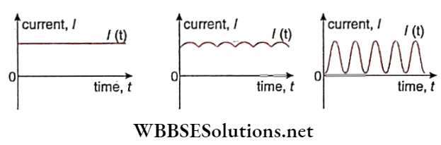
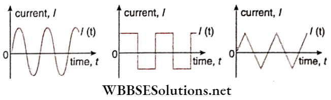
- In the graphs, different kinds of direct current concerning time are shown. Of these, the current shown in the is steady current the magnitude of current in this case always remains unchanged.
Alternating Current (ac): An electrochemical cell does not provide large amounts of electrical energy. All electric power plants use a machine called a dynamo or generator for this purpose.
- The characteristics of this machine are—the electrical nature of its two electrodes does not remain constant, but changes from positive to negative, and from negative to positive periodically.
- As a result, current through the external circuit connected to this source gets reversed periodically, i.e., the flow of current does not remain unidirectional.
- The electromotive force obtained from this source is called alternating emf and the current in the circuit is called alternating current.
- All modern electrical appliances, simple or delicate, are enabled. Hence the importance of the study of ac. Current-time graphs of some alternating currents are shown.
Read and Learn More Class 12 Physics Notes
The following characteristics of alternating current are to be noted.
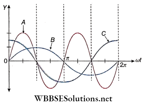
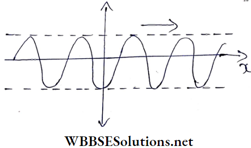
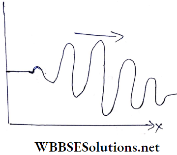
- An alternating current is of a wave nature.
- The magnitude of the current above the time axis is taken as positive, and that below is taken as negative. This implies that the direction of the current gets reversed periodically, and at the moment of this transition, the instantaneous magnitude of the current becomes zero.
- The waveforms of different alternating currents may be different. The waveforms of the three different currents shown are respectively sinusoidal, square, and triangular. Of them, the discussion about the sinusoidal waveform is of particular importance; because, by appropriate mathematical analysis, the square, triangular, or any other waveform can be reduced to a combination of a large number of sinusoidal waves.
Alternating Current Source Of Alternating Current Ac Dynamo
Almost the entire electrical energy requirement of the present-day world is derived from the phenomenon of electromagnetic induction.
The machine employing this phenomenon is called a dynamo or generator. A conducting coil is set to rotate inside a magnetic field, as a result of which a current is induced in the coil. This is the basic mechanism.
Definition: The machine in which the mechanical energy of a rotating conducting coil placed in a magnetic field is converted into electrical energy, is called a dynamo or generator.
Description: The main parts of an alternating current dynamo are shown.
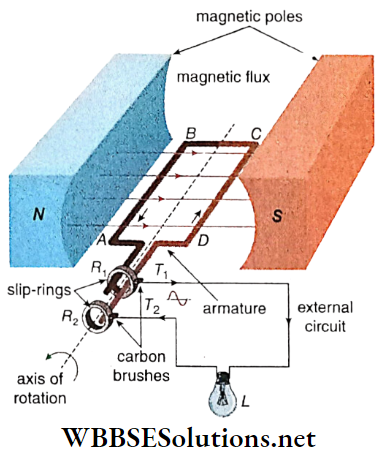
N, S: The poles of a strong horseshoe magnet which produces a uniform magnetic field directed from the north to the south pole in the gap between them. Some lines of force are shown in the figure. This magnet is called the field magnet.
ABCD: A rectangular coil called an armature is placed in a uniform magnetic field, which usually contains several turns.
The coil in this case is made to rotate about the axis normal to the magnetic field; the direction of rotation in this case is as shown in the diagram.
R1, R2: Two smooth brass rings called slip rings. They are connected to the coil at its open ends A and D.
T1, T2: Two carbon brushes fitted to the rings with the help of springs, which keep the brushes pressed against the rings R1 and R2.
L: An electric lamp, to indicate the presence of current.
Observation: The lamp glows as long as the coil rotates. From this, we can infer that an electric current is flowing through the external circuit attached to T1 and T2. As soon as the rotation of the coil ceases, the current stops and the lamp goes out.
WBBSE Class 12 Alternating Current Notes
Working Principle: when the coil ABCD arms AB and CD intersect the magnetic lines of force. As a result, electromagnetic induction takes place.
- At a certain moment, when the motion of the arm AB is downwards, according to Fleming’s right-hand rule, a current will be induced in the direction BA. At the same time due to the upward motion of the arm CD, the direction of induced current will be along DC.
- So, a current will be set up in the direction of DCBA in the coil and will flow from T1 to T2 in the external circuit In this situation T1 and T2 behave as the positive and negative poles of a battery, respectively.
- Here, arms BC and AD do not intersect the magnetic lines of force.
- When, after half-rotation, the positions of the arms AB and CD are interchanged, by applying Fleming’s right-hand rule, it is observed that current is now induced in the direction ABCD.
As a result, current flows in the second half of rotation from T2 to T1 in the external circuit. Thus, the polarities of T1 and T2 get reversed, reversing the direction of the current.
- This reversal of the direction of the current goes on periodically. Every time the coil crosses its vertical position, the direction of the current gets reversed. Hence, this dynamo is called an AC dynamo.
- Because the heating effect of electric current {αI2, i.e., the same for +I and -I) does not depend on the direction of current, the lamp continues to glow as long as the coil rotates.
- If a DC galvanometer (for example., a moving coil galvanometer) is placed instead of the electric lamp, no deflection of its pointer would be observed.
Factors Affecting The Emf And Current: The electromotive force, and hence the current is directly proportional to
- Area of the coil,
- Number of turns of the coil,
- speed of rotation of the coil and
- Strength of the magnetic field.
So, if any one of them is increased, the emf will also increase. The current however will decrease with an increase in the resistance of the circuit.
Electric motor: The principle of action of an electric motor is just opposite to that of a dynamo.
- A motor is a device in which a current-carrying coil, placed suitably in a magnetic field, rotates on the principle of action of magnets on currents.
- A motor converts the electrical energy of the coil into its mechanical energy.
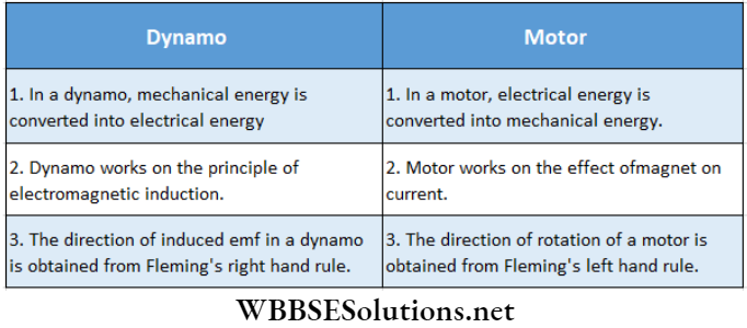
Differences Between Dynamo And Motor:
However, the discussions on both DC and AC motors are beyond our present syllabus.
WBCHSE Class 12 Physics Alternating Current Notes
Alternating Current Variation Of Alternating Current
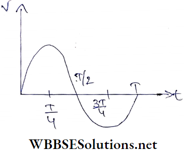
Waveform Of Alternating Current: Let a rectangular. coil ABCD is rotating with uniform angular velocity in a uniform magnetic field. The coil is viewed in a way such that only the AD end of the coil becomes visible. The different positions of this end concerning time are shown.
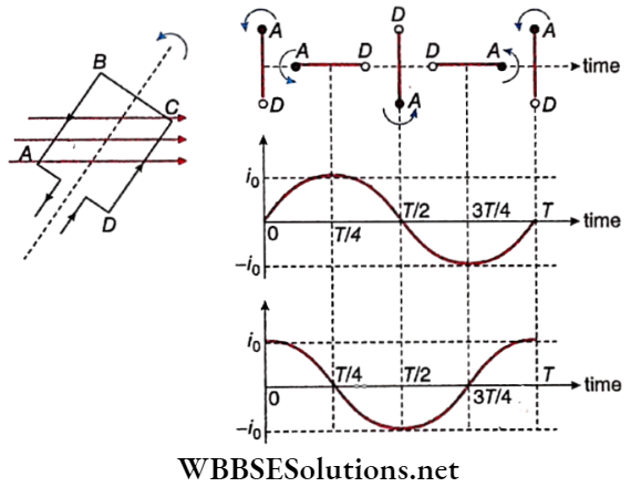
Let the period of the coil be T. If the coil starts rotating from its vertical position, then at \(\frac{T}{2}\) and T, it again comes to its vertical position.
At these moments both AB and CD are moving parallel to the magnetic field. Considering the equation, e = Blvsind with θ = 0° the induced emf and hence the induced current will be zero.
On the other hand, at the times \(\frac{T}{4}\) and \(\frac{3T}{4}\), the coil lies horizontally. At those positions,r. AB and CD are directed normally to the magnetic field (θ = 90°), and the induced current becomes maximum.
However, at the time \(\frac{T}{4}\), the direction of current is along DCBA, while at the time \(\frac{3T}{4}\), it is along ABCD. So, if the current in the first case is taken as positive, then the current in the second case will be negative.
This figure clearly shows a sine-wave; this is the wave nature of current if the coil starts rotating from its vertical position.
On the other hand, if the coil, starts rotating from its horizontal position, the current Will be a cosine-wave. Note that, both sine and cosine waves are called sinusoidal waves.
The current completes a cycle of change in a time equal to the period of rotation of the coil. A complete wave is thus formed in every cycle.
Expression Of Alternating Current: Let a rectangular coil be rotating with uniform angular velocity ω in a uniform. magnetic field B. At any moment t, the angle between the normal to the coil and the direction of the magnetic field is θ, say.
If the area of the plane of the coil is A, the magnetic flux linked with the coil,
Φ = BAcosθ → (1)
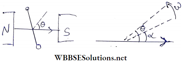
Initially, the angle between the normal to the plane of the coil and the direction of the magnetic field = α (say). After rotation for time t, this angle becomes,
θ = ωt + α
So, from equation (1) we get, magnetic flux,
Φ= BA cos (ωt+α) → (2)
Hence, the magnitude of the induced emf in the coil of a single turn
⇒ \(e=\frac{d \phi}{d t}=\omega B A \sin (\omega t+\alpha)\)
For N turns,
⇒ \(e=\omega B A N \sin (\omega t+\alpha)=e_0 \sin (\omega t+\alpha)\) → (3)
[here, e0 = ωBAN]
If the total resistance of the coil and the external circuit is R, the induced current,
⇒ \(i=\frac{e}{R}=\frac{\omega B A N}{R} \sin (\omega t+\alpha)=\frac{e_0}{R} \sin (\omega t+\alpha)\)
⇒ i0sin(ωt + α) → (4)
Phase: The state of alternating current at any moment is expressed by its phase. In equations (3) and (4), (ωt + α) is the phase of the alternating current.
Phase Difference: If the phases of two alternating currents are δ1 and δ2, then(δ1-δ2) is the phase difference of those two currents.
If co is the same for the two currents, the phase difference
becomes (α1– α2)
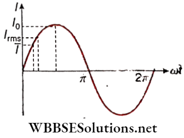
Peak Value: As -1 ≤ sinθ ≤ 1, it can be concluded that
- The maximum and minimum values of the electromotive force are e0 and -e0 respectively.
- Accordingly, the maximum and minimum values of the current are i0 and -i0.
These magnitudes, e0 and i0 are called the peak values of electromotive force and current.
Dependence Of Peak Value On Different Factors: it is obvious from equations (3) and (4) that the peak values of emf as well as current depend directly on each of the quantities involved, viz., co, B, A, N. Moreover, the peak value of current also varies inversely with the resistance (R) of the circuit.
Period And Frequency: The definite time interval in which a complete cycle repeats itself, is called the period (T) of an alternating current.
If the angular velocity, of the coil, is co, then
∴ \(T=\frac{2 \pi}{\omega}\) → (5)
The number of complete waves produced in unit time is called the frequency (n) of an alternating current.
So, \(n=\frac{1}{T}=\frac{\omega}{2 \pi}\) → (6)
Frequency is the most important quantity in the expression of an ac. It is noted that the frequency of domestic electric supply in India is 50 Hz or 50 cycles per second(cps). It indicates that the direction of the current is reversed (50 x 2) or 100 times per second.
Class 12 Physics Alternating Current Notes
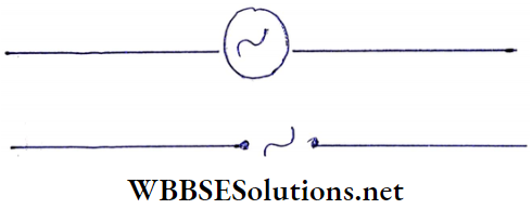
Alternating Current Circuit Symbol Of An AC Source
It represents the symbols of an AC source used in a circuit. Any of these symbols may be used for the purpose.
Average Values Of Alternating Voltage And Current
Alternating voltage (V) or Current (I) always increases, decreases, and changes periodically following the functions since or cos ωt. But the average values of these quantities, do riot change with time.
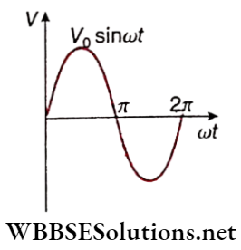
Calculation: Let an expression for sinusoidal alternating voltage,
V = V0 Sin ωt
Average value of it in a full cycle (i.e., for t = T)
= \(\frac{1}{T} \int_0^T V d t=\frac{1}{T} \int_0^T V_0 \sin \omega t d t=0\)
This is because the voltage in a half cycle is positive and in the next half it is of the same magnitude, but negative.
Short Notes on AC Circuits
For convenience, the average value in a half-cycle, instead of in a full-cycle, in ac is considered as the average value \((\bar{V})\) of an alternating voltage.
∴ \(\bar{V}=\frac{1}{T / 2} \int_0^{T / 2} V_0 \sin \omega t d t=\frac{2 V_0}{\omega T}[-\cos \omega t]_0^{T / 2}\)
= \(\frac{2 V_0}{\pi}=0.637 V_0\)
Similarly, the average value of alternating current,
∴ \(\bar{I}=\frac{2 I_0}{\pi}=0.637 I_0\)
Class 12 Physics Alternating Current notes RMS Values Of Alternating Voltage And Current
Alternating voltage or current cannot be measured directly with instruments like galvanometers. They can only be measured indirectly following the thermal effect of current.
We know that heat generated in a current-carrying conductor is directly proportional to V2 or l2, i.e., heat thus generated does not depend on the direction of the current.
- Due to the periodical changes of an alternating current, the heat in the conductor fluctuates from zero to a certain positive value. Hence the average value of heat should be proportional to the average value of V2 or I2.
- The value most commonly used for an ac is its effective value. The effective value of ac is the amount of ac that produces the same heating effect as an equal amount of dc.
- This is calculated by squaring all the amplitudes of the sine wave over one period, taking the average of these values, and then taking the square root.
The effective value, being the root of the average (or mean) of the square of the currents, is known as the root mean square (in short, rms) value.
Calculation: Let an expression for sinusoidal alternating voltage,
v = v0 sinωt
So, the mean square of V,
∴ \(\vec{V}^2=\frac{1}{T} \int_0^T V^2 d t=\frac{1}{T} \int_0^T \cdot V_0^2 \sin ^2 \omega t d t\)
= \(\frac{V_0^2}{2 T} \int_0^T(1-\cos 2 \omega t) d t=\frac{V_0^2}{2 T}\left[t-\frac{\sin 2 \omega t}{2 \dot{\omega}}\right]_0^T\)
= \(\frac{V_0^2}{2 T}\left(T-\frac{\sin 4 \pi}{2 \omega}+\frac{\sin 0}{2 \omega}\right)\) [∵ ωt = 2π]
= \(\frac{v_0^2}{2}\)
∴ rms value of V,
⇒ \(V_{\mathrm{rms}}=\sqrt{\bar{V}^2}=\sqrt{\frac{V_0^2}{2}}=\frac{V_0}{\sqrt{2}}=0.707 V_0\)
Similarly, rms value of I,
⇒ \(I_{\mathrm{rms}}=\frac{I_0}{\sqrt{2}}=0.707 I_0\)
i.e., rms voltage = 70.7% of peak voltage
and rms current = 70.7% of peak current
Relation between peak value, average value, and rms value of alternating voltage and current: From the above discussion we have,
⇒ \(\bar{V}=\frac{2 V_0}{\pi}=0.637 V_0\)
and \(V_{\mathrm{rms}}=\frac{V_0}{\sqrt{2}}=0.707 V_0\)
where V0 is the peak value of alternating voltage.
∴ \(V_{\mathrm{rms}}: \bar{V}=\frac{V_0}{\sqrt{2}}: \frac{2 V_0}{\pi}=\frac{\pi}{2 \sqrt{2}}\)
or, \(V_{\mathrm{rms}}=\frac{\pi}{2 \sqrt{2}} \bar{V}=1.11 \bar{V}\)
∴ \(V_{\text {rms }}>\bar{V}\)
Similarly, \(I_{\mathrm{rms}}>\bar{I}\)
This relation is shown graphically.
We know that the heating effect of electric current is directly proportional to I2. Hence ac ammeters and ac voltmeters, are designed based on the heating effect of current. They directly measure rms values of alternating current and voltage respectively.
Form Factor: The ratio of the rms value and the average value of alternating voltage or current is known as the form factor.
Thus form factor, \(f=\frac{V_{\mathrm{rms}}}{\bar{V}}=\frac{\frac{V_0}{\sqrt{2}}}{\frac{2 V_0}{\pi}}=\frac{\pi}{2 \sqrt{2}}=1.11\).
Note that, the above value of form factor applies only to sinusoidal voltage arid current. For different waveforms, the values of the form factor are different. For example, for a square wave
∴ \(V_{\mathrm{rms}}=V_0 \text { and } \bar{V}=V_0\)
∴ Form factor, \(f=\frac{V_{\mathrm{rms}}}{\bar{V}}=1\)
From the form factor of an alternating voltage or current an effective idea about the waveform can be obtained.
Effects Of Oil An Ac Or DC Currents On The Human Body: the three main factors that determine what kind of shock one experiences are the amplitude, frequency, and duration of the current passing through the body.
Direct current has zero frequency i.e., it has a constant amplitude. On the other hand, the peak value of an ac voltage (V0) is √2. times its rms value (Vrms), for example., a 220V ac supply is going 220√2 or 311 V (approx.) before coming down to zero.
So, one can get a 311V shock from a 220V-50Hz ac supply line for (50 x 2) hor 100 times per second. The calculation indicates the severity of electrocution from ac compared to that from the decision of average for the same duration of time.
Class 12 Physics Alternating Current notes
Alternating Current Circuit Symbol Of An AC Source Numerical Examples
Example 1. Equation of an ac is \(I=, 10 \sin \left(200 \pi t-\frac{\pi}{15}\right)\) ampere. Determine the frequency and peak value of the current.
Solution:
Comparing with the general equation of ac, I = I0 sin(ωt + α) we get,
the peak value of current, I0 = 10 A
and angular frequency, ω = 200 π Hz
∴ Frequency, \(I=\frac{\omega}{2 \pi}=\frac{200 \pi}{2 \pi}=100 \mathrm{~Hz}\)
Example 2. If an ac is represented by I = 100 sin 200 πt ampere, determine the peak value of the current and period.
Solution:
Comparing with the general equation of ac, I = I0 sin(ωt+α) we get,
the peak value of current, I0 = 100 A
and angular frequency, ω = 200π HZ
∴ Time period, T = \(T=\frac{2 \pi}{\omega}=\frac{2 \pi}{200 \pi}=0.01 \mathrm{~s}\)
Example 3. An alternating current having a peak value of 141 A Is used to heat a metal wire. To produce the same rate of heating effect, another constant current IA is used. What is the value of I?
Solution:
∴ \(I_{\mathrm{rms}}=\frac{I_0}{\sqrt{2}}=\frac{141 \mathrm{~A}}{\sqrt{2}}=100 \mathrm{~A}\)
If a steady DC I produces the same rate of heating, then I = Irms = 100A.
Example 4. The peak value of an alternating magnetic field B is 0.01 T and the frequency is 100 Hz. If a conducting ring of radius 1 m is held normal to the field, what emf will be induced in the ring?
Solution:
n = 100 Hz
∴ Time period, \(T=\frac{1}{n}=\frac{1}{100} \mathrm{~s}\)
The time taken by the field to increase from 0T to, 0.01 T is \(\frac{T}{4}=\frac{1}{400} \mathrm{~s}\).
Now the area, A = π. m2 = π m2
Hence induced emf,
∴ \(|e|=\frac{d \phi}{d t}=\frac{d}{d t}(B A)=A \frac{d B}{d t}\)
or, \(|e|=\pi\left(\frac{0.01-0}{\frac{1}{400}}\right)=4 \pi \mathrm{V}=12.57 \mathrm{~V}\)
Class 12 Physics Electromagnetic Induction And Alternating Current
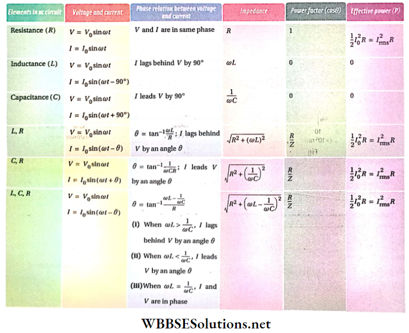
Alternating Current Power Consumed In Ac Circuits Some Important Ac Circuits
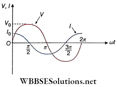
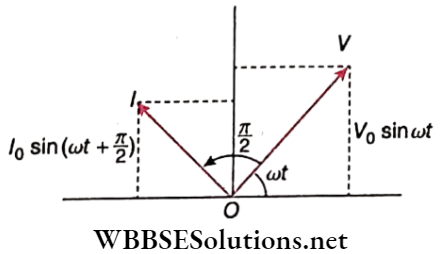
Power consumed In ac circuits: In any dc circuit, the potential difference (voltage) and the current are always in phase. But this is not so for ac circuits—in general, a phase difference is evolved between the voltage and the current Mathematically the voltage V and the current I are expressed as,
V = V0 sinωt and I = I0 sin(ωt-θ)
where, θ = phase difference between the voltage and the current. θ always lies between -90° and +90°, i.e., -90° ≤ θ ≤ 90°. Then, power consumed (or power dissipated) in the circuit is,
∴ \(P=V I=V_0 I_0 \sin \omega t \sin (\omega t-\theta)\)
= \(V_0 I_0 \sin \omega t[\sin \omega t \cos \theta-\cos \omega t \sin \theta]\)
=\(V_0 I_0\left[\sin ^2 \omega t \cos \theta-\sin \omega t \cos \omega t \sin \theta\right]\)
= \(V_0 I_0\left[\sin ^2 \omega t \cos \theta-\frac{1}{2} \sin 2 \omega t \sin \theta\right]\)
Over a complete cycle, the average of \(\sin ^2 \omega t=\frac{1}{2}\) and that of sin2ωt = 0. So the average power of the circuit is,
∴ \(\bar{P}=\frac{1}{2} V_0 I_0 \cos \theta=\frac{V_0}{\sqrt{2}} \frac{I_0}{\sqrt{2}} \cos \theta=V_{\mathrm{rms}} I_{\mathrm{rms}} \cos \theta\)
No experiment can measure the instantaneous power P; every measurement leads to the average power \(\bar{P}\). This \(\bar{P}\) is referred to as the effective power, and is usually denoted by the simple symbol P. So the effective power (or true power) of an ac circuit is,
∴ \(P=\frac{1}{2} V_0 I_0 \cos \theta=V_{\mathrm{rms}} I_{\mathrm{rms}} \cos \theta\) → (1)
Common Questions on Alternating Current
Power Factor: The factor cosθ in equation (1) is vitally important; this factor arises, clearly, due to the voltage-current phase difference θ. This cosθ is called the power factor of an ac circuit.
- If θ ≠ 0, cos θ< 1; so the power factor, in general, reduces the power consumed in an ac circuit to some extent Also, as -90°≤ θ ≤ 90°, the power factor cosθ is never negative; as a result, the power consumed in the circuit can never be negative.
- The unit of power P is watt (W); to distinguish between P and the product Vrms Irms, watt is never used as the unit of VrmsIrms — the usual unit of this product is volt. ampere or V.A.
- Incidentally, from the similarity with the dc expression P = VI, the product Vrms Irms is often called the apparent power of an ac circuit. Clearly,
true power = apparent power x power factor.
If voltage and current are in the same phase, then θ = 0 and cos θ = 1. In this condition, an ac circuit consumes the maximum power.
If the voltage and the current are either -90° or +90° out of phase, then cos θ = 0 and P = 0. An ac circuit of this type consumes no power. The corresponding current is referred to as wattless current.
Time Interval Between The Peak Values Of Voltage And Current:
v = v0 sinωt, I = I0sin(ωt-θ)
So, \(V=V_0, \text { when } \omega t=\frac{\pi}{2}, \text { i.e., } t=\frac{\pi}{2 \omega}\)
Similarly, \(I=I_0 \text {, when }\left(\omega t^{\prime}-\theta\right)=\frac{\pi}{2} \text {, i.e., } t^{\prime}=\frac{\pi}{2 \omega} 4 \frac{\theta}{\omega}\)
Thus, the minimum time interval between the peak values of ac voltage and current is,
∴ \(t_0=t^{\prime}-t=\frac{\theta}{\omega}\)
WBCHSE Physics Alternating Current study material Purely Resistive Circuit
shows the circuit. Alternating voltage applied in the circuit,
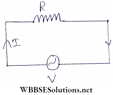
V = V0sinω t → (1)
Here, the peak value of alternating voltage = v0
rms value, vrms = \(\frac{V_0}{\sqrt{2}} ; \text { frequency, } f=\frac{\omega}{2 \pi}\).
According to Ohm’s law,
⇒ \(I=\frac{V}{R}=\frac{V_0}{R} \sin \omega t\)
Or, \(I=I_0 \sin \omega t\)
So, the peak value of ac, \(I_0=\frac{V_0}{R}\)
⇒ rms value, \(I_{\mathrm{rms}}=\frac{I_0}{\sqrt{2}}=\frac{V_0}{\sqrt{2} R}=\frac{V_{\mathrm{rms}}}{R}\);
⇒ frequency, \(f=\frac{\omega}{2 \pi}\)
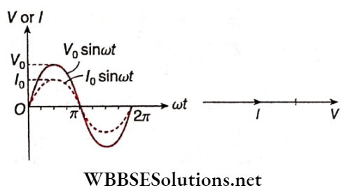
The factor sinωt in equations (1) and (2) indicates that
- Voltage and current are in phase;
- There is no change in frequency in this type of circuit.
Practice Problems on Alternating Current
Power in the circuit: Phase difference between voltage and current, θ = 0; so, power factor, cosθ = 1. For this, maximum power is consumed in a purely resistive circuit, which is
∴ \(P=\frac{1}{2} V_0 I_0 \cos \theta=\frac{1}{2}\left(I_0 R\right) I_0 \cdot 1=\frac{1}{2} I_0^2 R=\left(\frac{I_0}{\sqrt{2}}\right)^2 R\)
i.e., P = Irms2.R → (3)
Purely Inductive Circuit
shows this circuit. Let the alternating voltage applied in the circuit be,
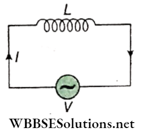
V = V0sin ωt → (1)
If the instantaneous change of current in the circuit is dl, the emf induced in the two ends of the inductor = \(-L \frac{d I}{d t}\)
This emf reduces the main voltage in the circuit. For this the effective voltage of the circuit = \(V_0 \sin \omega t-L \frac{d I}{d t}\).
A purely inductive circuit has no resistance i.e., R = 0. So according to Ohm’s law,
⇒ \(V_0 \sin \omega t-L \frac{d I}{d t}=0 \quad \text { or, } \frac{d I}{d t}=\frac{V_0}{L} \sin \omega t\)
or, \(\int d I=\int \frac{V_0}{L} \sin \omega t d t\)
or, \(I=-\frac{V_0}{\omega L} \cos \omega t+k\) [k = integration constant] → (2)
Dimensionally k is the same as I. Also, fc is a time-independent quantity. As the source voltage oscillates symmetrically about zero, the current also oscillates symmetrically about zero. For this, no constant or time-independent current can flow through the circuit, i.e., k = 0.
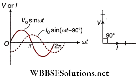
∴ \(I=-\frac{V_0}{\omega L} \cos \omega t=+\frac{V_0}{\omega L} \sin \left(\omega t-90^{\circ}\right)\)
or, I = I0sin(ωt-90°) →(3)
where \(I_0=\frac{V_0}{\omega L}\) = peak value of current.
From the equations (1) and (3) we come to the conclusions
current lags behind the voltage by 90°.
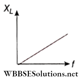
The quantity coL plays the same role in an inductive circuit as the resistance R in a resistive circuit. This quantity (i.e., ωL) is known as the inductive reactance of an ac circuit. Inductive reactance is the opposition offered by an inductor to the flow of alternating current through it. It is denoted by the symbol XL.
Hence for the above circuit,
XL = ωL = inductive reactance
Similar to that of R its unit is also ohm (Ω).
Power In The Circuit: Phase difference between voltage and current, θ = 90°, so, power factor, cosθ = 0.
Therefore, power consumption, \(P=\frac{1}{2} V_0 I_0 \cos \theta=0\)
The current I in this circuit is wattless.
WBCHSE Physics Alternating Current study material Purely Capacitive Circuit
shows the circuit. Alternating voltage applied in the circuit,
V = V0sin ωt →(1)
At any moment, if Q is the charge stored in the capacitor C, then its terminal potential difference is \(\frac{Q}{C}\)
This potential difference opposes the applied instantaneous voltage in the circuit.
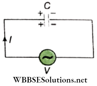
So, the effective voltage of the circuit, \(V_e=V_0 \sin \omega t-\frac{Q}{C}\)
As there is no resistance in the circuit, according to Ohm’s law, Ve = IR = 0
and hence, \(V_e=V_0 \sin \omega t-\frac{Q}{C}=0\)
or, Q = CV0sinωt → (2)
Therefore alternating current,
∴ \(I=\frac{d Q}{d t}=\omega C V_0 \cos \omega t=\omega C V_0 \sin \left(\omega t+90^{\circ}\right)\)
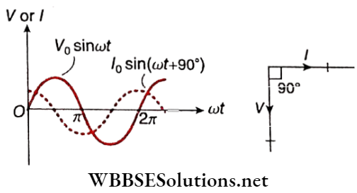
= I0sin(ωt+90°) → (3)
Where, \(I_0=\omega C V_0=\frac{V_0}{1 / \omega C}=\frac{V_0}{X_C}\) = peak value of current From the equations (1) and (3) we come to the conclusions
Current leads the applied voltage by 90°;
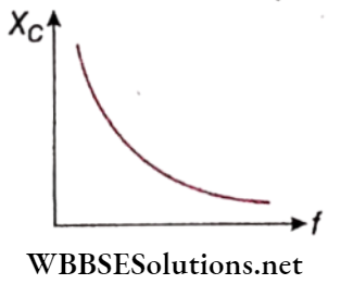
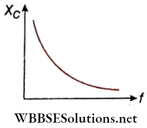
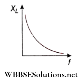
The quantity \(\frac{1}{\omega C}\)plays the same role in a capacitive circuit as the resistance R in a resistive circuit. This quantity (i.e., \(\frac{1}{\omega C}\) is known as capacitive reactance (XC).
Capacitive reactance is the opposition offered by a capacitor to the flow of alternating current through it. Hence for the above circuit.
∴ \(x_C=\frac{1}{\omega C}\) = capacity reactance
Similar to that of R or XL, its unit is also ohm (Ω).
Power In The Circuit: Phase’ difference between voltage and current, θ = -90°; so, power factor, cosθ = 0. Therefore, power consumption \(P=\frac{1}{2} V_0 I_0 \cos \theta=0\).
Here again, this current is wathers.
Wattless or Idle current: Power consumed in an ac circuit, \(P=\frac{1}{2} V_0 I_0 \cos \theta\). Now the phase difference between voltage and current in a pure inductive circuit, θ = 90°.
So power in the circuit is zero. On the other hand phase difference between voltage and current in a pure capacitive circuit, θ = -90°.
So, again power is equal to zero, which means, a purely inductive or capacitive circuit does not dissipate any power; current through the inductor or capacitor is hence called wattless or idle current.
LR Circuit
shows the circuit
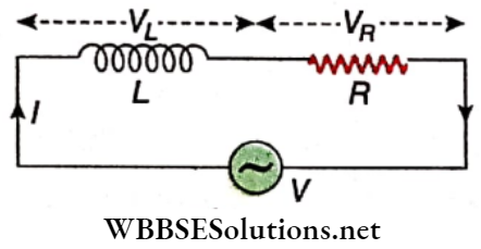
The applied alternating voltage,
V = V0sinωt → (1)
If the instantaneous change in current in of the circuit is dl, then the induced emf in the inductor \(L=-L \frac{d I}{d t}\);
i.e., the effective voltage in the circuit,
⇒ \(V_e=V_0 \sin \omega t-L \frac{d I}{d t}\)
According to Ohm’s law, Ve = IR, where the resistance, if any, of the inductor L is included in R.
∴ \(V_0 \sin \omega t-L \frac{d I}{d t}=I R\)
or, \(L \frac{d I}{d t}+R I=V_0 \sin \omega t\) → (2)
Let I = I0sin(ωt+ α)
or, \(\frac{d I}{d t}=\omega I_0 \cos (\omega t+\alpha)\)
So, putting the values of I and \(\frac{d I}{d t}\) in identity (2) we get
ωLI0 cos(ωt+α) + RI0 sin(ωt+α) = V0 sinωt
or, I0{R sin((ωt+ α) + L cos(ωt+α)} = V0 sinωt
or, \(I_0 \sqrt{R^2+(\omega L)^2}\{\frac{R}{\sqrt{R^2+(\omega L)^2}} \sin (\omega t+\alpha)+\frac{\omega L}{\sqrt{R^2+(\omega L)^2}} \cos (\omega t+\alpha)\}=V_0 \sin \omega t\)
or, \(I_0 Z\left\{\frac{R}{Z} \sin (\omega t+\alpha)+\frac{\omega L}{Z} \cos (\omega t+\alpha)\right\}=V_0 \sin \omega t \text { [where } Z=\sqrt{R^2+(\omega L)^2} \text { ] }\)
or, \(I_0 Z\{\sin (\omega t+\alpha) \cos \theta+\cos (\omega t+\alpha) \sin \theta\}=V_0 \sin \omega t \text { [where } \cos \theta=\frac{R}{Z} \text { and } \sin \theta=\frac{\omega L}{Z} \text { ] } \)
or, I0Zsin(ωt+ α + θ) = V0sin ωt
From this identity, comparing both sides we get,
⇒ \(I_0 Z=V_0 \quad \text { or, } I_0=\frac{V_0}{Z}=\frac{V_0}{\sqrt{R^2+(\omega L)^2}}\)
and α + θ = 0 or, α = -θ
So, the ac in the circuit,
∴ \(I=I_0 \sin (\omega t-\theta)=\frac{V_0}{Z} \sin (\omega t-\theta)\) → (3)
From equations (1) and (3) we conclude,
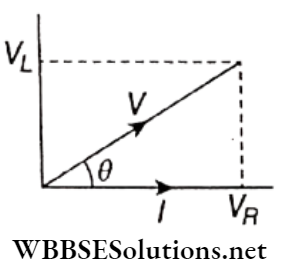
The current lags behind the applied voltage by a phase angle θ given by \(\tan \theta=\frac{\sin \theta}{\cos \theta}=\frac{\omega L}{Z} \times \frac{Z}{R}=\frac{\omega L}{R}\)
i.e., \(\theta=\tan ^{-1}\left(\frac{\omega L}{R}\right)\)
This phase relation is shown. We know that in a purely resistive circuit V and I are in the same phase i.e., phase difference, θ = 0. On the other hand, in a pure inductive circuit, I always lag behind V by θ = 90°. So in an LR circuit, I should lag behind V by 0 < θ < 90°.
In this circuit, Z plays the same role as R in a pure resistive circuit. Z is known as the impedance of an ac circuit.
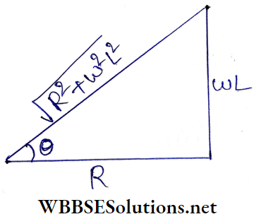
Impedance, \(Z=\sqrt{R^2+(\omega L)^2}=\sqrt{R^2+\left(X_L\right)^2}\) → (4)
where, XL = ωL = inductive reactance
Impedance in an LR circuit is the effective resistance of the circuit arising from the combined effects of ohmic resistance and inductive reactance.
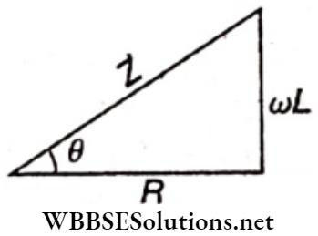
We can express the relation among R, XL, and Z with a suitable right-angled triangle. This triangle is called the impedance triangle.
Note that, R, ωL, and Z have, the same unit ohm(Ω).
Power In The Circuit:
Here, the power factor of the circuit, \(\cos \theta=\frac{R}{Z}\)
∴ \(P=\frac{1}{2} V_0 I_o \cos \theta=\frac{1}{2}\left(I_0 Z\right) I_0 \cdot \frac{R}{Z}=\frac{1}{2} I_0^2 R=\left(\frac{I_0}{\sqrt{2}}\right)^2 R\)
i.e., \(P=I_{\mathrm{rms}}^2 R\)
This means that the power is dissipated only in the resistance R. Current through the inductor is wattless.
CR Circuit
It shows the circuit. Alternating voltage applied to the circuit,
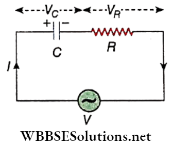
V = V0sin ωt → (1)
At any moment if Q is the charge stored in the capacitor C, then, the effective voltage in the circuit,
∴ \(V_e=V_0 \sin \omega t-\frac{Q}{C}\)
According to Ohm’s law
∴ \(V_0 \sin \omega t-\frac{Q}{C}=I R\)
or, \(R I+\frac{1}{C} Q=V_0 \sin \omega t\)
Now let us assume that Q = Q0 sin(ωt+ α)
∴ \(I=\frac{d Q}{d t}=\omega Q_0 \cos (\omega t+\alpha)\)
So, from the equation (2) we get,
∴ \(\omega R Q_0 \cos (\omega t+\alpha)+\frac{1}{C} Q_0 \sin (\omega t+\alpha)=V_0 \sin \omega t\)
or, \(\omega Q_0\left[R \cos (\omega t+\alpha)+\frac{1}{\omega C} \sin (\omega t+\alpha)\right]=V_0 \sin \omega t\)
or, \(\omega Q_0 Z\left[\frac{R}{Z} \cos (\omega t+\alpha)+\frac{1 /(\omega C)}{Z} \sin (\omega t+\alpha)\right]=V_0 \sin \omega t\)
[where \(Z=\sqrt{R^2+\left(\frac{1}{\omega C}\right)^2}\)(say)]
or, \(\omega Q_0 Z\{\cos (\omega t+\alpha) \cdot \cos \theta+\sin (\omega t+\alpha) \cdot \sin \theta\}=V_0 \sin \omega t\)
[where \(\frac{R}{Z}=\cos \theta \text { and } \frac{1 / \omega C}{Z}=\sin \theta\)(say)]
or, \(\omega Q_0 Z \cos (\omega t+\alpha-\theta)=V_0 \sin \omega t\)
or, \(\omega Q_0 Z \sin \left(\omega t+\alpha-\theta+90^{\circ}\right)=V_0 \sin \omega t\)
Comparing both sides we get,
∴ \(\omega Q_0 Z=V_0 \quad \text { or, } Q_0=\frac{V_0}{\omega Z}\)
and α – θ + 90° = 0 or, α = θ – 90°
So, alternating current in the circuit,
I = ωQ0cos(ωt+ α)
= \(\omega \frac{V_0}{\omega Z} \cos \left(\omega t+\theta-90^{\circ}\right)=\frac{V_0}{Z} \sin (\omega t+\theta)\)
i.e., \(I=I_0 \sin (\omega t+\theta)=\frac{V_0}{Z} \sin (\omega t+\theta)\) → (3)
Here, \(I_0=\frac{V_0}{Z}=\frac{V_0}{\sqrt{R^2+\left(\frac{1}{\omega C}\right)^2}}\)
From equations (1) and (3) we conclude the following.
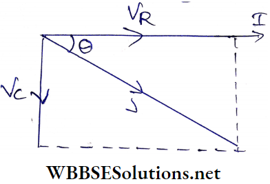
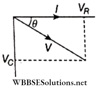
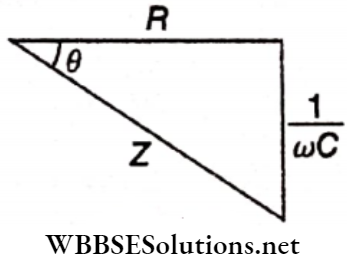
1. The current I leads the voltage V by a phase angle θ, where \(\tan \theta=\frac{\sin \theta}{\cos \theta}=\frac{1 / \omega C}{Z} \times \frac{Z}{R}=\frac{1}{\omega C R}\),
i.e., \(\theta=\tan ^{-1}\left(\frac{1}{\omega C R}\right)\)
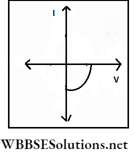
This phase relation is shown. We know that in a purely resistive circuit, V and I are in the same phase, i.e., phase difference, θ = 0. On the other hand, in a pure capacitive circuit, I always lead V by θ = 90°. So, in a CR circuit, I should lead V by 0 < θ < 90°.
2. Z plays the same role as R in a pure resistive circuit. This Z is known as the impedance of the circuit.
Impendance, \(Z=\sqrt{R^2+\left(\frac{1}{\omega C}\right)^2}=\sqrt{R^2+X_C^2}\) → (4)
where \(X_C=\frac{1}{\omega C}\) = capacitive reactance.
Impedance in a CR circuit is the effective resistance of the circuit arising from the combined effects of ohmic resistance and capacitive reactance.
shows the impedance triangle for the circuit.
Power In The Circuit: Here, the power factor of the circuit, \(\cos \theta=\frac{R}{Z}\)
so, \(P=\frac{1}{2} V_0 I_0 \cos \theta=\frac{1}{2}\left(I_0 Z\right) I_0 \cdot \frac{R}{Z}=\frac{1}{2} I_0^2 R=\left(\frac{I_0}{\sqrt{2}}\right)^2 R\)
∴ P = I2rms.R2
Hence, power is dissipated only in the resistance R . Current through the capacitor C is wattless.
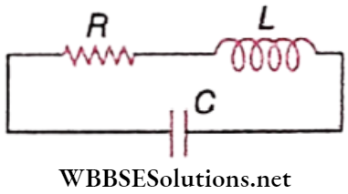
Series LCR Circuit
shows the circuit. Alternating voltage applied in the circuit,
V = V0sin ωt → (1)
If the instantaneous change in current in the circuit is dI, then the emf induced in the inductor
= \(-L \frac{d I}{d t}\).
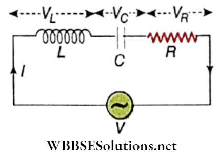
On the other hand, if Q is the instantaneous charge stored in the capacitor, the opposite emf thus developed in the circuit = \(-\frac{Q}{C}\).
So, the effective voltage in the circuit,
∴ \(V_e=V_0 \sin \omega t-L \frac{d I}{d t}-\frac{Q}{C}\)
According to Ohm’s law,
∴ \(V_0 \sin \omega t-L \frac{d I}{d t}-\frac{Q}{C}=I R\)
or, \(L \frac{d I}{d t}+R I+\frac{Q}{C}=V_0 \sin \omega t\)
Now, let us assume, Q = Q0sin(ωt+ α)
So, current, \(I=\frac{d Q}{d t}=\omega Q_0 \cos (\omega t+\alpha)\)
or, \(\frac{d I}{d t}=-\omega^2 Q_0 \sin (\omega t+\alpha)\)
Putting these values in equation (2) we get,
= \(-\omega^2 L Q_0 \sin (\omega t+\alpha)+\omega R Q_0 \cos (\omega t+\alpha)+\frac{Q_0}{C} \sin (\omega t+\alpha)=V_0 \sin \omega t\)
or, \(\omega Q_0\left\{R \cos (\omega t+\alpha)-\left(\omega L-\frac{1}{\omega C}\right) \sin (\omega t+\alpha)\right\}=V_0 \sin \omega t\)
or, \(\omega Q_0 Z\left\{\frac{R}{Z} \cos (\omega t+\alpha)-\frac{\omega L-1 / \omega C}{Z} \sin (\omega t+\alpha)\right\}=V_0 \sin \omega t\)
[Where \(Z=\sqrt{R^2+\left(\omega L-\frac{1}{\omega C}\right)^2}\)]
or, \(\omega Q_0 Z\{\cos (\omega t+\alpha) \cos \theta-\sin (\omega t+\alpha) \sin \theta\}=V_0 \sin \omega t=\)
[Where \(\frac{R}{Z}=\cos \theta \text { and } \frac{\omega L-1 / \omega C}{Z}=\sin \theta\)]
or, \(\omega Q_0 Z \cos (\omega t+\alpha+\theta)=V_0 \sin \omega t\)
or, \(\omega Q_0 Z \sin \left(\omega t+\alpha+\theta+90^{\circ}\right)=V_0 \sin \omega t\)
Comparing both sides we get,
⇒ \(\omega Q_0 Z=V_0 \quad \text { or, } Q_0=\frac{V_0}{\omega Z}\)
and α + θ + 90° = 0 or, α = -θ-90°
Then, cos(ωt+α) = cos(ωt- θ – 90°) = sin(ωt – θ)
So, alternating current in the circuit,
⇒ \(I=\omega Q_0 \cos (\omega t+\theta)\)
= \(\frac{V_0}{Z} \sin (\omega t-\theta)=I_0 \sin (\omega t-\theta)\) → (3)
Here \(I_0=\frac{V_0}{Z}=\frac{V_0}{\sqrt{R^2+\left(\omega L-\frac{1}{\omega C}\right)^2}}\) → (4)
From equations (1) and (3) we conclude,
Current lags behind voltage by a phase angle θ where \(\tan \theta=\frac{\sin \theta}{\cos \theta}=\frac{\frac{(\omega L-1 / \omega C)}{Z}}{\frac{R}{\bar{Z}}}=\frac{\omega L-\frac{1}{\omega C}}{R}\)
i.e., \(\theta=\tan ^{-1}\left(\frac{\omega L-\frac{1}{\omega C}}{R}\right)\) → (5)
This phase relation is shown. Now if VL < VC i.e., \(\omega L<\frac{1}{\omega C}\) will be negative. In such case, current I leads voltage V by angle θ. The voltage across the resistance R i.e., VR and current I are in the same phase. On the other hand, the current I lags behind VL by 90° but leads VC by a 90° phase angle.
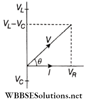
It is clear that M VL< VC i.e., if \(\omega L<\frac{1}{\omega C}\), I leads V by an angle θ.
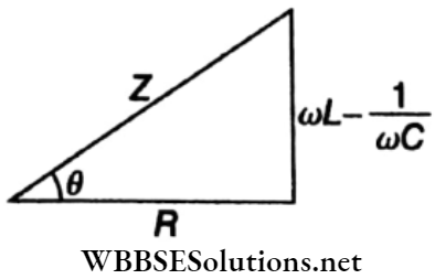
2. In an LCR circuit, Z plays the same role as R in a pure resistive circuit. So, Z is the impedance of the circuit.
Impedance, \(Z=\sqrt{R^2+\left(\omega L-\frac{1}{\omega C}\right)^2}=\sqrt{R^2+X^2}\)
where \(X=\omega L-\frac{1}{\omega C}=X_L-X_C\) = reactance of the circuit.
Impedance in an LCR circuit is the effective resistance of the circuit arising from the combined effect of ohmic resistance and reactance of the circuit.
shows the impedance triangle for the circuit.
Power In Series LCR Circuit:
Here, the power factor of the circuit, \(\cos \theta=\frac{R}{Z}\)
Therefore power consumed in the circuit
∴ \(P=\frac{1}{2} V_0 I_0 \cos \theta=\frac{1}{2}\left(I_0 Z\right) I_0 \cdot \frac{R}{Z}=\frac{1}{2} I_0^2 R=\left(\frac{I_0}{\sqrt{2}}\right)^2 R\)
i.e., P = I2rms R
This indicates that in this circuit power is dissipated neither in the inductor nor in the capacitor, but in the resistor only.
Hence currents through L or C are wattless.
The effective resistance of an LCR alternating current circuit is essentially the impedance of that circuit.
The inverse of impedance is known as admittance, i.e., admittance = \(\frac{1}{Z}\). Its unit is ohm” 1 or Siemens.
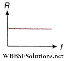
A pure resistance R opposes the current in any circuit and electrical energy is dissipated through it.
An inductive reactance XL and a capacitive reactance XC also oppose this current in a circuit, but no energy is dissipated through a pure inductor or a pure capacitor.
Both XL = coL and XC = depend on the frequency \(X_C=\frac{1}{\omega C}\) a) of the applied voltage. Clearly, for a dc voltage, (o = 0 . so that XL = 0, but XC = ∞. This means that dc passes freely through a pure inductor, but is blocked by a pure capacitor, which acts like an open switch.
Units of impedance and reactance: Both quantities have the same unit ohm (Ω).
Alternating Current Notes For Class 12 WBCHSE
Important Definitions in Alternating Current
Advantages Of The Capacitor Dependent Regulator Over A Resistor Dependent Regulator: In a resistor-dependent regulator the resistance also dissipates some energy which heats the regulator.
- On the other hand, only a capacitor but no resistor is used in an electronic regulator. Current in the circuit can be changed by regulating the capacitance of the capacitor and hence the speed of an electric fan can be controlled at will.
- As the current flowing through a pure capacitive ac circuit is wattless, such a regulator almost does not dissipate any power.
- So power is saved more in a capacitor-dependent regulator than in a resistor-dependent regulator. An electric regulator is useful in many devices—running an electric fan is just one of them.
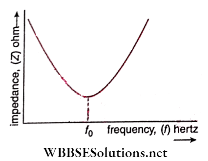
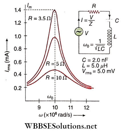
Series resonance: It is observed from equation (4) that for \(\omega L=\frac{1}{\omega C}\), the denominator becomes minimum, and hence the current I will be maximum. This phenomenon is called the series resonance of the LCR circuit. If f0 is the frequency for which the circuit reaches the above state, the condition for resonance, then
\(\omega_0 L=\frac{1}{\omega_0 C} \quad\left[\omega_0=2 \pi f_0\right]\) → (6)
i.e., \(\omega_0=\frac{1}{\sqrt{L C}}\)
or, \(f_0=\frac{\omega_0}{2 \pi}=\frac{1}{2 \pi \sqrt{L C}}\) → (7)
This frequency f0 is called resonant frequency. The particular frequency of current In an LCR series circuit for which inductive reactance (XL) and capacitive reactance (XC) become equal to each other is called resonant frequency.
Under this condition, the circuit is termed a resonant circuit. Thus, whatever the value of frequency other than f0, current I i.e., Irms is always less than its maximum value I.
The change of ac with angular frequency in an LCR circuit is shown graphically. It is known as the resonance curve. As \(I_m=\frac{V_0}{R}, I_m\) increases with the decrease of R.
Properties:
- In the case of resonance,
∴ \(\omega_0 L=\frac{1}{\omega_0 C} \text { or, } X_L=X_C\)
which indicates that the inductive and capacitive reactance balance each other. Hence the circuit becomes equivalent to a pure resistive circuit.
2. According to equation (5), for resonance,
∴ \(\tan \theta=\frac{0}{R}=0 \text { or, } \theta=0\)
i.e., in a resonance circuit, alternating voltage V and alternating current I are in equal phases. In this condition, according to equation (4) the maximum value of I0 i.e., Im = V0/R, which is equivalent to a pure resistive circuit.
3. LCR series circuit finds use in the receiver of a radio set. The resonant frequency of this LCR circuit is tuned with the frequency of the signal transmitted from a radio station.
Hence resonance occurs. As a result, the magnitude of the current increases a lot and the transmitted signal can easily be received. LCR series circuit is also known as acceptor circuit.
Sharpness Of Resonance And Q-Factor: Power consumed at LCR series circuit,
∴ \(P=\frac{1}{2} V_0 I_0 \cos \theta\)
where cosθ = power factor = \(\frac{R}{Z}\)
∴ \(P=\frac{1}{2} V_0 I_0 \cdot \frac{R}{Z}=\frac{1}{2} V_0 \cdot \frac{V_0}{Z} \cdot \frac{R}{Z}\)
= \(\frac{1}{2} V_0^2 \frac{R}{R^2+\left(\omega L-\frac{1}{\omega C}\right)^2}\) → (8)
At resonance, \(\omega=\omega_0 \text { and } \omega_0 L=\frac{1}{\omega_0 C}\) and as a result power dissipation becomes maximum. From equation (8) we come to the value of maximum power dissipation, i.e.,
∴ \(P_m=\frac{V_0^2 R}{2 R^2}=\frac{V_0^2}{2 R}\) → (9)
From (8) and (9) we get,
∴ \(P=P_m \cdot \frac{R^2}{R^2+\left(\omega L-\frac{L}{\omega C}\right)^2}\) → (10)
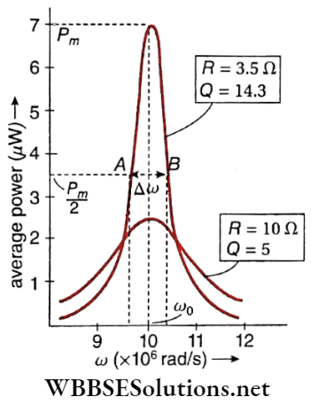
This shows the average power (P) versus frequency (ω) curve using the same circuit parameters.
The points A and B have some special importance. Each of these points denotes half maximum power \(\left(\frac{P_m}{2}\right)\).
The rapidity with which resonance phenomena arise and then disappear is a measurement of the sharpness of resonance. Resonance will be sharp if the value of bandwidth (Δω) is small.
This is of course possible only when the resonance curve falls steeply around ω = ω0.
Putting \(P=\frac{P_m}{2}\) in equation (10) we get,
= \(\frac{1}{2}=\frac{R^2}{R^2+\left(\omega L-\frac{1}{\omega C}\right)^2} \quad \text { or, }\left(\omega L-\frac{1}{\omega C}\right)= \pm R\)
or, \(\omega^2-\frac{1}{L C}= \pm \frac{R}{L} \omega\) → (11)
But we have \(\omega_0^2=\frac{1}{L C}\) (from series resonance condition)
Therefore from equation (11),
= \(\omega^2-\omega_0^2= \pm \frac{R}{L} \omega\)
i.e., \(\omega^2-\frac{R}{L} \omega-\omega_0^2=0 \quad \text { and } \omega^2+\frac{R}{L} \omega-\omega_0^2=0\)
Solving these quadratic equations neglecting the negative values of ω we get,
∴ \(\omega_1=\frac{R}{2 L}+\left(\omega_0^2+\frac{R^2}{4 L^2}\right)^{1 / 2}\)
and \(\omega_2=-\frac{R}{2 L}+\left(\omega_0^2+\frac{R^2}{4 L^2}\right)^{1 / 2}\)
Hence, bandwidth \((\Delta \omega)=\omega_1-\omega_2=\frac{R}{L}\) → (12)
and Q-factor = \(\frac{\omega_0}{\Delta \omega}=\frac{\omega_0 L}{R}=\frac{1}{\sqrt{L C}} \cdot \frac{L}{R}=\frac{1}{R} \sqrt{\frac{L}{C}}\) → (13)
Q-factor measures the sharpness of resonance in an LCR circuit. Inevitably, as Acy goes lesser, the Q-factor becomes greater and so resonance becomes sharper.
From equation (13), \(Q=\frac{\omega_0 L}{R}=\frac{X_L}{R}=\frac{I X_L}{I R}=\frac{V_L}{V_R}\)
where VL = voltage difference across inductor
and VR = voltage difference across the resistor
At resonance, VR = applied voltage ( V)
and VL = VC [VC = voltage difference across capacitor]
∴ \(Q=\frac{V_L}{V}=\frac{V_C}{V}\)
i.e., voltage difference (also called voltage drop) across inductor or capacitor concerning applied voltage in LCR series circuit is termed as Q-factor of the circuit.
The Q-factor is often much greater than 1. This means that in a series resonant circuit, VL and VC are much greater than the applied voltage V. This signifies a prominent voltage amplification across the inductor L and capacitor C.
Q-factor is a dimensionless parameter, which denotes the degree of damping of a resonator or oscillator. The more the value of Q, the less the rate of dissipation of energy concerning die energy stored, and the less the damping of the oscillator.
Alternating Current Power Consumed In Ac Circuits Numerical Examples
Example 1. In an LCR series ac circuit R = 10Ω, L = 50mH, and C = 5μV. Find out the resonant frequency and Q-factor. Find also the bandwidth and half-power frequencies.
Solution:
Here, L = 50mH = 5 x 10⁻²H;
C = 5μF = 5 X 10⁻⁶F
∴ Resonant frequency,
⇒ \(f_0=\frac{1}{2 \pi \sqrt{L C}}=\frac{1}{2 \times 3.14 \times \sqrt{\left(5 \times 10^{-2}\right) \times\left(5 \times 10^{-6}\right)}}\)
⇒ \(\frac{10^4}{2 \times 3.14 \times 5}=318.5 \mathrm{~Hz}\)
and Q-factor = \(\frac{1}{R} \sqrt{\frac{L}{C}}=\frac{1}{10} \sqrt{\frac{5 \times 10^{-2}}{5 \times 10^{-6}}}=\frac{1}{10} \times 100=10\)
Now, \(Q=\frac{\omega_e}{\Delta \omega}=\frac{f_0}{\Delta f}\)
∴ Bandwidth, \(\Delta f=\frac{f_0}{Q}=\frac{318.5}{10}=31.85 \mathrm{~Hz}\)
Half-power frequencies are,
⇒ \(f_1=f_0-\frac{\Delta f}{2}=318.5-\frac{31.85}{2}=302.6 \mathrm{~Hz}\)
and \(f_2=f_1+\frac{\Delta f}{2}=302.6+15.92=318.52 \mathrm{~Hz}\)
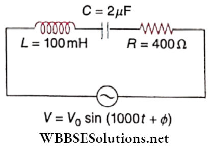
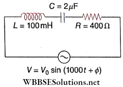
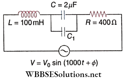
Example 2. In an LCR series combination, R = 400Ω, L = JOOmH, and C = 1 μF. This combination is connected to a 25 sin 2000t volt source. Find
- The impedance,
- Peak value of current,
- The phase difference of voltage and current,
- Power factor and
- Dissipated power in the circuit.
Solution:
Applied ac voltage V = 25 sin 2000 t volt
Peak value of voltage, V0 = 25V;
angular frequency, ω = 2000 Hz
and L = 100 mH = 0.1H
So, ωL = 2000 x 0.1 =200Ω
Here, \(C=1 \mu \mathrm{F}=10^{-6} \mathrm{~F} \quad \text { So, } \frac{1}{\omega C}=\frac{10^6}{2000}=500 \Omega\)
1. Impedance of the circuit,
∴ \(Z=\sqrt{R^2+\left(\omega L-\frac{1}{\omega C}\right)^2}\)
= \(\sqrt{(400)^2+(200-500)^2}=500 \Omega\)
2. Peak value of current, \(I_0=\frac{V_0}{Z}=\frac{25}{500}=0.05 \mathrm{~A}\)
3. If the phase difference between voltage and current is θ then,
∴ \(\tan \theta=\frac{\omega L-\frac{1}{\omega C}}{R}=\frac{200-500}{400}=-\frac{3}{4}=\tan \left(-36.9^{\circ}\right)\)
i.e., current leads voltage by a phase angle of 36.9°.
4. Power factor of the circuit,
∴ \(\cos \theta=\frac{R}{Z}=\frac{400}{500}=0.8\)
5. Power dissipated,
∴ \(P=\frac{1}{2} V_0 I_0 \cos \theta=\frac{1}{2} \times 25 \times 0.05 \times 0.8=0.5 \mathrm{~W}\)
Conceptual Questions on AC Waveforms
Example 3. The power factor of an LR circuit is \(\frac{1}{\sqrt{2}}\). If the frequency of ac is doubled, what will be the power factor?
Solution:
Power factor, \(\cos \theta=\frac{R}{Z}=\frac{1}{\sqrt{2}}\)
∴ Z2 = 2R2 or, R2 + (ωL)2 = 2R2 or, (ωL)2 = R2
Now if the angular frequency co is doubled,
(ω’L)2 = (2ωL)2 = 4(ωL)2 = 4R2
So, impendance, \(Z^{\prime}=\sqrt{R^2+\left(\omega^{\prime} L\right)^2}=\sqrt{R^2+4 R^2}=R \sqrt{5}\)
Hence, power factro, \(\frac{R}{Z^{\prime}}=\frac{R}{R \sqrt{5}}=\frac{1}{\sqrt{5}}\)
Example 4. f the value of inductor L is 1 mH and the applied ac source frequency is 50 Hz, find the inductive reactance in the above case.
Solution:
Here,1 = 1 mH = 10-3 H
and ω = 2πf= 2 x 3.14 x 50 = 314 Hz
∴ XL = ωL = 314 x 10-3 = 0.314 Ω
Example 5. A series LC circuit has L = 0.405-H and C = 25 μF. The resistance R is zero. Find the frequency of resonance.
Solution:
Here, L = 0.405 H, C = 25 μF = 25 x 10-6 F
∴ \(f_r=\frac{1}{2 \pi \sqrt{L C}}=\frac{1}{2 \times 3.14 \times \sqrt{0.405 \times 25 \times 10^{-6}}}=50 \mathrm{~Hz}\)
Example 6. An inductor and a capacitor of reactances 25Ω and 75Ω, respectively, are connected across a 250 V ac source in series. Find the potential difference between the inductor and the capacitor. Establish their relationship with the main voltage.
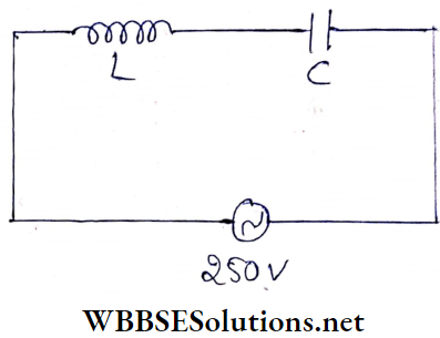
Solution:
The impedance of the series circuit having capacitor and inductor,
Z = XC-XL = (75-25) Ω = 50Ω
So, current, \(I=\frac{250}{50}=5 \mathrm{~A}\)
∴ Potential differences across the inductor,
VL = 5 x 25V = 125V
and potential differences across the capacitor,
VC = 5 x 75 V = 375 V
Now, main voltage,
V = 250 V
Hence, the relationship between V, VL and VC is
V = VC – VL
WBCHSE Class 12 Physics Chapter 7 Solutions
Example 7. A capacitor, a resistor of 5Ω, and an inductor of 50 mH are in series with an ac source marked 100 V, 50Hz. It is found that the voltage is in phase with the current. Calculate the capacitance of the capacitor and the impedance of the circuit.
Solution:
Since both the voltage and current of the circuit are in the same phase, the circuit is purely resistive. So impedance of the circuit, Z = R = 5 Ω
Frequency of the resonant circuit,
∴ \(f=\frac{1}{2 \pi \sqrt{L C}}\)
∴ \(C=\frac{1}{4 \pi^2 L f^2}=\frac{49}{4 \times 484 \times 50 \times 10^{-3} \times 50 \times 50}\)
= 2.03 x 10⁻⁴ F
Hence, the capacitance is 2.03 x 10⁻⁴ F and the impedance is 5Ω.
Example 8. A capacitor and a resistor are connected in series with an ac source. If the potential differences across C, R are 120 V, 90 V respectively and If the rms current of the circuit; is 3 A, calculate
- The impedance and
- The power factor of the circuit.
Solution:
Alternating voltage in the circuit,
∴ \(V=\sqrt{V_R^2+V_C^2}=\sqrt{90^2+120^2}=150 \mathrm{~V}\)
Now, current through the circuit, I = 3 A
- Impedance of the circuit, \(Z=\frac{\dot{V}}{I}=\frac{150}{3} \Omega=50 \Omega\)
- Power factor of the circuit, \(\cos \theta=\frac{V_R}{V}=\frac{90}{150}=0.6\)
Example 9. A 200μF capacitor in series with a 50 Ω resistor is connected to a 220 V, 50 Hz ac source.
- What is the maximum current in the circuit?
- What is the difference in time when the current and the voltage attain maximum values?
Solution:
Angular frequency of the source,
ω = 2πf=2 x 3.14 x 50Hz
C = 200μF = 2 x l0-4 F
Maximum current passing through the circuit
∴ \(I_0=\frac{V_0}{\sqrt{R^2+\frac{1}{C^2 \omega^2}}}\)
= \(\frac{\sqrt{2} \times 220}{\sqrt{(50)^2+\frac{1}{\left(2 \times 10^{-4}\right)^2 \times 4 \times(3.14)^2 \times(50)^2}}}\)
= 5.93 A
Now, if θ is the phase angle, then
= \(\tan \theta=\frac{1}{\omega C R}=\frac{1}{2 \pi f C R}=\frac{1}{2 \times 3.14 \times 50 \times 2 \times 10^{-4} \times 50}\)
= 0. 3185
or, \(\theta=\tan ^{-1}(0.3185)=17.67^{\circ}=\frac{17.67 \times \pi}{180} \mathrm{rad}\)
If the voltage and the current attain maximum value at a time different from t, then
θ = ωt
or, \(t=\frac{\theta}{\omega}=\frac{17.67 \times \pi}{180 \times 2 \pi \times 50}=9.82 \times 10^{-4} \mathrm{~s}\)
Example 10. A resistor, R = 300 Ω, and a capacitor, C = 25 μF are connected in series with an ac source. The peak value of voltage ( V0) and the frequency (f) of the source is 150 V and \(\frac{50}{\pi}\) Hz respectively. Find the peak value of the current and the power dissipated in the circuit.
Solution:
If ω is the angular frequency of the ac source; then
⇒ \(\frac{1}{\omega C}=\frac{1}{2 \pi \times \frac{50}{\pi} \times 25 \times 10^{-6}}=400 \Omega\)
Thus peak value of the current,
⇒ \(I_0=\frac{V_0}{\sqrt{R^2+\frac{1}{\omega^2 C^2}}}=\frac{150}{\sqrt{300^2+400^2}}=0.3 \mathrm{~A}\)
Hence, the power dissipated in the circuit
⇒ \(\frac{1}{2} I_0^2 R=\frac{1}{2} \times(0.3)^2 \times 300=13.5 \mathrm{~W}\)
WBCHSE Class 12 Physics Chapter 7 solutions
Example 11. A series LCR circuit containing a resistance of 120 Ω has an angular resonance frequency of 4 x 10⁵ rad/s. At resonance, the voltages across resistance and inductance are 60 V and 40 V, respectively. Find the values of L and C. At what frequency, does the current in the circuit lag behind the voltage by 45°?
Solution:
At resonance, XL = XC
∴ \(I=\frac{V_R}{R}\)
= \(\frac{60}{120}\) [voltage across the resistance, VR = 60 v]
= 0.5 A
Now, voltage across the inductor,
VL = IXL = IωL
∴ or, \(L=\frac{V_L}{I \omega}=\frac{40}{0.5 \times 4 \times 10^5}\) [∵ angular frequency, w = 4 x 10⁵ rad/s] [angular frequency, = 4 x 10⁵ rad/s]
= 2 x 10⁻⁴ H
We know that at resonance,
⇒ \(X_L=X_C \quad \text { or, } \omega L=\frac{1}{\omega C}\)
or, \(C=\frac{1}{\omega^2 L}=\frac{1}{\left(4 \times 10^5\right)^2 \times 0.2 \times 10^{-3}}=3.125 \times 10^{-8} \mathrm{~F}\)
Let the angular frequencyÿ ω1 when the current lags behind the voltage by 45°.
∴ \(\tan 45^{\circ}=\frac{\omega_1 L-\frac{1}{\omega_1 C}}{R}\) \(C=3.125 \times 10^{-8} \mathrm{~F}=\frac{1}{32} \times 10^{-6} \mathrm{~F}\)
or, \(1 \times 120=\omega_1 \times 2 \times 10^{-4}-\frac{1}{\omega_1\left(\frac{1}{32}\right) \times 10^{-6}}\)
or, \(\omega_1^2-6 \times 10^5 \omega_1-16 \times 10^{10}=0\)
The physically meaningful solution of the above equation is,
∴ \(\omega_1=\frac{6 \times 10^5+10 \times 10^5}{2}=8 \times 10^5 \mathrm{rad} / \mathrm{s}\)
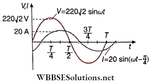
Example 12. In an LR series circuit, a sinusoidal voltage V = V0Sin ωt is applied. It is given that L = 35 mH, R = 11Ω, Vrms = 220V, \(\frac{\omega}{2 \pi}=50 \mathrm{~Hz} \text { and } \pi=\frac{22}{7}\). Find the amplitude of the current in the steady state and obtain the phase difference between the current and the voltage. Also, plot the variation of current for one cycle on the given graph.
Solution:
Inductive reactance,
∴ \(X_L=\omega L=(2 \pi)(50)\left(35 \times 10^{-3}\right) \approx 11 \Omega\)
Impedance, Z = \(\sqrt{R^2+X_L^2}=\sqrt{11^2+11^2}=11 \sqrt{2} \Omega\)
Given Vrms = 220V
Hence, amplitude of voltage, V0 = 2 Vrms = 22072 V
∴ Amplitude of current, \(I_0=\frac{V_0}{Z}=\frac{220 \sqrt{2}}{11 \sqrt{2}}=20 \mathrm{~A}\)
The phase difference between the current and the voltage in the circuit,
∴ \(\theta=\tan ^{-1}\left(\frac{X_L}{R}\right)=\tan ^{-1}\left(\frac{11}{11}\right)=\frac{\pi}{4}\)
In the LR circuit, voltage leads the current by phase angle θ. Thus current in the current circuit,
∴ \(I=I_0 \sin (\omega t-\theta)=20 \sin \left(\omega t-\frac{\pi}{4}\right)\)
Class 12 WBCHSE Physics Alternating Current Concepts
Alternating Current LG Oscillations
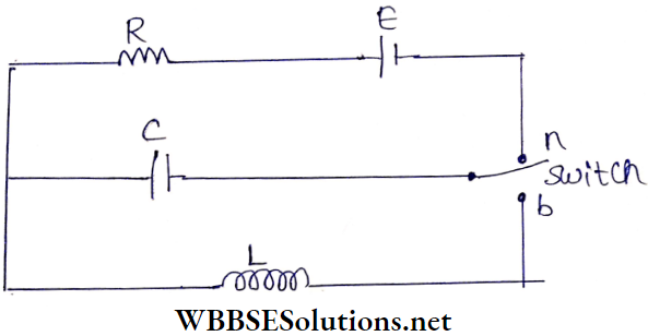
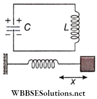
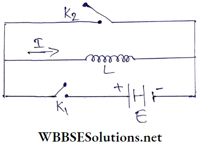
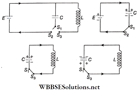
In the circuit shown, S1S2S3 is a two-way switch. To charge the capacitor C first, one has to connect the switch S1S2. If S1S3 is connected, the charged capacitor and the inductance L constitute an LC circuit.
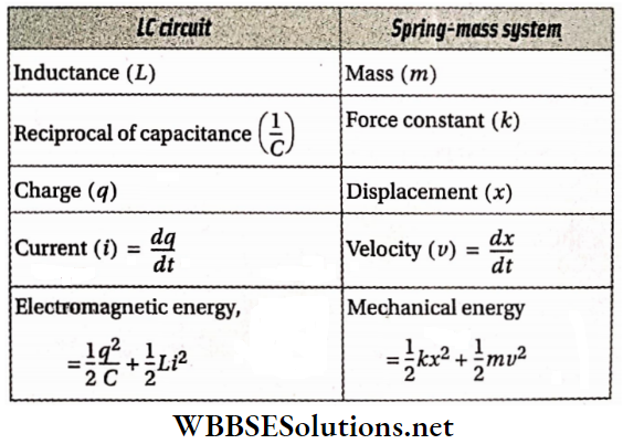
- As soon as the switch is disconnected from S2, no current flows through the circuit anymore. In this condition if the amount of charge in the capacitor C is Q, the energy stored in the electric field of the capacitor is \(E_C=\frac{1}{2} \frac{Q^2}{C}\), but the inductor possesses no energy, i.e., EL = 0.
- Due to the accumulation of charge in the capacitor, it acts as a battery. Hence immediately after connecting the switch S1S3, the capacitor starts to send current in the LC circuit thus forming.
- As this discharging current gradually rises, a magnetic field starts developing in the inductor. At this stage, it may be said that the capacitor is being discharged gradually through the inductor L.
- After some time, the capacitor C becomes completely discharged and the current of the LC circuit reaches a peak value I0 i.e., Ec becomes zero and \(E_L=\frac{1}{2} L I_0^2\).
It means that the electrical energy in the capacitor has been transferred fully into the magnetic energy in the inductor.
Again, due to the flow of current in the LC circuit, the capacitor is being charged in the reverse direction i.e., the capacitor is now charged with a polarity opposite to its initial state.
- Obviously with the increase of charge in the capacitor, the energy stored in its electric field begins to increase and the energy stored in the magnetic field of the inductance gradually decreases.
- Hence the magnitude of the current decreases and finally comes to zero. Thus after some time, EL becomes zero again, and \(E_C=\frac{1}{2} \frac{Q^2}{C}\). This process of discharging and charging of the capacitor occurs alternately.
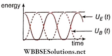
- We know that a capacitor can store electric energy whereas an inductor can store magnetic energy in it. Now a charged capacitor with an inductor is connected to an ac circuit, and a periodical energy transformation starts.
The energy of the capacitor is converted to the energy of the inductor and back again. This phenomenon is called LC oscillations.
In the above discussion, one half-cycle of this oscillation has been discussed. At the end of the next half-cycle, the circuit comes back to its initial condition.
- The polarity of the plates becomes equal to its initial state and the current circuit becomes zero again. The direction of the current in the second half cycle is just opposite to that in the first half cycle.
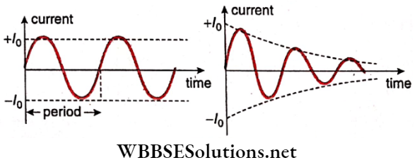
- So the current in an LC circuit fluctuates periodically between the peal values I0 and -I0.
- The resistance of a pure inductor is zero so there is no energy loss due to the Joule effect. So as time elapses, no loss of total energy takes place, i.e., there is no damping of LC oscillations.
- So the peak value of the alternating current in the LC circuit remains unchanged. But practically, the resistance of any coil cannot be ignored. Thus, there is always some resistance in the circuit due to which some energy is lost in the form of heat.
- So the current remains oscillatory, but is damped, To maintain the alternating current, the circuit must be supplied with the same amount of energy as is being lost during each cycle, from some external source.
- If damping is absent, the frequency of LC oscillations, \(f=\frac{1}{2 \pi \sqrt{L C}}\). When this frequency becomes equal to the frequency of the applied alternating emf then resonance occurs in that circuit.
Oscillators convert direct current (dc) from a power supply to an alternating current signal. LC circuits are used in many cases as an important component of an oscillator.
Class 12 Physics Electromagnetic Induction And Alternating Current Chapter 2 Alternating Current LG Oscillations Numerical Examples
Example 1. A 220 V, 50 Hz ac source is connected to an inductance of 0.2H and a resistance of 20 Ω in series. What is the current in the circuit?
Solution:
rms value of current, \(I_{\mathrm{rms}}=\frac{E_{\mathrm{rms}}}{\sqrt{R^2+(\omega L)^2}}\)
Here, = 220 V,
ω = 2πf = 2 x 3.14 x 50 = 314 Hz
∴ \(\sqrt{R^2+(\omega L)^2}=\sqrt{(20)^2+(314 \times 0.2)^2}\)
∴ \(I_{\mathrm{rms}}=\frac{220}{\sqrt{(20)^2+(314 \times 0.2)^2}}=3.34 \mathrm{~A}\).
Example 2. An ac source of frequency 50 Hz is connected with a resistance (R = 36Ω) and L of 0.12 H in series. What is the phase difference between current and voltage?
Solution:
If θ is the phase difference, then
∴ \(\tan \theta=\frac{\omega L}{R}\)
or, \(\theta=\tan ^{-1} \frac{\omega L}{R}=\tan ^{-1} \frac{314 \times 0.12}{36}=\tan ^{-1}(1.047)=46.3^{\circ}\)
[here ω = 2π x 50 = 2 x 3.14 x 50 = 314 Hz]
So, phase difference = 46.3°.
Example 3. A current of 1 A flows in a coil when connected to a 100 V dc source. If the same coil is connected to a 100 V, 50 Hz ac source, a current of 0.5 A flows in the coil. Calculate the inductance of the coil.
Solution:
If R is the resistance of the coil, in dc circuit \(\frac{E}{I}=R\)
or, \(R=\frac{100}{1}=100 \Omega\)
In ac circuit, \(I_{\mathrm{rms}}=\frac{E_{\mathrm{rms}}}{\sqrt{R^2+(\omega L)^2}}\)
or, \(\sqrt{R^2+(\omega L)^2}=\frac{E_{\mathrm{rms}}}{I_{\mathrm{rms}}}=\frac{100}{0.5}=200 \Omega\)
∴ R2 + (ωL)2 = (200)2
or, \(\omega L=\sqrt{(200)^2-(100)^2}=100 \sqrt{3} \Omega\)
or, \(L=\frac{100 \sqrt{3}}{\omega}=\frac{100 \times 1.732}{2 \times 3.14 \times 50}=0.55 \mathrm{H}\)
Real-Life Scenarios in AC Circuits
Example 4. A lamp in which 10 A current can flow at 15 V is connected with an alternating source of potential 220 V and frequency 50 Hz. What should be the inductance of the choke coil required to light the bulb?
Solution:
Resistance of the lamp, \(R=\frac{15}{10}=1.5 \Omega\)
To send 10 A current through the lamp, the required impedance of the ac circuit, \(Z=\frac{220}{10}=22 \Omega\)
Now if L is the inductance of the choke coil and its resistance is negligible, then
∴ \(Z=\sqrt{R^2+(\omega L)^2} \text { or, } \omega L=\sqrt{Z^2-R^2}\)
∴ \(L=\frac{1}{\omega} \sqrt{Z^2-R^2} ;[\omega=2 \pi f=2 \times 3.14 \times 50=314 \mathrm{~Hz}]\)
= \(\frac{1}{314} \sqrt{(22)^2-(1.5)^2}=0.07 \mathrm{H}\)
Example 5. What will be the peak value of alternating current when a condenser of 1 μF is connected to an alternating voltage of 200 V, 60 Hz?
Solution:
c = 1μF = 10-6F; ω = 2πf = 2 x 3.14 x 60 Hz
Peak value of current,
\(I_0=I_{\mathrm{rms}} \times \sqrt{2}=\frac{E_{\mathrm{rms}}}{\frac{1}{\omega C}} \cdot \sqrt{2}=E_{\mathrm{rms}} \cdot \omega C \sqrt{2}\)
= 200 x (2 x 3.14 x 60) x 10-6 x 1.414
= 0.106 A (approx.)
Class 12 WBCHSE Physics Alternating Current concepts
Alternating Current Transformer
The electrical appliance used to increase or decrease alternating voltage is called a transformer.
The transformer, which increases the voltage is called a step-up transformer, and the transformer used to decrease the voltage is called a step-down transformer.
Transformer works on the principle of mutual induction between a pair of colls.
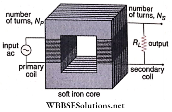
Description: The core of a transformer is constructed by several thin laminated sheets of soft iron placed one Over the other. It is known as a laminated core.
A core of a special shape is so chosen that no part of the magnetic flux is wasted and hence the density of lines of induction inside the core becomes maximum. Two insulated wires are wound in many turns on the middle arm of the core very close to each other.
Open coil acts as the primary (P) and the other as the secondary (S).
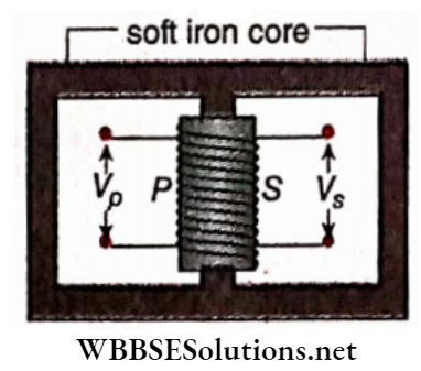
Working Principle: An alternating voltage (Vp) is applied to the primary coil from an alternating current source.
The alternating current in coil P generates induced emf in the secondary coil S, i.e., an alternating voltage Vs is generated between the ends of S.
If the dissipation of magnetic flux and loss of energy due to heating is neglected in this transformer (called an ideal transformer), it can be proved that,
∴ \(\frac{V_s}{V_p}=\frac{N_s}{N_p}=k\)
where Np and Ns are the total numbers of turps of the primary and secondary coils, respectively, and k is called the turns ratio or transformer ratio.
- Because of the special nature of the winding, it can be assumed fairly correctly that the magnetic flux ΦB associated with each turn of primary and secondary is the same. If e is the induced emf in each turn, \(e=-\frac{d \phi_B}{d t}\).
- Hence the emf induced in the primary oil \(V_p=N_p e=-N_p \frac{d \phi_B}{d t}\). Similarly, \(V_s=-N_s \frac{d \phi_B}{d t}\). Now, the emf induced in the primary must necessarily be equal to the voltage applied. Then, by dividing the two \(\frac{V_s}{V_p}=\frac{N_s}{N_{\dot{p}}}=k\).
If Ns > Np, i.e., k > 1, Vs > Vp we get a step-up transformer.
If Ns < Np, i.e., k < 1, Vf < Vp we get a step-down transformer.
Uses: Transformers are widely used in our daily lives. With its help, a high voltage can be converted into a low voltage and vice versa, whenever necessary. For example,
- An electrical power station uses a step-up transformer to produce and transmit large amounts of ac electrical energy over long distances.
- The energy is transmitted at high voltage (such as 66000V- 132000 V) to reduce the loss of energy due to heating.
- But supply to domestic area needs low voltages (such as 110 V-440 V). Such conversions of voltage at different levels are facilitated by step-down, transformers.
- Radio, television, electric bell,s and other electrical appliances require small-sized transformers.
Energy Loss In Transformer: In an ideal transformer, the power dissipated in the primary coil (IpVp) = power dissipated in the secondary coil (IsVs).
But no transformer, in practice, is ideal. Generally, Some input energy is wasted in any transformer and hence VsIs < VpIp .The term VsIs / VpIp is called the efficiency of a transformer.
The main causes of energy loss and their remedies are given below.
- Copper Loss: Generally copper wire is used to make primary and secondary coils. Due to Joule’s heating, some energy is wasted as heat energy.
- Remedies: Thick wire should be used to reduce this loss of energy.
- Iron Loss: Iron core should be used in primary and secondary cords.
- Due to the eddy current in this core, energy loss is unavoidable.
- Remedies: To reduce such loss, a laminated core is used.
- The change of magnetization cycle in the core fails to synchronize with ac and some energy is necessarily wasted in the core—known as hysteresis loss.
- Remedies: Due to high coercivity, the core should not be made of steel. The iron core is more effective, in reducing energy loss.
- Loss due to magnetic flux leakage: The flux generated by the primary coil may not be wholly linked to the secondary coil due to possible defective design of the core.
- Remedies: Obviously, special care should be taken in the construction of the core.
Classification Of Transformer: The two most common designs of the transformer are given below:
Core-Type Transformer: In this type, primary and secondary coils are wound around the core ring. Here every limb is occupied with both primary and secondary winding placed successively around them.
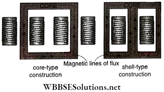
Shell-Type Transformer: Here the primary and secondary windings pass inside the steel magnetic circuit (core) which forms a shell around the windings, The main frame is constructed with three limbs. Both the primary and secondary windings are wound around the central limb.
Besides these, transformers can be classified based on their and these are audio frequency transformers, radio frequency transformers, etc.
Class 12 WBCHSE Physics Alternating Current concepts
Alternating Current Transformer Numerical Example
Example 1. The number of turns in the primary aid secondary coils of an ideal transformer is 140 and 280, respectively. If the current through the primary coil is 4 A, what will be the current in the secondary coil?
Solution:
In an ideal transformer, the secondary and primary coils are equal,
i.e. VsIs ± VpIp
∴ \(I_s=I_p \cdot \frac{V_p}{V_s}=I_p \cdot \frac{N_p}{N_s}=4 \times \frac{140}{280}=2 \mathrm{~A}\)
Example 2. The initial voltage and Input power of a transformer of efficiency 80% are 100 V and 4 kW, respectively. If the voltage of the secondary coil Is 200 V, determine the currents flowing through the primary and the secondary coil.
Solution:
Power of the primary coil i.e., input power
Pp = VpIp
or, \(I_p=\frac{P_p}{V_p}=\frac{4 \times 1000}{100}=40 \mathrm{~A}\)
Power of the secondary coil, \(P_s=P_p \times \frac{80}{100}\)
Again, Ps = VsIs
So, \(I_s=\frac{P_s}{V_s}=\frac{80}{100} \times \frac{P_p}{V_s}=\frac{80}{100} \times \frac{4 \times 1000}{200}=16 \mathrm{~A}\)
Alternating Current Very Short Questions And Answers
Properties Of Alternating Voltage And Current
Question 1. If the frequency of an alternating emf is 50 Hz, how many times the direction of emf will be reversed per second?
Answer: 100
Question 2. What percentage of its peak value is the rms value of an ac?
Answer: 70.7
Question 3. What is the peak value of the voltage of a 220 V ac line?
Answer: 311 V
Question 4. If an alternating current is represented by I = sin l00 π mA, what is its peak value?
Answer: 1 mA
Question 5. If an alternating current is represented by, I = sin 100 πt mA, then what is the frequency of that current?
Answer: 50 Hz
Question 6. After what time will the direction of current in an electric supply of frequency 50 Hz be reversed?
Answer: 0.01 s
Question 7. An alternating source of emf E = E0 sinwt and negligible resistance is connected directly to an ac voltmeter. What reading will it show?
Answer: \(\left[\frac{E_0}{\sqrt{2}}\right]\)
Question 8. What changes are observed in the rms value of an ac with changes in the frequency
Answer: No change
Question 9. What is the rms value of an alternating current, I = I0 sin ωt?
Answer: \(\left[\frac{I_0}{\sqrt{2}}\right]\)
Question 10. What is the ratio between the peak value and the average value of a sinusoidal emf?
Answer: \(\left[\frac{\pi}{2}\right]\)
Question 11. The instantaneous i current in an ac circuit is I = 6 sin 314t A. What is the rms value of current?
Answer: 4.24 A
Question 12. An alternating current is I = cos 100 πt A. Find out its frequency, peak value, and rms value.
Answer: 50 Hz, 1 A, 0.707 A
Examples of Applications of Alternating Current
Question 13. Why a dc voltmeter and dc ammeter cannot read ac?
Answer: The average is zero in a cycle
Question 14. What will be the phase difference between current and emf when 220 V, 50 Hz ac source is connected to a circuit containing pure resistor?
Answer: Zero
Series AC Circuits With R, L, C
Question 15. What is the unit of impedance?
Answer: ohm
Question 16. What is the reactance of pressure resistances in an ac circuit?
Answer: Zero
Question 17. If an LCR circuit is connected to a dc source, what will be the current through the circuit?
Answer: zero
Question 18. What will be the reactance if a current of frequency f flows through an inductor of self-inductance L?
Answer: 2 π fL.
Question 19. What will be the reactance if a current of frequency f flows through a capacitor of capacitance C?
Answer: \(\left[\frac{1}{2 \pi f C}\right]\)
Question 20. If the frequency of an ac circuit is increased, how would the reactance of an inductor change?
Answer: Increase
Question 21. If the frequency of an ac circuit is increased, how would the reactance of a capacitor change?
Answer: Decrease
Question 22. In an LR circuit, the alternating current ________ the alternating emf by a phase current the alter angle.
Answer: Lags behind
Question 23. In a CR circuit, the alternating current ________ the alternating emf by a certain phase angle.
Answer: Lead
Question 24. In an alternating series LCR circuit, what is the phase difference between the voltage drops across L and C?
Answer: 180
Question 25. When does the LCR series circuit have minimum impedance?
Answer: At resonance
Question 26. What is the reactance of a capacitor of capacitance C at f Hz?
Answer: \(\left[-\frac{1}{2 \pi f C}\right]\)
Power In Ac Circuits
Question 27. What is the power factor of a circuit having pure resistance only?
Answer: Zero
Question 28. What is the power dissipated in an ac circuitin which voltage and current are given by \(V=230 \sin \left(\omega t+\frac{\pi}{2}\right)\) and I = I0 sinωt?
Answer: Zero
LC Oscillations
Question 29. What is the natural frequency of an LC oscillator?
Answer: \(\left[\frac{1}{2 \pi \sqrt{L C}}\right]\)
Ac Generator And Transformer
Question 30. Indicate the change in emf produced by an ac dynamo in the following cases:
- The magnetic field is doubled,
- The angular velocity of the coil is decreased.
Answer: Will be doubled, will decrease
Question 31. If the area of the coil of an ac dynamo is halved, how would the emf generated change?
Answer: Halved
Question 32. If the angular velocity of the coil of an ac dynamo is doubled, how would the emfproduced change?
Answer: doubled
Question 33. By what factor would the output voltage of an ac generator change, if the number of turns in its coil is doubled?
Answer: 2
Question 34. The turns ratio of an ideal transformer is 4: 1. What will be the current in the secondary if that in the primary is 1.2A?
Answer: 4.8 A
Alternating Current Derivations For Class 12 WBCHSE
Alternating Current Synopsis Conclusion
In a dynamo, mechanical energy is converted into electrical energy.
In an electric motor, electric energy is converted into mechanical energy.
- The current whose direction in an electrical circuit reverses periodically in a definite time interval is called alternating current.
- The emf or potential difference whose direction reverses periodically in a definite time interval is called alternating emf or alternating potential difference.
- The electrical machine used to increase or decrease an alternating voltage is called a transformer. The transformer which increases the voltage is called a step-up transformer and which decreases the voltage is called a step-down transformer.
- The amount of power dissipation in any part of an AC circuit depends not only on ac voltage and current but also on their phase difference.
- The inductor or capacitor in an ac circuit resists the current just like a resistor. This resistance is called reactance. The pure resistance, inductive reactance, and capacitive reactance do not remain in the same phase.
The effective resistance against current in an ac circuit due to a combination of pure resistance, inductive reactance, and capacitive reactance is known as the impedance of the circuit. The magnitude of this impedance depends on the ac voltage and current.
- With the change of ac voltage frequency current also changes simultaneously.
- The frequency for which current becomes maximum is known as resonant frequency.
- In an LC circuit periodic interchange occurs between the stored energy in the electric field of the capacitor and that in the magnetic field of the inductor. This is LC oscillation.
- The power factor ofpure resistor is 1 i.e., it is the resistance that dissipates maximum power.
- The power factor of a pure inductor or capacitor is zero, i.e., they do not dissipate any power. Current through them is called wattless.
The emf induced in a coil rotating with uniform angular velocity ω in a uniform magnetic field intensity B, about an axis perpendicular to the field is,
e = NABω sin(ωt+ α) = e0sin (ωt+α)
[The coil is of cross-sectional area A having N turns]
If the total resistance of the coil and the external circuit is R, the induced current
∴ \(i=\frac{e}{R}=\frac{\omega B A N}{R} \sin (\omega t+\alpha)=\frac{e_0}{R} \sin (\omega t+\alpha)\)
= i0sin(ωt+ α)
Equation of an alternating emf,
V = V0sin(ωt+ α) where V0 = ωABN
Equation of an alternating current,
∴ \(I=\frac{V}{R}=\frac{V_0}{R} \sin (\omega t+\alpha)=I_0 \sin (\omega t+\alpha)\)
The average values of alternating voltage and current are respectively,
∴ \(\bar{V}=\frac{2 V_0}{\pi} \text { and } \bar{I}=\frac{2 I_0}{\pi}\)
rms values of the alternating voltage and current are respectively,
∴ \(V_{\mathrm{rms}}=\frac{V_0}{\sqrt{2}} \text { and } I_{\mathrm{rms}}=\frac{I_0}{\sqrt{2}}\)
Form factor for a sinusoidal wave, \(f=\frac{V_{\mathrm{rms}}}{\bar{V}}=\frac{\pi}{2 \sqrt{2}}=1.11\)
If the number of turns in the primary coil of a transformer = Np, the number of turns in its secondary coil = Ns, and the ratio of the number of turns = k, then in the case of an ideal transformer,
∴ \(\frac{I_p}{I_s}=\frac{V_s}{V_p}=\frac{N_s}{N_p}=k\)
In an ideal transformer, input power (VpIp) = Output power ( VsIs ).
The efficiency of a transformer = \(\frac{V_s I_s}{V_p I_p}\); the efficiency of an ideal transformer = 1 or 100%.
Inductive reactance, XL = ωL.
Capacitive reactance, \(X_C=\frac{1}{\omega C}\)
The impedance of an LCR series circuit,
∴ \(Z=\sqrt{R^2+\left(\omega L-\frac{1}{\omega C}\right)^2}\)
In an LCR series circuit, if ac voltage V = V0 sin ωt then alternating current, I = I0 sin(ωt- θ),
Where \(\dot{I}_0=\frac{V_0}{Z} \text { and } \tan \theta=\frac{\omega L-\frac{1}{\omega C}}{R}\)
Condition for resonance in an LCR series circuit,
∴ \(\omega L=\frac{1}{\omega C}\)
Resonant frequency, \(f_0=\frac{1}{2 \pi \sqrt{L C}}\)
Effective voltage magnification for series resonance,
∴ \(Q=\frac{V_L}{V_R}=\frac{V_C}{V_R}=\frac{\omega_0 L}{R}=\frac{1}{\omega_0 C R}=\frac{1}{R} \sqrt{\frac{L}{C}}\)
The natural frequency of an LC oscillator,
∴ \(f=\frac{1}{2 \pi \sqrt{L C}}\)
Power dissipation in an ac circuit
= \(V_{\mathrm{rms}} I_{\mathrm{rms}} \cos \theta\)
where cos θ = power factor.
Alternating Current Assertion Reason Type Question And Answers
Direction: These questions have Statement 1 and Statement 2. Of the four choices given below, choose the one that best describes the two statements.
- Statement 1 is true, statement 2 is true; statement 2 is a correct explanation, for Statement 1.
- Statement 1 is true, and statement 2 is true; statement 2 is not a correct explanation for Statement 1.
- Statement 1 is true, Statement 2 is false.
- Statement 1 is false Statement 2 is true.
Question 1. Statement 1: The peak values by alternating voltage and alternating current in a circuit are V0 andd0 respectively.
The phase difference between voltage and current is θ. Then the power consumed is V0 I0 cosθ.
Statement 2: The consumed power in an alternating circuit depends on the phase difference between the emf and current.
Answer: 4. Statement 1 is false Statement 2 is true.
Question 2. Statement I: Q-factor of a series LCR circuit is \(\frac{1}{R} \sqrt{\frac{L}{C}}\).
Statement 2: The resonant frequency of an LCR circuit does not depend on the resistance of the circuit.
Answer: 2. Statement 1 is true, statement 2 is true; statement 2 is not a correct explanation for Statement 1.
Question 3. Statement 1: If the total energy in an LC oscillator is equally distributed between the magnetic and electric fields then the charge stored in the capacitor is \(\frac{1}{\sqrt{2}}\) fraction of the maximum charge stored in the capacitor during oscillation.
Statement 2: The charge stored in the capacitor becomes maximum at a time when the total energy of the LC circuit is stored in the electric field.
Answer: 1. Statement 1 is true, statement 2 is true; statement 2 is a correct explanation, for Statement 1.
Question 4. Statement 1: Form factor becomes different for different waveforms of alternating voltage and current
Statement 2: The mean value of alternating voltage or current = \(\frac{2}{\pi}\) x peak value and rms value = \(\frac{1}{\sqrt{2}}\) x peak value for any waveform.
Answer: 3. Statement 1 is true, Statement 2 is false.
Question 5. Statement 1: A series LCR circuit when connected to an ac source gives the terminal potential difference 50 V across each of resistor R, inductor L and capacitor C. Then the terminal potential difference across LC is zero.
Statement 2: The terminal alternating voltages across the inductor and capacitor in a series LCR Circuit in an opposite phase.
Answer: 1. Statement 1 is true, statement 2 is true; statement 2 is a correct explanation, for Statement 1.
Question 6. Statement 1: If the value of the output voltage of an ideal transformer is half the value of the input voltage, then the output current will become twice.
Statement 2: No energy is dissipated in an ideal transformer
Answer: 1. Statement 1 is true, statement 2 is true; statement 2 is a correct explanation, for Statement 1.
Question 7. Statement 1: The alternating current lags behind the voltage by a phase angle \(\frac{\pi}{2}\) when ac flows through an inductor.
Statement 2: The inductive reactance increases as the frequency of ac source decreases.
Answer: 3. Statement 1 is true, Statement 2 is false.
Question 8. Statement 1: An inductor acts as a perfect conductor for dc.
Statement 2: dc remains constant in magnitude and direction.
Answer: 2. Statement 1 is true, statement 2 is true; statement 2 is not a correct explanation for Statement 1.
Alternating Current Match the following
Question 1. Match the columns for a series LCR circuit.
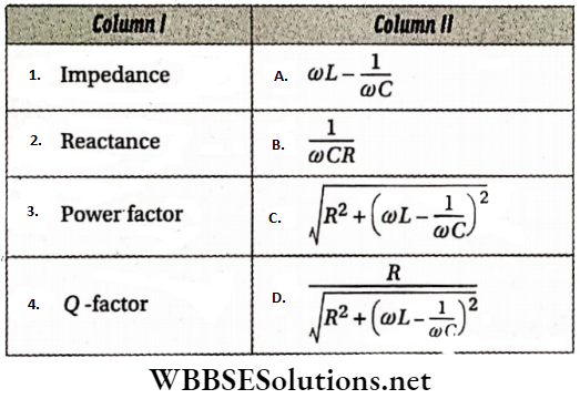
Answer: 1-C, 2-A, 3-D, 4-B
Question 2. An LCR circuit (R = 40 Ω, L = 100mH, C = 0.242 μF) is connected with an ac voltage source of peak voltage 200 V and frequency 1000 Hz.
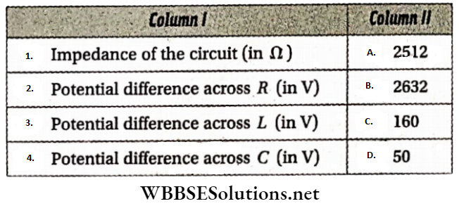
Answer: 1-D, 2-C, 3-A, 4-B
Question 3. Column I describes some action and column 2 the required device.
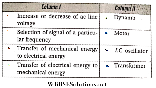
Answer: 1-D, 2-C, 3-A, 4-B
Question 4. In an LR circuit instantaneous voltage and instantaneous current are V = 100 sin100t and i = I0 sin(100t – \(\frac{\pi}{4}\) respectively.
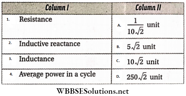
Answer: 1-B, 2-C, 3-A, 4-D
Question 5. Referring to the given circuit, match the following.
image
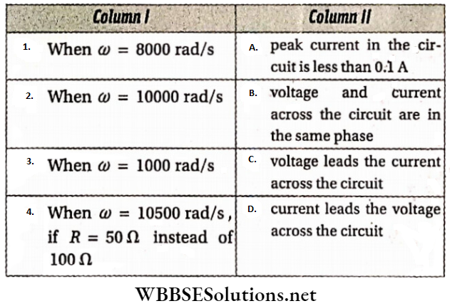
Answer: 1-A and D, 2-B, 3-A and D, 4-C
Alternating Current derivations for Class 12 WBCHSE
Alternating Current Comprehension Type Questions And Answers
Read the following passage carefully and answer the questions at the end of It.
Question 1. A series combination of an inductor of self-inductance L, capacitor of capacitance C, and resistor of resistance R is connected to an alternating voltage source of V=V0 sin ωt. The current through the circuit is I = I0 sin(t-0), where \(I_0=\frac{V_0}{\sqrt{R^2+\left(\omega L-\frac{1}{\omega C}\right)^2}}\) and \(\theta=\tan ^{-1} \frac{1}{R}\left(\omega L-\frac{1}{\omega C}\right)\).
Note that, the frequency of both voltage and, current is \(f=\frac{\omega}{2 \pi}\). The rms value of these parameters during one complete cycle are \(V_{\mathrm{rms}}=\frac{V_0}{\sqrt{2}} \text { and } I_{\mathrm{rms}}=\frac{I_0}{\sqrt{2}}\) respectively. These values are shown in alternating voltmeter and ammeter.
The power consumed by the circuit P = VI. The mean value i.e., the effective power of the circuit in a complete cycle is \(\bar{P}=V_{\mathrm{rms}} I_{\mathrm{rms}} \cos \theta\). This cos θ is termed the power factor.
1. V = V0 sin ωt electromotive force is applied to an alternating circuit consisting of resistance R’ and an inductor of self-inductance L. The phase difference between the voltage and current is
- 90°
- \(\tan ^{-1} \frac{\omega L}{R^{\prime}}\)
- \(\tan ^{-1} \frac{R^{\prime}}{\sqrt{\left(R^{\prime}\right)^2+\omega^2 L^2}}\)
- \(\tan ^{-1} \frac{\sqrt{R^{\prime 2}+\dot{\omega}^2 L^2}}{R^{\prime}}\)
Answer: 2. \(\tan ^{-1} \frac{\omega L}{R^{\prime}}\)
2. The power factor of the circuit in question (1) is
- Zero
- \(\frac{\omega L}{R^{\prime}}\)
- \(\frac{R^{\prime}}{\sqrt{R^{\prime 2}+\omega^2 L^2}}\)
- \(\frac{\sqrt{R^{\prime 2}+\omega^2 L^2}}{R^{\prime}}\)
Answer: 3. \(\frac{R^{\prime}}{\sqrt{R^{\prime 2}+\omega^2 L^2}}\)
3. In the circuit in question (1) the inductor is replaced by a pure capacitor; the phase difference between the current and terminal voltage of the capacitor is
- -90°
- zero
- Between -90° and zero
- +90°
Answer: 1. -90°
4. The power factor of the circuit in question (3) is
- -1
- Zero
- Between zero and 1
- 1
Answer: 3. Between zero and 1
5. The voltage applied in an LCR circuit having R = 10Ω, L = 10 mH and C = 1 μF is V = 20 sin ωt volt. For what frequency of the applied voltage will the current reach Its peak value?
- 159 Hz
- 1592 Hz
- 1.59 x 10⁴ Hz
- 1.59 x 10⁵ Hz
Answer: 2. 1592 Hz
6. The phase difference between the voltage and peak current in question (v) is
- Zero
- -90°
- +90°
- 180°
Answer: 1. Zero
7. Which element is responsible for the power consumption in an alternating current circuit?
- Only resistor
- Only Inductor
- Only capacitor
- Resistor, inductor, and capacitor
Answer: 2. Only Inductor
8. The frequency of the applied alternating voltage In an. ac circuit is 50 Hz. The resistance and self-inductance of the circuit are 37.6 fL and 120 mH. The phase difference between the voltage and current is
- Zero
- 45°
- 60°
- 90°
Answer: 2. 45°
Question 2. A transformer is a device used to increase or decrease the voltage in the transmission line according to requirements. Generally, the input line voltage is fed into a primary coil and the output line voltage is obtained from the terminals of another coil. In an ideal transformer, the primary and secondary coils are linked in such a way that there is no loss of magnetic flux and electrical energy.
In an ideal transformer, if the number of turns and input voltage across the terminals of the primary coil are N1 and V1, then the output voltage at the two terminals of the secondary coil \(V_2=V_1 \cdot \frac{N_2}{N_1}\), where N2 is. the number of turns in the secondary coil.
1. The ratio of the number of turns of the primary and secondary coils of an ideal transformer is 2: 1. If the input voltage is 440 V, then the output voltage is
- 220 V
- 440 V
- 88 W
- None of these
Answer: 1. 220 V
2. In question (1) if the input power of the transformer is 44 W, then the output power is
- 22 W
- 44 W
- 88 W
- None of these
Answer: 2. 44 W
3. In the above-mentioned transformer the input and output currents are respectively,
- 100 mA, 100 mA
- 200 mA, 200 mA
- 100 mA, 200 mA
- 200 mA, 100 mA
Answer: 3. 100 mA, 100 mA
Alternating Current Integer Answer Type Questions And Answers
In this type, the answer to each of the questions is a single-digit integer ranging from 0 to 9.
Question 1. A resistance and a capacitor are connected in series with an alternating voltage of rms value 13 V. The terminal voltage of the resistor is 12 V and that across the capacitor is (n + 0.38) V. What is the value of n?
Answer: 6
Question 2. The current and voltage in an ac circuit are \(I=\sin \left(100 t+\frac{\pi}{3}\right) \mathrm{A}\) and V = 20 sin 100 tV. Calculate the power of the circuit in W.
Answer: 5
Question 3. In a series LCR circuit, the capacitance C is replaced by 2C. To keep the resonance frequency unchanged, the inductance has to be replaced by an inductance of L’. Find the ratio of L and L’.
Answer: 2
Question 4. An alternating voltage of 5 V of frequency 50 Hz is connected to a series LCR circuit. The potential difference across the inductor and resistor is 6 V and 4 V respectively. What is the voltage across the capacitor (in V)?
Answer: 3
Question 5. In a series LCR circuit R = 1 kΩ, C = 2μF, and the potential difference across R is 2 V. At resonance ω = 200 rad.s-1. What is the potential difference (in V) across L at resonance? across
Answer: 5
Question 6. In a series LCR circuit R = 25Ω, L = 10 mH, and C = 1μF. The circuit is connected to an AC source of variable frequency. What is the Q-factor of the circuit?
Answer: 4
Question 7. A current of 50 mA flows through a 4 μF capacitor connected to a 500 Hz ac source. The terminal potential difference (in V) across the capacitor is (η + 0.98). What is the value of η? (π = 3.14)
Answer: 3
Question 8. In the figure, an LCR series circuit is shown. What would be the ammeter reading ampere?
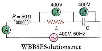
Answer: 8